EP0170823A1 - Printer with device for use in the removal of a printed portion from a continuous web document - Google Patents
Printer with device for use in the removal of a printed portion from a continuous web document Download PDFInfo
- Publication number
- EP0170823A1 EP0170823A1 EP85107129A EP85107129A EP0170823A1 EP 0170823 A1 EP0170823 A1 EP 0170823A1 EP 85107129 A EP85107129 A EP 85107129A EP 85107129 A EP85107129 A EP 85107129A EP 0170823 A1 EP0170823 A1 EP 0170823A1
- Authority
- EP
- European Patent Office
- Prior art keywords
- web
- housing
- document
- access cover
- operating mechanism
- Prior art date
- Legal status (The legal status is an assumption and is not a legal conclusion. Google has not performed a legal analysis and makes no representation as to the accuracy of the status listed.)
- Granted
Links
Images

Classifications
-
- B—PERFORMING OPERATIONS; TRANSPORTING
- B41—PRINTING; LINING MACHINES; TYPEWRITERS; STAMPS
- B41J—TYPEWRITERS; SELECTIVE PRINTING MECHANISMS, i.e. MECHANISMS PRINTING OTHERWISE THAN FROM A FORME; CORRECTION OF TYPOGRAPHICAL ERRORS
- B41J11/00—Devices or arrangements of selective printing mechanisms, e.g. ink-jet printers or thermal printers, for supporting or handling copy material in sheet or web form
- B41J11/66—Applications of cutting devices
- B41J11/70—Applications of cutting devices cutting perpendicular to the direction of paper feed
-
- Y—GENERAL TAGGING OF NEW TECHNOLOGICAL DEVELOPMENTS; GENERAL TAGGING OF CROSS-SECTIONAL TECHNOLOGIES SPANNING OVER SEVERAL SECTIONS OF THE IPC; TECHNICAL SUBJECTS COVERED BY FORMER USPC CROSS-REFERENCE ART COLLECTIONS [XRACs] AND DIGESTS
- Y10—TECHNICAL SUBJECTS COVERED BY FORMER USPC
- Y10T—TECHNICAL SUBJECTS COVERED BY FORMER US CLASSIFICATION
- Y10T225/00—Severing by tearing or breaking
- Y10T225/20—Severing by manually forcing against fixed edge
- Y10T225/238—With housing for work supply
-
- Y—GENERAL TAGGING OF NEW TECHNOLOGICAL DEVELOPMENTS; GENERAL TAGGING OF CROSS-SECTIONAL TECHNOLOGIES SPANNING OVER SEVERAL SECTIONS OF THE IPC; TECHNICAL SUBJECTS COVERED BY FORMER USPC CROSS-REFERENCE ART COLLECTIONS [XRACs] AND DIGESTS
- Y10—TECHNICAL SUBJECTS COVERED BY FORMER USPC
- Y10T—TECHNICAL SUBJECTS COVERED BY FORMER US CLASSIFICATION
- Y10T225/00—Severing by tearing or breaking
- Y10T225/20—Severing by manually forcing against fixed edge
- Y10T225/287—With brake or clamp
- Y10T225/293—Manually applied, spring returned
-
- Y—GENERAL TAGGING OF NEW TECHNOLOGICAL DEVELOPMENTS; GENERAL TAGGING OF CROSS-SECTIONAL TECHNOLOGIES SPANNING OVER SEVERAL SECTIONS OF THE IPC; TECHNICAL SUBJECTS COVERED BY FORMER USPC CROSS-REFERENCE ART COLLECTIONS [XRACs] AND DIGESTS
- Y10—TECHNICAL SUBJECTS COVERED BY FORMER USPC
- Y10T—TECHNICAL SUBJECTS COVERED BY FORMER US CLASSIFICATION
- Y10T225/00—Severing by tearing or breaking
- Y10T225/20—Severing by manually forcing against fixed edge
- Y10T225/295—Blade manually movable to or from severing position
Definitions
- the present invention relates generally to apparatus for performing operations on a continuous web material and in particular to a device for use in the removal of a portion of the material after an operation has been performed on it.
- the invention has a particular application in a printer which performs printing operations on a continuous web document and enables a printed individual form or page to be torn away from the rest of the document along a transversely extending perforated tear line spaced closely downstream of the printing station of the printer.
- Computer output printers are usually provided with document feeding pin or spur wheels for engagement with uniformly spaced pin feed holes along opposite edges of a continuous web document.
- a continuous web document may be formed with transversely extending perforated tear lines spaced along the length of the document to permit tearing of the document into individual pages.
- the document is fed between a print head and a platen forming a printing station which is located within the housing of the printer and spaced some distance from the exit opening in the printer housing through which the continuous web document passes after the printing operation has been performed on the document.
- An individual page of the continuous web document after having a printing operation performed on it, can be removed by waiting until the printed page has moved to a position outside the housing, usually after one or more additional pages have been printed.
- This individual printed page removal arrangement is satisfactory if the printer is operated in a substantially continuous manner. However, this individual printed page removal arrangement is not satisfactory if the printer is operated only periodically and the printed page is needed as soon as printing is completed.
- the printer may be provided with a reverse feeding arrangement so that, after the tear line has been advanced to a position outside the printer housing to permit removal of a printed sheet, the document can then be fed in a reverse direction and back into the printer. This reverse feeding can be continued until the tear line is positioned in the proper position just downstream of the printing station so that a page is not wasted.
- a reverse feeding arrangement adds to the cost and complexity of manufacture of the printer.
- the object of the present invention is to provide an improved device for use in the removal of a portion of a continuous web of material after an operation, for example a printing operation, has been performed on it which does not require the incorporation of a reverse feeding arrangement for the continuous web material and which permits the removal of the required portion of the continuous web material without wasting an appreciable amount of the rest of the material.
- the present invention relates to apparatus for performing operations on a continuous web of material including a housing, an operating mechanism located within the housing for performing operations on the web of material, a web feeding mechanism located within the housing for feeding the web past the operating mechanism so that the operating mechanism can perform operations on the web, and a device for use in the removal of a portion of the web on which operations have been performed.
- the device for use in the removal of a portion of the web comprises a web engaging member movably supported within the housing for movement between a normal position in which it is spaced from the web to allow free passage of the web past the operating mechanism and an operating position in which it engages and grips a portion of the web downstream of the operating mechanism.
- the device further comprises an operating member connected to the web engaging member and located outside the housing for operation by an operator to move the web engaging member from the normal free passage position into the operating web engaging position, whereby the web may be engaged and gripped by the web engaging member while the portion of the web located downstream of the web engaging member may be torn off from the rest of the web.
- the portion of the web on which an operation has been performed can be torn off from the rest of the web at a position close to the operating mechanism. As a result only the small portion of the web between the operating mechanism and the web engaging member of the device is wasted.
- the invention has a particular application in a printer in which the web is a continuous web document and the operating mechanism is a printing mechanism.
- the device for use in the removal of a portion of a continuous web of material in accordance with the present invention is illustrated as being incorporated in the access cover of a computer output printer including a document transport system of the type disclosed in European Patent Application 85105545.9 filed on 7 May 1985. Only so much of the document transport system of the above application is described herein as is necessary for an understanding of the present invention. Reference may be made to the above copending application for any details of the document transport system not described herein.
- the printer includes an outer housing 10 surrounding a printer frame assembly having snap-together moulded plastic parts that may be readily assembled with robotic techniques.
- the details of the frame assembly are disclosed in European Patent Application 85105550.9 filed on 7 May 1985.
- the printer includes a printing station having printer means, illustrated as a wire matrix print head 13 cooperating with a platen 14, for printing characters on a document.
- the platen 14 extends across the width of the printer and the ends of the platen are supported in end frames of the printer with the front face of the platen 14 being located in a plane at right angles to the print wires of the print head 13.
- a document being printed moves across the front face of the platen 14, between the platen 14 and the print head 13, during its travel through the printing station.
- the print head 13 is supported for transverse movement back and forth across the printer on a guide bracket 16 supported at its front and rear ends on guide rods 17, 18 respectively.
- the guide bracket 16 is moved back and forth across the printer along the guide rods 17, 18 by a worm-type screw 20 which is driven by a suitable stepping motor, not shown.
- An ink ribbon cartridge 22 is removably supported above the guide bracket 16 for feeding an ink ribbon between the print head 13 and the document so that, during operation of the print head 13, the print wires in the print head engage the ribbon and cause the printing of marks on the document.
- the printer is provided with a document feeding system including a friction roll document feeding means and a pin wheel document feeding means.
- the friction roll document feeding means is positioned immediately below or in advance of the printing station for feeding a document upwardly between the print head 13 and the platen 14.
- the friction roll document feeding means includes a first set of friction roll wheels 24 of a relatively small diameter supported on and driven by a drive shaft 25.
- the friction roll wheels 24 are spaced apart across the width of the printer and are located immediately below the path of the back and forth movement of the print head 13 so that the surfaces of the friction roll wheels 24 engage one face of the document immediately below the print head 13.
- a second set of friction roll wheels 26 are spaced apart across the width of the printer and engage in pairs with the friction roll wheels 24 to form a nip.
- the document in the printer passes through the nip so that the surfaces of the friction roll wheels 26 engage the opposite face of the document.
- the friction roll wheels 26 are larger in diameter than the friction roll wheels 24 and are supported on and driven by a drive shaft 27 which is drivingly connected by suitable gears, not shown, to the drive shaft 25 so that the friction roll wheels 24, 26 rotate in opposite directions at the same peripheral speed.
- the pin wheel document feeding means is positioned in advance of or upstream of the friction roll document feeding means for feeding a document of the continuous web type, as indicated at D in Figure 2.
- This continuous web document D has uniformly spaced pin feed holes 30 along its outer edge portions, longitudinally extending perforated tear lines 29 adjacent the pin feed holes 30, and transversely extending perforated tear lines 31 in spaced-apart relationship along the length of the continuous web document D.
- the pin wheel document feeding means includes a pair of pin wheels 33 formed with uniformly spaced outwardly projecting pins 34 on their outer surfaces.
- the pin wheels 33 are supported on a square drive shaft 35 ( Figure 1) by corresponding support assemblies, broadly indicated at 36.
- These support assemblies 36 can be moved along the shaft 35 to provide for adjustment of the positions of the pin wheels 33 transversely relative to the document being fed.
- Each support assembly 36 is maintained in an adjusted position on the drive shaft 35 and a guide support shaft 38.
- the drive shaft 35 for the pin wheels 33 is drivingly connected through suitable gearing, not shown, to the drive shafts 25, 27 supporting the friction drive roll wheels 24, 26.
- the continuous web document D is guided into the printer from a fan-folded stack or from a continuous roll supply (not illustrated) and along the upper surface of the rear portion of the housing 10.
- the continuous web document D passes downwardly around a curved path of travel over a pair of curved guide plates 40 which are formed integrally with the two support assemblies 36 and extend downwardly in closely spaced relationship with the rear peripheral surfaces of the pin wheels 33.
- the medial portions of the guide plates 40 closely follow the contour of the rear peripheral surfaces of the pin wheels 33 and are slotted to permit passage of the pins 34 therethrough so that the pin feed holes 30 are engaged by the pins 34.
- the lower portions of the guide plates 40 extend downwardly at an angle from the pin wheels 33 and guide the document D towards the lower peripheral surfaces of the large friction roll wheels 26 ( Figures 3 and 4).
- a guide plate 42 is supported on the drive shaft 27 and is formed with fingers which extend respectively into the spaces between adjacent friction roll wheels 26.
- the guide plate 42 is curved upward at its lower portion at substantially the same radius as the outer peripheral surfaces of the friction roll wheels 26 to aid in guiding the document D underneath the wheels 26 after the document D has been guided downwardly by the lower portions of the guide plates 40.
- a moulded lower guide plate 44 extends transversely from one side to the other of the printer and is supported on the base 12 so that it extends beneath the pin wheels 33, the friction roll wheels 24, 26 and the printing station.
- the upper rear portion of the guide plate 44 is positioned to the rear of and spaced from the guide plates 40 and pin wheels 33.
- the medial portion of the guide plate 44 includes an upwardly curved portion which is spaced from and follows the curved configuration of the lower peripheral surfaces of the friction roll wheels 26 and acts to guide the continuous web document D around the friction roll wheels 26 and into the nip between the friction roll wheels 24, 26.
- the front portion of the lower guide plate 44 curves downwardly and extends along the base 12 to the front of the printer.
- An upper front guide plate 46 extends transversely across the printer and includes a downwardly curved front portion spaced above the front portion of the lower guide plate 44 to form a relatively wide opening or "mouth" on the front panel of the housing 10.
- the rear portion of the upper front guide plate 46 curves upwardly closely adjacent to the upwardly curving portion of the lower guide plate 44 and has a rear edge which supports an upwardly extending plastic sheet guide 47 having finger portions extending upwardly through the spaces between adjacent pairs of friction roll wheels 24, 26 beyond the nip formed by the friction roll wheels 24, 26.
- the continuous web document D is thus guided into the printer by the pin wheels 33 and fed to the printing station by the friction rolls wheels 24, 26 and then normally directed outwardly through an exit opening in an access cover on the upper surface of the housing 10.
- a printing line is formed by the print head 13 on the portion of the document D in the printing station a considerable distance below the upper surface of the housing 10.
- This arrangement of document portion removal is satisfactory if the printer is operated in a substantially continuous manner. However, this arrangement is not satisfactory if the printer is operated only periodically and the printed portions are needed as soon as printing is completed.
- the tearing force necessary to separate the last printed portion may cause the rest of the continuous web document D to be pulled out of its normal longitudinal path of travel between the friction roll wheels 24, 26. Also, the tearing force may be great enough to tear the pin feed holes 30 and/or the perforated tear lines 29 so that the document D is damaged and wasted.
- the pin wheels 33 provide the only positive gripping force applied to the continuous web document D and this positive gripping force is applied a considerable distance upstream of the platen 14.
- the device for use in tearing off a printed portion of the document D in accordance with the present invention includes a document engaging member which is movably supported adjacent to the platen 14 for movement into an operating position in which it engages and grips the document at a plurality of points along a line immediately downstream of the printing station and adjacent to the tear line associated with the printed portion to be torn off.
- An operating member accessible from outside the housing is used to move the document engaging member into its operating position. When the engaging member is in this operating position it engages the document and prevents movement of the portion of the document in the printing station and permits tearing of the printed portion along the associated tear line while ensuring that the tear line is positioned within the housing and closely adjacent to the printing station.
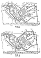
- the document engaging member is illustrated as comprising a clamping edge on the lower portion of a gripper bar 50 which extends transversely of the platen 14 and is movable between a normal position in which it is spaced from the document D, as illustrated in Figure 3, to allow free passage of the document over the platen 14, and an operating position in which it engages the document along a line immediately downstream of the printing station and presses the document against the platen 14, as illustrated in Figure 4.
- the clamping edge of the gripper bar 50 is illustrated as being relatively sharp. However, this clamping edge should not be sharp enough to cut the document D or to cause the document to be torn along the clamping edge instead of along the tear line.
- the gripper bar 50 is supported by an operating member accessible from outside the housing 10 for displacement by an operator to move the gripper bar 50 from the normal free passage position of Figure 3 to the operating document engaging position of Figure 4.
- the operating member is illustrated as comprising an access cover, broadly indicated at 52, moulded from a suitable thermoplastic material and supported for sliding backwards and forwards movement on the upper surface of the housing 10. Opposite side edge portions of the cover 52 are supported for horizontal backwards and forwards sliding movement above the access opening in the housing 10 by integrally moulded slide bars 53.
- the front edge of the cover 52 is provided with a forwardly extending retaining lip 54 which is adapted to extend beneath a corresponding rearwardly extending lip on the upper surface of the housing 10, as illustrated in Figures 3 and 4.
- Resilient means is associated with the housing 10 and the access cover 52 for normally maintaining the access cover 52 and the gripper bar 50 in the front free passage position shown in Figure 3.
- This resilient means includes integrally moulded downwardly extending detents 55 on the opposite side portions of the rear portion of the cover 52.
- the detents 55 have notched rear lower surfaces. As shown in Figures 3 and 4, the notched rear lower surface of each of the detents 55 is adapted to be resiliently engaged by a cammed detent 56 on the upper end of the front leg of a moulded U-shaped spring member 58, the rear leg of which is integrally moulded with the front edge of the access opening of the housing 10.
- the U-shaped spring members 58 normally urge the access cover 52 in a forward direction and each cammed detent 56 is engaged with the notch in the associated detent 55 to maintain the rear portion of the cover 52 in a latched and closed position and in sliding engagement with the slide bars 53.
- the lip 54 along the front edge of the cover 52 slides backwards and forwards under the corresponding lip of the upper surface of the housing 10 and retains the front portion of the cover 52 in a closed position.
- the access cover 52 may be removed by simply lifting the rear portion of the cover 52 so that each cammed detent 56 snaps out of the locking notch in the associated detent 55.
- the lip 54 is inserted under the corresponding lip of the upper surface of the housing 10 and the rear portion of the cover 52 is moved down into position on the slide bars 53 so that each cammed detent 56 snaps into a latched position with the locking notch on the associated detent 55, as illustrated in Figures 3 and 4.
- the front portion of the access cover 52 is provided with an integrally moulded upstanding enclosure 60 which extends over and covers the ribbon cartridge 22 and also serves as a handle for use in manually moving the access cover 52 to a rear position, as illustrated in Figure 2.
- the rear portion of the upstanding enclosure 60 slants downwardly and extends inside the upper portion of the housing 10 to provide a support portion in the form of a sloping wall 62 extending downwardly and rearwardly at an angle of 40 degrees.
- the sloping wall 62 enables the portion of the document in the area of the platen 14 and adjacent the printing station to be seen from outside the printer housing.
- the upper edge portion of the gripper bar 50 is integrally moulded with the lower edge portion of the sloping wall 62 and includes integrally formed hinged members for supporting the front portion of a hinged cover 64.
- the hinged cover 64 is supported for movement between a closed rear document guiding and sound or noise blocking position, as shown in Figure 3, and an open front free access position in which it permits the tearing of an individual printed portion from the rest of the continuous web document D, as shown in Figure 4.
- the entire access cover 52 may be formed from a clear transparent moulded plastic material, if desired. However, it is preferred that the access cover 52 be formed from a plastic material which is translucent and may be provided with a satin or roughened finish to prevent glare while partially obscuring the printer mechanism housed therebeneath.
- the hinged cover 64 may also be formed from the same type of translucent plastic material. However, at least the portion of the hinged cover 64 adjacent the hinged connection with the access cover 52 is preferably transparent to provide a clear view of the portion of the continuous web document D adjacent to the printing station.
- each printed portion of the continuous web document D will be fed forwardly automatically and the next successive tear line 31 will eventually become positioned in alignment with the upper edge of the platen 14, as illustrated in Figure 4.
- the document D can be pressed against the platen 14 by the clamping edge on the gripper bar 50 immediately upstream of the tear line 31 and thereby gripped.
- the feed switch 48 may be depressed to feed the document D forwardly, or the manual knob 49 can be rotated to feed the document D forwardly, until the tear line 31 upstream of the portion which has just been printed is positioned in alignment with the upper edge of the platen 14, as illustrated in Figure 4.
- the hinged cover 64 is moved to the front open position shown in Figure 4.
- the front edge of the upstanding enclosure 60 is then pushed rearwardly by the operator, as illustrated in Figure 2, so that the clamping edge of the gripper bar 50 forces the document into gripping engagement with the platen 14.
- the gripper bar 50 maintains the document in this fixed position while the printed portion of the document D is torn from the rest of the document by the operator, as illustrated in Figure 2.
- the front edge of the upstanding enclosure 60 of the access cover 52 is released and the U-shaped spring members 58 urge the access cover 52 back into its front position, as shown in Figure 3, so that the document is released by the clamping edge of the gripper bar 50 to allow free passage of the document between the print head 13 and the platen 14.
- the hinged cover 64 is then swung to the rear position where it serves as a paper guide and as a noise reducing closure for the opening in the access cover 52.
- the next portion of the document D is then fed into the printing station where line-by-line printing is performed. As printing proceeds, the leading edge of the document D is guided outwardly through the exit opening at the rear of the hinged cover 64 and printing of successive portions of the document D continues until it is once again desired to remove a portion of the document which has just been printed.
Abstract
Description
- The present invention relates generally to apparatus for performing operations on a continuous web material and in particular to a device for use in the removal of a portion of the material after an operation has been performed on it. The invention has a particular application in a printer which performs printing operations on a continuous web document and enables a printed individual form or page to be torn away from the rest of the document along a transversely extending perforated tear line spaced closely downstream of the printing station of the printer.
- Computer output printers are usually provided with document feeding pin or spur wheels for engagement with uniformly spaced pin feed holes along opposite edges of a continuous web document. Such a document may be formed with transversely extending perforated tear lines spaced along the length of the document to permit tearing of the document into individual pages. The document is fed between a print head and a platen forming a printing station which is located within the housing of the printer and spaced some distance from the exit opening in the printer housing through which the continuous web document passes after the printing operation has been performed on the document.
- An individual page of the continuous web document, after having a printing operation performed on it, can be removed by waiting until the printed page has moved to a position outside the housing, usually after one or more additional pages have been printed. This individual printed page removal arrangement is satisfactory if the printer is operated in a substantially continuous manner. However, this individual printed page removal arrangement is not satisfactory if the printer is operated only periodically and the printed page is needed as soon as printing is completed.
- If it is desired to remove from a continuous web document an individual page which has just been printed, it is the usual practice to feed the document until the tear line located upstream of the page to be removed is outside the printer housing. The document can then be manually gripped below (upstream of) the tear line as the page is torn from the rest of the continuous document. This results in wasting an appreciable portion of the rest of the document because the document must be advanced to a position where the relevant tear line is outside the printer housing and a considerable distance downstream of the printing station.
- In some instances, the printer may be provided with a reverse feeding arrangement so that, after the tear line has been advanced to a position outside the printer housing to permit removal of a printed sheet, the document can then be fed in a reverse direction and back into the printer. This reverse feeding can be continued until the tear line is positioned in the proper position just downstream of the printing station so that a page is not wasted. However, the provision of forward and reverse feeding arrangements adds to the cost and complexity of manufacture of the printer.
- The object of the present invention is to provide an improved device for use in the removal of a portion of a continuous web of material after an operation, for example a printing operation, has been performed on it which does not require the incorporation of a reverse feeding arrangement for the continuous web material and which permits the removal of the required portion of the continuous web material without wasting an appreciable amount of the rest of the material.
- The present invention relates to apparatus for performing operations on a continuous web of material including a housing, an operating mechanism located within the housing for performing operations on the web of material, a web feeding mechanism located within the housing for feeding the web past the operating mechanism so that the operating mechanism can perform operations on the web, and a device for use in the removal of a portion of the web on which operations have been performed.
- In accordance with the invention the device for use in the removal of a portion of the web comprises a web engaging member movably supported within the housing for movement between a normal position in which it is spaced from the web to allow free passage of the web past the operating mechanism and an operating position in which it engages and grips a portion of the web downstream of the operating mechanism.
- The device further comprises an operating member connected to the web engaging member and located outside the housing for operation by an operator to move the web engaging member from the normal free passage position into the operating web engaging position, whereby the web may be engaged and gripped by the web engaging member while the portion of the web located downstream of the web engaging member may be torn off from the rest of the web.
- By using a device in accordance with the invention which is located within the housing of the apparatus, the portion of the web on which an operation has been performed can be torn off from the rest of the web at a position close to the operating mechanism. As a result only the small portion of the web between the operating mechanism and the web engaging member of the device is wasted.
- The invention has a particular application in a printer in which the web is a continuous web document and the operating mechanism is a printing mechanism.
- In order that the invention may be more readily understood an embodiment will now be described with reference to the accompanying drawings, in which:
- Figure 1 is an isometric view of a computer output printer including a device for use in the removal of a printed portion of a continuous web document in accordance with the invention,
- Figure 2 is a fragmentary isometric view of the upper portion of the printer illustrated in Figure 1 showing the manner in which the device for use in the removal of a portion of a document is moved to engage and grip the document while the operator is tearing off an individual printed portion from the rest of the document,
- Figure 3 is a side view of the front part of the printer illustrated in Figure 1 on a larger scale and sectioned on the line X - X in Figure 1 with the device for use in the removal of a portion of a document shown in its normal position to allow free passage of the document through the printer, and
- Figure 4 is a side view as in Figure 3 but showing the device for use in the removal of a portion of a document in its operating position with the document being gripped along a line immediately downstream of the printing station of the printer.
- The device for use in the removal of a portion of a continuous web of material in accordance with the present invention is illustrated as being incorporated in the access cover of a computer output printer including a document transport system of the type disclosed in European Patent Application 85105545.9 filed on 7 May 1985. Only so much of the document transport system of the above application is described herein as is necessary for an understanding of the present invention. Reference may be made to the above copending application for any details of the document transport system not described herein.
- The printer includes an
outer housing 10 surrounding a printer frame assembly having snap-together moulded plastic parts that may be readily assembled with robotic techniques. The details of the frame assembly are disclosed in European Patent Application 85105550.9 filed on 7 May 1985. The printer includes a printing station having printer means, illustrated as a wirematrix print head 13 cooperating with aplaten 14, for printing characters on a document. Theplaten 14 extends across the width of the printer and the ends of the platen are supported in end frames of the printer with the front face of theplaten 14 being located in a plane at right angles to the print wires of theprint head 13. A document being printed moves across the front face of theplaten 14, between theplaten 14 and theprint head 13, during its travel through the printing station. - The
print head 13 is supported for transverse movement back and forth across the printer on aguide bracket 16 supported at its front and rear ends onguide rods guide bracket 16 is moved back and forth across the printer along theguide rods type screw 20 which is driven by a suitable stepping motor, not shown. Anink ribbon cartridge 22 is removably supported above theguide bracket 16 for feeding an ink ribbon between theprint head 13 and the document so that, during operation of theprint head 13, the print wires in the print head engage the ribbon and cause the printing of marks on the document. - The printer is provided with a document feeding system including a friction roll document feeding means and a pin wheel document feeding means. The friction roll document feeding means is positioned immediately below or in advance of the printing station for feeding a document upwardly between the
print head 13 and theplaten 14. The friction roll document feeding means includes a first set offriction roll wheels 24 of a relatively small diameter supported on and driven by adrive shaft 25. Thefriction roll wheels 24 are spaced apart across the width of the printer and are located immediately below the path of the back and forth movement of theprint head 13 so that the surfaces of thefriction roll wheels 24 engage one face of the document immediately below theprint head 13. A second set offriction roll wheels 26 are spaced apart across the width of the printer and engage in pairs with thefriction roll wheels 24 to form a nip. The document in the printer passes through the nip so that the surfaces of thefriction roll wheels 26 engage the opposite face of the document. Thefriction roll wheels 26 are larger in diameter than thefriction roll wheels 24 and are supported on and driven by adrive shaft 27 which is drivingly connected by suitable gears, not shown, to thedrive shaft 25 so that thefriction roll wheels - The pin wheel document feeding means is positioned in advance of or upstream of the friction roll document feeding means for feeding a document of the continuous web type, as indicated at D in Figure 2. This continuous web document D has uniformly spaced
pin feed holes 30 along its outer edge portions, longitudinally extendingperforated tear lines 29 adjacent thepin feed holes 30, and transversely extendingperforated tear lines 31 in spaced-apart relationship along the length of the continuous web document D. The pin wheel document feeding means includes a pair ofpin wheels 33 formed with uniformly spaced outwardly projectingpins 34 on their outer surfaces. Thepin wheels 33 are supported on a square drive shaft 35 (Figure 1) by corresponding support assemblies, broadly indicated at 36. Thesesupport assemblies 36 can be moved along theshaft 35 to provide for adjustment of the positions of thepin wheels 33 transversely relative to the document being fed. Eachsupport assembly 36 is maintained in an adjusted position on thedrive shaft 35 and aguide support shaft 38. Thedrive shaft 35 for thepin wheels 33 is drivingly connected through suitable gearing, not shown, to thedrive shafts drive roll wheels - The continuous web document D is guided into the printer from a fan-folded stack or from a continuous roll supply (not illustrated) and along the upper surface of the rear portion of the
housing 10. The continuous web document D passes downwardly around a curved path of travel over a pair ofcurved guide plates 40 which are formed integrally with the twosupport assemblies 36 and extend downwardly in closely spaced relationship with the rear peripheral surfaces of thepin wheels 33. The medial portions of theguide plates 40 closely follow the contour of the rear peripheral surfaces of thepin wheels 33 and are slotted to permit passage of thepins 34 therethrough so that thepin feed holes 30 are engaged by thepins 34. - The lower portions of the
guide plates 40 extend downwardly at an angle from thepin wheels 33 and guide the document D towards the lower peripheral surfaces of the large friction roll wheels 26 (Figures 3 and 4). Aguide plate 42 is supported on thedrive shaft 27 and is formed with fingers which extend respectively into the spaces between adjacentfriction roll wheels 26. Theguide plate 42 is curved upward at its lower portion at substantially the same radius as the outer peripheral surfaces of thefriction roll wheels 26 to aid in guiding the document D underneath thewheels 26 after the document D has been guided downwardly by the lower portions of theguide plates 40. - A moulded
lower guide plate 44 extends transversely from one side to the other of the printer and is supported on thebase 12 so that it extends beneath thepin wheels 33, thefriction roll wheels guide plate 44 is positioned to the rear of and spaced from theguide plates 40 andpin wheels 33. The medial portion of theguide plate 44 includes an upwardly curved portion which is spaced from and follows the curved configuration of the lower peripheral surfaces of thefriction roll wheels 26 and acts to guide the continuous web document D around thefriction roll wheels 26 and into the nip between thefriction roll wheels lower guide plate 44 curves downwardly and extends along thebase 12 to the front of the printer. - An upper
front guide plate 46 extends transversely across the printer and includes a downwardly curved front portion spaced above the front portion of thelower guide plate 44 to form a relatively wide opening or "mouth" on the front panel of thehousing 10. The rear portion of the upperfront guide plate 46 curves upwardly closely adjacent to the upwardly curving portion of thelower guide plate 44 and has a rear edge which supports an upwardly extendingplastic sheet guide 47 having finger portions extending upwardly through the spaces between adjacent pairs offriction roll wheels friction roll wheels - The continuous web document D is thus guided into the printer by the
pin wheels 33 and fed to the printing station by thefriction rolls wheels housing 10. As will be noted in Figures 3 and 4, a printing line is formed by theprint head 13 on the portion of the document D in the printing station a considerable distance below the upper surface of thehousing 10. In order to remove or tear off an individual printed page or portion of the continuous web document D, it is the usual custom to wait until the printed portion has moved to a position outside the housing, usually after one or more additional portions have been printed. This arrangement of document portion removal is satisfactory if the printer is operated in a substantially continuous manner. However, this arrangement is not satisfactory if the printer is operated only periodically and the printed portions are needed as soon as printing is completed. - If it is desired to remove an individual portion which has just been printed, it is the usual practice to feed the document forwardly, for example by depressing a
feed switch button 48, until thetear line 31 upstream of the printed portion is outside the printer housing so that the document can be manually gripped below (upstream of) the tear line as the printed portion is torn from the rest of the continuous document along the tear line. This results in wasting the portion of the document D between the tear line and the printing station. The wasting of this portion of the document D can be avoided by manually feeding the document in the reverse direction by means of amanual knob 49 fixed on the outwardly extending end of the pinwheel drive shaft 35 after the printed portion has been removed. However, this manual reverse feeding wastes the time of the operator. - If the operator attempts to tear and remove the last printed portion as soon as the associated
tear line 31 has passed the printing station and is positioned immediately above theplaten 14, without advancing the document D until thetear line 31 is outside thehousing 10, the tearing force necessary to separate the last printed portion may cause the rest of the continuous web document D to be pulled out of its normal longitudinal path of travel between thefriction roll wheels perforated tear lines 29 so that the document D is damaged and wasted. In the conventional printer thepin wheels 33 provide the only positive gripping force applied to the continuous web document D and this positive gripping force is applied a considerable distance upstream of theplaten 14. - The device for use in tearing off a printed portion of the document D in accordance with the present invention includes a document engaging member which is movably supported adjacent to the
platen 14 for movement into an operating position in which it engages and grips the document at a plurality of points along a line immediately downstream of the printing station and adjacent to the tear line associated with the printed portion to be torn off. An operating member accessible from outside the housing is used to move the document engaging member into its operating position. When the engaging member is in this operating position it engages the document and prevents movement of the portion of the document in the printing station and permits tearing of the printed portion along the associated tear line while ensuring that the tear line is positioned within the housing and closely adjacent to the printing station. - The document engaging member is illustrated as comprising a clamping edge on the lower portion of a
gripper bar 50 which extends transversely of theplaten 14 and is movable between a normal position in which it is spaced from the document D, as illustrated in Figure 3, to allow free passage of the document over theplaten 14, and an operating position in which it engages the document along a line immediately downstream of the printing station and presses the document against theplaten 14, as illustrated in Figure 4. The clamping edge of thegripper bar 50 is illustrated as being relatively sharp. However, this clamping edge should not be sharp enough to cut the document D or to cause the document to be torn along the clamping edge instead of along the tear line. Thegripper bar 50 is supported by an operating member accessible from outside thehousing 10 for displacement by an operator to move thegripper bar 50 from the normal free passage position of Figure 3 to the operating document engaging position of Figure 4. - The operating member is illustrated as comprising an access cover, broadly indicated at 52, moulded from a suitable thermoplastic material and supported for sliding backwards and forwards movement on the upper surface of the
housing 10. Opposite side edge portions of thecover 52 are supported for horizontal backwards and forwards sliding movement above the access opening in thehousing 10 by integrally moulded slide bars 53. The front edge of thecover 52 is provided with a forwardly extending retaininglip 54 which is adapted to extend beneath a corresponding rearwardly extending lip on the upper surface of thehousing 10, as illustrated in Figures 3 and 4. - Resilient means is associated with the
housing 10 and theaccess cover 52 for normally maintaining theaccess cover 52 and thegripper bar 50 in the front free passage position shown in Figure 3. This resilient means includes integrally moulded downwardly extendingdetents 55 on the opposite side portions of the rear portion of thecover 52. Thedetents 55 have notched rear lower surfaces. As shown in Figures 3 and 4, the notched rear lower surface of each of thedetents 55 is adapted to be resiliently engaged by acammed detent 56 on the upper end of the front leg of a mouldedU-shaped spring member 58, the rear leg of which is integrally moulded with the front edge of the access opening of thehousing 10. TheU-shaped spring members 58 normally urge theaccess cover 52 in a forward direction and eachcammed detent 56 is engaged with the notch in the associateddetent 55 to maintain the rear portion of thecover 52 in a latched and closed position and in sliding engagement with the slide bars 53. Thelip 54 along the front edge of thecover 52 slides backwards and forwards under the corresponding lip of the upper surface of thehousing 10 and retains the front portion of thecover 52 in a closed position. - The access cover 52 may be removed by simply lifting the rear portion of the
cover 52 so that eachcammed detent 56 snaps out of the locking notch in the associateddetent 55. To replace thecover 52, thelip 54 is inserted under the corresponding lip of the upper surface of thehousing 10 and the rear portion of thecover 52 is moved down into position on the slide bars 53 so that eachcammed detent 56 snaps into a latched position with the locking notch on the associateddetent 55, as illustrated in Figures 3 and 4. - The front portion of the
access cover 52 is provided with an integrally mouldedupstanding enclosure 60 which extends over and covers theribbon cartridge 22 and also serves as a handle for use in manually moving theaccess cover 52 to a rear position, as illustrated in Figure 2. The rear portion of theupstanding enclosure 60 slants downwardly and extends inside the upper portion of thehousing 10 to provide a support portion in the form of a slopingwall 62 extending downwardly and rearwardly at an angle of 40 degrees. The slopingwall 62 enables the portion of the document in the area of theplaten 14 and adjacent the printing station to be seen from outside the printer housing. The upper edge portion of thegripper bar 50 is integrally moulded with the lower edge portion of the slopingwall 62 and includes integrally formed hinged members for supporting the front portion of a hingedcover 64. The hingedcover 64 is supported for movement between a closed rear document guiding and sound or noise blocking position, as shown in Figure 3, and an open front free access position in which it permits the tearing of an individual printed portion from the rest of the continuous web document D, as shown in Figure 4. - The
entire access cover 52, including the hingedcover 64, may be formed from a clear transparent moulded plastic material, if desired. However, it is preferred that theaccess cover 52 be formed from a plastic material which is translucent and may be provided with a satin or roughened finish to prevent glare while partially obscuring the printer mechanism housed therebeneath. The hingedcover 64 may also be formed from the same type of translucent plastic material. However, at least the portion of the hingedcover 64 adjacent the hinged connection with theaccess cover 52 is preferably transparent to provide a clear view of the portion of the continuous web document D adjacent to the printing station. - Normally, the data stream supplied to the printer will cause each printed portion of the continuous web document D to be fed forwardly automatically and the next
successive tear line 31 will eventually become positioned in alignment with the upper edge of theplaten 14, as illustrated in Figure 4. In this position the document D can be pressed against theplaten 14 by the clamping edge on thegripper bar 50 immediately upstream of thetear line 31 and thereby gripped. If the printer is not adapted to feed the printed portion of the document D automatically into a position in which the associatedtear line 31 is in the proper location for the removal of the printed portion by tearing along the tear line, as described above, thefeed switch 48 may be depressed to feed the document D forwardly, or themanual knob 49 can be rotated to feed the document D forwardly, until thetear line 31 upstream of the portion which has just been printed is positioned in alignment with the upper edge of theplaten 14, as illustrated in Figure 4. When thistear line 31 has become positioned in alignment with the upper edge of theplaten 14, the hingedcover 64 is moved to the front open position shown in Figure 4. The front edge of theupstanding enclosure 60 is then pushed rearwardly by the operator, as illustrated in Figure 2, so that the clamping edge of thegripper bar 50 forces the document into gripping engagement with theplaten 14. Thegripper bar 50 maintains the document in this fixed position while the printed portion of the document D is torn from the rest of the document by the operator, as illustrated in Figure 2. - After the printed portion has been torn from the rest of the document, the front edge of the
upstanding enclosure 60 of theaccess cover 52 is released and theU-shaped spring members 58 urge theaccess cover 52 back into its front position, as shown in Figure 3, so that the document is released by the clamping edge of thegripper bar 50 to allow free passage of the document between theprint head 13 and theplaten 14. The hingedcover 64 is then swung to the rear position where it serves as a paper guide and as a noise reducing closure for the opening in theaccess cover 52. The next portion of the document D is then fed into the printing station where line-by-line printing is performed. As printing proceeds, the leading edge of the document D is guided outwardly through the exit opening at the rear of the hingedcover 64 and printing of successive portions of the document D continues until it is once again desired to remove a portion of the document which has just been printed.
Claims (13)
characterised in that said device comprises
whereby said web (D) may be engaged and gripped by said web engaging member (50) while the portion of said web located downstream of said web engaging member may be torn off from the rest of said web.
Applications Claiming Priority (2)
| Application Number | Priority Date | Filing Date | Title |
|---|---|---|---|
| US06/637,185 US4568211A (en) | 1984-08-02 | 1984-08-02 | Printer with slidable tear bar |
| US637185 | 1984-08-02 |
Publications (2)
| Publication Number | Publication Date |
|---|---|
| EP0170823A1 true EP0170823A1 (en) | 1986-02-12 |
| EP0170823B1 EP0170823B1 (en) | 1990-01-10 |
Family
ID=24554919
Family Applications (1)
| Application Number | Title | Priority Date | Filing Date |
|---|---|---|---|
| EP85107129A Expired - Lifetime EP0170823B1 (en) | 1984-08-02 | 1985-06-11 | Printer with device for use in the removal of a printed portion from a continuous web document |
Country Status (7)
| Country | Link |
|---|---|
| US (1) | US4568211A (en) |
| EP (1) | EP0170823B1 (en) |
| JP (2) | JPS6141572A (en) |
| BR (1) | BR8503517A (en) |
| CA (1) | CA1222215A (en) |
| DE (1) | DE3575279D1 (en) |
| ES (1) | ES8608410A1 (en) |
Families Citing this family (11)
| Publication number | Priority date | Publication date | Assignee | Title |
|---|---|---|---|---|
| US4723857A (en) * | 1984-11-20 | 1988-02-09 | Brother Kogyo Kabushiki Kaisha | Printer with a plastic frame structure |
| US4619538A (en) * | 1985-02-04 | 1986-10-28 | Mannesmann Tally Corporation | Adjustable load, friction feed, quick tear bar mechanism |
| US4806036A (en) * | 1985-11-12 | 1989-02-21 | Genicom Corporation | Printer mechanism carried by upper portion of hinged housing |
| JPH0539894Y2 (en) * | 1986-09-22 | 1993-10-08 | ||
| JPH0616766Y2 (en) * | 1987-12-25 | 1994-05-02 | シチズン時計株式会社 | Printer top cover |
| US5006002A (en) * | 1989-04-11 | 1991-04-09 | Clancy Systems International, Inc. | Portable printing apparatus with movable paper feed gate |
| IT1232523B (en) * | 1989-08-21 | 1992-02-19 | Olivetti & Co Spa | GUIDE AND COVER DEVICE FOR PRINTERS |
| US5244295A (en) * | 1991-09-13 | 1993-09-14 | Matsushita Electric Industrial Co., Ltd. | Printing device having a sound insulating wall |
| US5287980A (en) * | 1992-06-17 | 1994-02-22 | Eddy Associates, Inc. | Ticket dispenser assembly including interlocking dispenser units |
| DE19609527C2 (en) * | 1996-03-11 | 1998-03-12 | Siemens Nixdorf Inf Syst | Arrangement for driving a cutting knife for cutting a tape-shaped recording medium which can be printed in a printing device |
| CN103158373B (en) * | 2011-11-03 | 2016-09-14 | 飞利浦金科威(深圳)实业有限公司 | Printer |
Citations (2)
| Publication number | Priority date | Publication date | Assignee | Title |
|---|---|---|---|---|
| EP0061634A1 (en) * | 1981-03-28 | 1982-10-06 | Kienzle Apparate GmbH | Severing device for edge-perforated form webs |
| US4422787A (en) * | 1982-05-10 | 1983-12-27 | Guthrie George L | Tear bar for a printer |
Family Cites Families (16)
| Publication number | Priority date | Publication date | Assignee | Title |
|---|---|---|---|---|
| US2241357A (en) * | 1939-07-17 | 1941-05-06 | Teletype Corp | Paper tear-off device for typing apparatus |
| US2253744A (en) * | 1939-09-25 | 1941-08-26 | Carl A Witt | Tissue dispenser |
| US2360196A (en) * | 1942-12-05 | 1944-10-10 | Imp Typewriter Co Ltd | Platen carriage of typewriting machines |
| US2554003A (en) * | 1947-11-19 | 1951-05-22 | Underwood Corp | Paper feeding and severing means for typewriting and like machines |
| GB699417A (en) * | 1950-12-08 | 1953-11-04 | W H Smith And Son Ltd | Autographic registers or like recording apparatus with improved tear-off device |
| US3085728A (en) * | 1960-08-13 | 1963-04-16 | Victor Company Of Japan | Severing device for recorded magnetic recording sheets in a magnetic recorder/reproducer |
| US3122228A (en) * | 1961-02-16 | 1964-02-25 | Ibm | Paper slot acoustical seal |
| DE2343858C3 (en) * | 1973-08-30 | 1979-05-03 | Nixdorf Computer Ag, 4790 Paderborn | Electromechanical writing mechanism with roller knife |
| US3901372A (en) * | 1974-07-22 | 1975-08-26 | Teletype Corp | Protective cover with viewing window for printers |
| DE2706209C3 (en) * | 1977-02-14 | 1979-08-09 | Siemens Ag, 1000 Berlin Und 8000 Muenchen | Device for noise dampening of printing devices |
| US4149458A (en) * | 1977-10-21 | 1979-04-17 | Addmaster Corporation | Receipt printer for cash registers and the like |
| US4211498A (en) * | 1978-01-20 | 1980-07-08 | Copal Company Limited | Paper cutting and perforated line forming device of printer |
| JPS55142681A (en) * | 1979-04-26 | 1980-11-07 | Canon Inc | Impact type printer |
| DE3009001C2 (en) * | 1980-03-08 | 1988-07-28 | Adlerwerke Vorm. Heinrich Kleyer Ag, 6000 Frankfurt | Cover for the writing area of printers, typewriters or devices of a similar type |
| JPS57100085A (en) * | 1980-12-15 | 1982-06-22 | Tokyo Electric Co Ltd | Printing device |
| JPS5979182A (en) * | 1982-10-28 | 1984-05-08 | 株式会社東芝 | Control rod for reactor |
-
1984
- 1984-08-02 US US06/637,185 patent/US4568211A/en not_active Expired - Fee Related
-
1985
- 1985-04-24 JP JP8664285A patent/JPS6141572A/en active Pending
- 1985-05-16 CA CA000481702A patent/CA1222215A/en not_active Expired
- 1985-06-11 DE DE8585107129T patent/DE3575279D1/en not_active Expired - Fee Related
- 1985-06-11 EP EP85107129A patent/EP0170823B1/en not_active Expired - Lifetime
- 1985-07-24 BR BR8503517A patent/BR8503517A/en not_active IP Right Cessation
- 1985-08-02 ES ES545849A patent/ES8608410A1/en not_active Expired
- 1985-08-02 JP JP60169936A patent/JPS6147584A/en active Pending
Patent Citations (2)
| Publication number | Priority date | Publication date | Assignee | Title |
|---|---|---|---|---|
| EP0061634A1 (en) * | 1981-03-28 | 1982-10-06 | Kienzle Apparate GmbH | Severing device for edge-perforated form webs |
| US4422787A (en) * | 1982-05-10 | 1983-12-27 | Guthrie George L | Tear bar for a printer |
Also Published As
| Publication number | Publication date |
|---|---|
| ES8608410A1 (en) | 1986-06-16 |
| CA1222215A (en) | 1987-05-26 |
| BR8503517A (en) | 1986-04-22 |
| DE3575279D1 (en) | 1990-02-15 |
| JPS6141572A (en) | 1986-02-27 |
| JPS6147584A (en) | 1986-03-08 |
| EP0170823B1 (en) | 1990-01-10 |
| ES545849A0 (en) | 1986-06-16 |
| US4568211A (en) | 1986-02-04 |
Similar Documents
| Publication | Publication Date | Title |
|---|---|---|
| EP0166132B1 (en) | Printer with multi-function document feeding system | |
| US5882128A (en) | Self-adjusting wheel for directly positioning and holding media during a cutting operation in a printer | |
| EP0170823B1 (en) | Printer with device for use in the removal of a printed portion from a continuous web document | |
| EP0805043B1 (en) | Removable roll-feed apparatus and method | |
| EP0733482B1 (en) | A cassette for a thermal printer | |
| US4531852A (en) | Printing apparatus of modular construction having a rotatable printhead and plural print stations | |
| DE68923715T3 (en) | Thermal printer | |
| EP0914960A3 (en) | Image recording device having detachable web roll cassette | |
| EP0227344B1 (en) | Printer having removable print medium feeding mechanism | |
| US5988903A (en) | Printer for printing on single sheets and an endless paper strip | |
| EP0113701A2 (en) | Point of sale printer | |
| US4341480A (en) | Feed mechanism for continuous and cut form paper | |
| EP0427290B1 (en) | Printer accomodating two types of printing sheet | |
| EP0359584A2 (en) | Apparatus for guiding media | |
| EP0404538A1 (en) | Sheet feeding apparatus | |
| EP0385554A2 (en) | Office machine, e.g. a printer | |
| US4522519A (en) | Apparatus and process for drop-feeding sheets to a typing or printing machine including separable paper clamping trays | |
| JPS62244674A (en) | Printer | |
| KR940010361B1 (en) | Printing apparatus having automatic loading function | |
| US5324124A (en) | Guide system for feed roll entry | |
| JP2551596Y2 (en) | Printer | |
| US5516222A (en) | Printing device having limited movement paper guide | |
| JPS643672B2 (en) | ||
| JPH0395038A (en) | Paper feeding tray | |
| JPH0767829B2 (en) | Printer |
Legal Events
| Date | Code | Title | Description |
|---|---|---|---|
| PUAI | Public reference made under article 153(3) epc to a published international application that has entered the european phase |
Free format text: ORIGINAL CODE: 0009012 |
|
| AK | Designated contracting states |
Designated state(s): CH DE FR GB IT LI NL |
|
| 17P | Request for examination filed |
Effective date: 19860624 |
|
| 17Q | First examination report despatched |
Effective date: 19871012 |
|
| GRAA | (expected) grant |
Free format text: ORIGINAL CODE: 0009210 |
|
| STAA | Information on the status of an ep patent application or granted ep patent |
Free format text: STATUS: THE PATENT HAS BEEN GRANTED |
|
| AK | Designated contracting states |
Kind code of ref document: B1 Designated state(s): CH DE FR GB IT LI NL |
|
| PG25 | Lapsed in a contracting state [announced via postgrant information from national office to epo] |
Ref country code: NL Effective date: 19900110 |
|
| REF | Corresponds to: |
Ref document number: 3575279 Country of ref document: DE Date of ref document: 19900215 |
|
| ITF | It: translation for a ep patent filed |
Owner name: IBM - DR. ARRABITO MICHELANGELO |
|
| ET | Fr: translation filed | ||
| NLV1 | Nl: lapsed or annulled due to failure to fulfill the requirements of art. 29p and 29m of the patents act | ||
| PG25 | Lapsed in a contracting state [announced via postgrant information from national office to epo] |
Ref country code: LI Effective date: 19900630 Ref country code: CH Effective date: 19900630 |
|
| PLBE | No opposition filed within time limit |
Free format text: ORIGINAL CODE: 0009261 |
|
| 26N | No opposition filed | ||
| REG | Reference to a national code |
Ref country code: CH Ref legal event code: PL |
|
| REG | Reference to a national code |
Ref country code: FR Ref legal event code: GC |
|
| REG | Reference to a national code |
Ref country code: GB Ref legal event code: 732 |
|
| REG | Reference to a national code |
Ref country code: FR Ref legal event code: TP |
|
| ITPR | It: changes in ownership of a european patent |
Owner name: CESSIONE;LEXMARK INTERNATIONAL INC. |
|
| ITPR | It: changes in ownership of a european patent |
Owner name: PEGNO;J.P. MORGAN DELAWARE |
|
| ITTA | It: last paid annual fee | ||
| PGFP | Annual fee paid to national office [announced via postgrant information from national office to epo] |
Ref country code: FR Payment date: 19950526 Year of fee payment: 11 Ref country code: DE Payment date: 19950526 Year of fee payment: 11 |
|
| PGFP | Annual fee paid to national office [announced via postgrant information from national office to epo] |
Ref country code: GB Payment date: 19950530 Year of fee payment: 11 |
|
| PG25 | Lapsed in a contracting state [announced via postgrant information from national office to epo] |
Ref country code: GB Effective date: 19960611 |
|
| GBPC | Gb: european patent ceased through non-payment of renewal fee |
Effective date: 19960611 |
|
| PG25 | Lapsed in a contracting state [announced via postgrant information from national office to epo] |
Ref country code: FR Effective date: 19970228 |
|
| PG25 | Lapsed in a contracting state [announced via postgrant information from national office to epo] |
Ref country code: DE Effective date: 19970301 |
|
| REG | Reference to a national code |
Ref country code: FR Ref legal event code: ST |