EP0170649B1 - Fuel system for internal combustion engines - Google Patents
Fuel system for internal combustion engines Download PDFInfo
- Publication number
- EP0170649B1 EP0170649B1 EP84900923A EP84900923A EP0170649B1 EP 0170649 B1 EP0170649 B1 EP 0170649B1 EP 84900923 A EP84900923 A EP 84900923A EP 84900923 A EP84900923 A EP 84900923A EP 0170649 B1 EP0170649 B1 EP 0170649B1
- Authority
- EP
- European Patent Office
- Prior art keywords
- fuel
- fraction
- engine
- hydrocarbon fuel
- light
- Prior art date
- Legal status (The legal status is an assumption and is not a legal conclusion. Google has not performed a legal analysis and makes no representation as to the accuracy of the status listed.)
- Expired
Links
Images


Classifications
-
- F—MECHANICAL ENGINEERING; LIGHTING; HEATING; WEAPONS; BLASTING
- F02—COMBUSTION ENGINES; HOT-GAS OR COMBUSTION-PRODUCT ENGINE PLANTS
- F02M—SUPPLYING COMBUSTION ENGINES IN GENERAL WITH COMBUSTIBLE MIXTURES OR CONSTITUENTS THEREOF
- F02M1/00—Carburettors with means for facilitating engine's starting or its idling below operational temperatures
- F02M1/16—Other means for enriching fuel-air mixture during starting; Priming cups; using different fuels for starting and normal operation
-
- F—MECHANICAL ENGINEERING; LIGHTING; HEATING; WEAPONS; BLASTING
- F02—COMBUSTION ENGINES; HOT-GAS OR COMBUSTION-PRODUCT ENGINE PLANTS
- F02M—SUPPLYING COMBUSTION ENGINES IN GENERAL WITH COMBUSTIBLE MIXTURES OR CONSTITUENTS THEREOF
- F02M17/00—Carburettors having pertinent characteristics not provided for in, or of interest apart from, the apparatus of preceding main groups F02M1/00 - F02M15/00
- F02M17/30—Carburettors with fire-protecting devices, e.g. combined with fire-extinguishing apparatus
- F02M17/32—Carburettors with fire-protecting devices, e.g. combined with fire-extinguishing apparatus automatically closing fuel conduits on outbreak of fire
-
- F—MECHANICAL ENGINEERING; LIGHTING; HEATING; WEAPONS; BLASTING
- F02—COMBUSTION ENGINES; HOT-GAS OR COMBUSTION-PRODUCT ENGINE PLANTS
- F02M—SUPPLYING COMBUSTION ENGINES IN GENERAL WITH COMBUSTIBLE MIXTURES OR CONSTITUENTS THEREOF
- F02M27/00—Apparatus for treating combustion-air, fuel, or fuel-air mixture, by catalysts, electric means, magnetism, rays, sound waves, or the like
- F02M27/08—Apparatus for treating combustion-air, fuel, or fuel-air mixture, by catalysts, electric means, magnetism, rays, sound waves, or the like by sonic or ultrasonic waves
-
- F—MECHANICAL ENGINEERING; LIGHTING; HEATING; WEAPONS; BLASTING
- F02—COMBUSTION ENGINES; HOT-GAS OR COMBUSTION-PRODUCT ENGINE PLANTS
- F02M—SUPPLYING COMBUSTION ENGINES IN GENERAL WITH COMBUSTIBLE MIXTURES OR CONSTITUENTS THEREOF
- F02M29/00—Apparatus for re-atomising condensed fuel or homogenising fuel-air mixture
- F02M29/04—Apparatus for re-atomising condensed fuel or homogenising fuel-air mixture having screens, gratings, baffles or the like
-
- F—MECHANICAL ENGINEERING; LIGHTING; HEATING; WEAPONS; BLASTING
- F02—COMBUSTION ENGINES; HOT-GAS OR COMBUSTION-PRODUCT ENGINE PLANTS
- F02M—SUPPLYING COMBUSTION ENGINES IN GENERAL WITH COMBUSTIBLE MIXTURES OR CONSTITUENTS THEREOF
- F02M31/00—Apparatus for thermally treating combustion-air, fuel, or fuel-air mixture
- F02M31/02—Apparatus for thermally treating combustion-air, fuel, or fuel-air mixture for heating
- F02M31/16—Other apparatus for heating fuel
- F02M31/18—Other apparatus for heating fuel to vaporise fuel
-
- Y—GENERAL TAGGING OF NEW TECHNOLOGICAL DEVELOPMENTS; GENERAL TAGGING OF CROSS-SECTIONAL TECHNOLOGIES SPANNING OVER SEVERAL SECTIONS OF THE IPC; TECHNICAL SUBJECTS COVERED BY FORMER USPC CROSS-REFERENCE ART COLLECTIONS [XRACs] AND DIGESTS
- Y02—TECHNOLOGIES OR APPLICATIONS FOR MITIGATION OR ADAPTATION AGAINST CLIMATE CHANGE
- Y02T—CLIMATE CHANGE MITIGATION TECHNOLOGIES RELATED TO TRANSPORTATION
- Y02T10/00—Road transport of goods or passengers
- Y02T10/10—Internal combustion engine [ICE] based vehicles
- Y02T10/12—Improving ICE efficiencies
Definitions
- the invention generally relates to a system for providing improved fuel in a more efficient manner to an internal combustion engine. More specifically, the invention involves the field of technology relating to hydrocarbon fuel treatment or modification systems that are utilized in conjunction with internal combustion engines, particularly those associated with vehicles.
- a given volume of gasoline is substantially comprised of two-thirds by volume of lighter fractions which, as a gas, are paraffinic in nature a one-third by volume heavier fractions which are oily in nature.
- lighter fractions which, as a gas, are paraffinic in nature a one-third by volume heavier fractions which are oily in nature.
- gasoline droplets mixed with air from the carburetor are introduced into the heated intake manifold and respective hot combustion chambers wherein there occurs a separation of lighter fractions from the heavier fractions and also some conversion of the hydrocarbons into various petrochemical products due to the liquid phase oxidation of the hydrocarbons.
- the combustion of the air and the lighter hydrocarbon fractions is inhibited by the presence of the heavier hydrocarbon fractions, trace petrochemicals and certain gasoline additives present.
- This situation encumbers ignition of lean fuel mixtures having higher than stoichiometric air-to-fuel ratios. Moreover, such mixtures are slow burning and require ignition before the engine reaches top dead center, particularly in short stroke engines, thereby reducing engine efficiency. The efficiency of an engine is further reduced by creating rich fuel mixtures having lower than stoichiometric air-to-fuel ratios by normal operational procedures, such as choking, idling and accelerating.
- a rich fuel mixture having a lower than stoichiometric air-to-fuel ratio generally yields carbon monoxide, unburned hydrocarbons and causes the engine to operate at a fairly high temperature.
- a stoichiometric fuel mixture having an ideal air-to-fuel ratio US-A-4,151,821
- US-A-4,151,821 will generally yield nitrous oxides and produce an excessively hot engine.
- an engine that is operated with a lean fuel mixture having a higher than stoichiometric air-to-fuel ratio produces a minimum of harmful emissions or products of combustion. This latter situation permits the engine to operate at the coolest possible temperature in very high air-to-fuel ratios.
- Said US-A-4, 151,821 discloses the vaporisation of all fuel except for some impurities.
- the prior art has recognized that the lighter fractions of hydrocarbon fuels, particularly gasoline, do provide enhanced operating characteristics when utilized for the initial starting of internal combustion engines, particularly in cold weather. This is due to the high volatility of the lighter fractions which, during engine start-up, permit faster engine starting due to more rapid vaporization of such volatile fuel in the induction system of the engine. It has also been recognized that such fuels serve to reduce cold start exhaust emissions when compared to the use of regular fuel, such as gasoline.
- the prior art practice has been limited to the use of the lighter fractions of gasoline, generally referred to as dry gas, as a specialized fuel limited only for engine starting.
- the problem underlying the present invention is to provide a method for operating an internal combustion engine utilizing a liquid hydrocarbon fuel which is suitable for maximizing the efficency of the fuel consumption and minimizing the production of poluting products of combustion.
- a further problem underlying the present invention is to provide a fuel system for utilizing a liquid hydrocarbon fuel for said operating method.
- only a specified portion of the fuel is utilized for carburation while storing and isolating the unused portion from the original fuel.
- Control means are provided for assuring that the proper air-to-fuel ratio is maintained for the operation of the engine in accordance with engine demand such as imposed thereon by a driver of a vehicle through accelerator actuation, throttle or speed control setting.
- Initial starting of the engine may be achieved through either the direct injection of fuel vapor or the fogging of unfractionated fuel into the carburetor.
- a safety valve is provided for assuring vehicle safety against potential hazards imposed by the utilization offuel vaporforthe continuous or regular operation of the engine according to the invention.
- a fuel system 1 is schematically depicted in FIG. 1.
- a first container 3 for storing a source of hydrocarbon fuel includes a spout 5 through which fuel may be added to container 3.
- a float indicator 7 may be disposed within container 3 for indicating fuel level therein and providing this information to a gauge (not shown) through a line 9 that transmits a signal generated by an indicator source 11, the latter being well known in the art and generally utilized in conjunction with fuel tanks of motor vehicles.
- container 3 may form the fuel tank of a motor vehicle, with spout 5 being the intake conduit through which appropriate fuel derived from a service station may be added.
- Container 3 further includes a relief valve 13 to provide venting capability for the interior of container 3.
- a pump 15 having an associated valve 16 disposed upstream thereof may be provided to inject air through a conduit 17 into container 3 for the purpose of pressurizing the fuel contained therein above atmospheric pressure to prevent vaporization of any volatile hydrocarbon fuel fractions.
- a check valve 18 may be disposed in conduit 17 to control pressurization.
- Fuel from container 3 is directed through a conduit 19 to a separator 20.
- a pump 21 may be disposed in conduit 19 for directing fuel therethrough as an alternative to providing pump 15 for pressurizing the interior of container 3.
- a first solenoid valve 23 is disposed in conduit 19 downstream from pump 21 and is actuated by a thermostatic control unit 25 through a line 27.
- a second solenoid valve 29 is disposed downstream of valve 23 for actuation by an electronic fuel metering unit 31 through a line 33.
- Unit 31 receives signal indication of the speed of the internal combustion engine (not shown), with which engine system 1 is associated through a line 35 that is connected to a tachometer 37. Load or operator demand on the engine and imposed at point 39 is transmitted as a signal to unit 31 through a line 41 having a potentiometer 43, or other such similar device, disposed therein.
- Separator 20 is operated off of the heat supplied by exhaust manifold gases created during the operation of the engine. These gases are supplied to separator 20 through an intake conduit 45 and an output conduit 47.
- the regulation of exhaust gas supply to separator 20 is effected by a control valve 49 that is electrically actuated by control unit 25 through a line 51.
- a pair of thermal sensors 53 and 55 are disposed within separator 20, thereby permitting control unit 25 to monitor temperature conditions in separator 20.
- An air vent 57 having an associated filter 59 provides separator 20 with atmospheric air to enhance fluid flow conditions therein.
- the heavy liquid fuel fractions derived by separator 20 are drained into a second container 61 through a drain conduit 63, preferably including a curved trap section 65 disposed therein.
- Container 61 is also provided with a conduit 67 for venting the interior of container 61 to the atmosphere.
- second container 61 also includes a float indicator 69 for the purpose of ascertaining fluid level therein, with the signal provided thereby being sensed by an indicator unit and transmitted to a switching unit 73 through a line 75.
- a gauge 77 may be connected to unit 73 through a line 79 for the purpose of providing a visual indication of the fluid level in container 61.
- a main power supply 81 such as a battery or other similar source of current, is directly connected to switching unit 73 through a line 83, with unit 73 being directly connected to unit 25 through a line 85.
- a carburetor 87 is shown to include an air intake filter 89 and a throat 91 disposed in fluid communication with an intake manifold 93 of the internal combustion engine.
- Throat 91 includes a venturi portion 95 within which vaporized fuel is received from separator 20 through an intake conduit 97.
- Throat 91 further includes a fogging nozzle 99 supported by a bracket 101 for the purpose of producing and injecting a spray of very fine fuel droplets through throat 91 and into intake manifold 93 during starting of the engine.
- Nozzle 99 may be provided with an internal ultrasonic vaporization unit (not shown) for assisting in producing an ultrafine fuel fog.
- Power for operating the ultrasonic unit is derived from a secondary power supply 103, with such power being transmitted through a line 105.
- Fuel supply for nozzle 99 is provided through a conduit 107 that receives fuel from first container 3.
- a fuel filter 109 may be disposed in conduit 107.
- a solenoid valve 111 is also disposed in conduit 107 between filter 109 and nozzle 99 for controlling fuel flow therethrough. Actuation of valve 111 is effected by control unit 25 through a line 113.
- Power supply 103 is in electrical connection with line 113 through a line 115.
- a capacitor 117 is disposed between control unit 25 and the connection between lines 113 and 115, as generally indicated at 118.
- throat 91 of carburetor 87 is provided with a misfire vent 119 extending laterally away therefrom for directing misfire products of combustion into the atmosphere.
- a closure plate 121 is pivotally carried by throat 91, as indicated at 123, for the purpose of sealing off vent 119 from the interior of throat 91.
- Plate 121 includes a pair of impact members 124 disposed at an angle from the upper edge of plate 121 and extending across the longitudinal path of throat 91 when plate 121 is in its position of sealing off vent 119.
- Members 123 are rigidly associated with plate 121 and pivot in conjunction therewith.
- An abutment 125 is provided on the interior wall of throat 91 to limit the upward pivoting movement of plate 121 to a position at which the plane of plate 121 is perpendicular to the longitudinal axis of throat 91, as seen in FIG. 1.
- members 124 terminate short of abutment 125 and hence do not make contact with same during the pivoting of plate 121. It is of course desirable that the planar configuration of plate 121 not only serves to completely seal off vent 119, but also conform substantially to the cross-sectional configuration of throat 91 to thereby seal off the passageway defined thereby when plate 121 is pivoted against abutment 125.
- Separator 20 includes a hollow jacket 127 that surrounds an inner casing 129 to define an annular chamber 131 therebetween. Hot fluids from the exhaust manifold of the engine are directed into chamber 131 through intake conduit 45 and exit chamber 131 through output conduit 47 for return to the engine exhaust system. Chamber 131 is separate and isolated from the interior of casing 129. Fuel entering casing 129 through conduit 19 is caused to travel through a labyrinth formed from a plurality of spaced shelves 133 secured to the internal walls of casing 129.
- the fuel is heated by exhaust fluids passing through chamber 131, thus causing the lighter or paraffinic fractions of the fuel to vaporize and separate from the heavier or oily liquid fractions.
- a small amount of filtered air received through vent 57 enhances flow of the fuel over shelves 133 after its fractionation.
- the fractionated fuel has reached the end of casing 129, as defined by a wall 135, the heavier liquid fractions impinge against a weir 137 supported on wall 135 and is directed thereby through a drain opening 139 provided in wall 135 and through conduit 63 for ultimate storage in second container 61.
- Dual heat sensors 53 and 55 provide a constant monitoring of the temperature within casing 129 and relay their signals to control unit 25. It is preferable that at least a pair of sensors 53 and 55 are utilized as a precautionary measure against the failure of a single sensor.
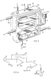
- FIG. 4 A schematic representation of the basic components included in electronic fuel metering unit 31 is shown in FIG. 4.
- engine speed is monitored by tachometer 37 and engine demand, such as imposed by an operator of a motor vehicle, is intermittently and variably expressed through potentiometer 43.
- engine demand such as imposed by an operator of a motor vehicle
- potentiometer 43 Because of the high volatility of the vapor fuel derived from separator 20, the engine is efficiently operated at any given steady state on a lean or higher than stoichiometric air-to-fuel ratio. This is maintained through a lean circuit 143 provided with a resistor 145 disposed therein.
- the signal path is only through circuit 143 to a summing amplifier 147 which in turn activates solenoid valve 29, the latter being variable in operation and provides the desired degree of fuel metering through conduit 19 in accordance with variations in both engine speed and operator demand.
- a summing amplifier 147 which in turn activates solenoid valve 29, the latter being variable in operation and provides the desired degree of fuel metering through conduit 19 in accordance with variations in both engine speed and operator demand.
- a difference in the signals imposed by engine speed and engine demand immediately occurs, which difference is reflected in current supplied by potentiometer 43 to an output transconductance amplifier 149.
- This difference is amplified through an enrichment fuel circuit 151, with the outputs from the lean circuit and enrichment fuel circuit being passed to and added together by amplifier 147.
- the resultant signal then causes valve 29 to meter fuel flow through conduit 19 in direct proportion to the fuel requirement.
- metering unit 153 may be substituted for previously described electronic metering unit 31 and, moreover, comprises a mechanical analog thereof.
- Unit 153 includes a fixed casing 155 provided with a bore 156 within which a tubular valve member 157 is rotatably journaled.
- Valve member 157 is of a cylindrical configuration and is sealed within casing 155 by a pair of gaskets 159 and 161, in the form of O-rings or the like.
- Valve member 157 is provided with a first slot 163 which extends approximately 180° around the wall thereof.
- a second slot 165 Spaced from slot 163 is a second slot 165 having a greater width than slot 163 and also extending approximately 180° around the wall of valve member 157.
- casing 155 is provided with a substantially semicylindrical cavity 167 which communicates with the interior of valve member 157 through slots 163 and 165, the degree of communication being dependent upon the rotational position of valve member 157 with respect to bore 156.
- a plug 169 is secured within valve member 157 through a male threaded portion 171 which engages a corresponding female threaded portion 173 provided in the interior wall of valve member 157.
- Plug 169 includes an enlarged closure head 175 having a diameter corresponding substantially to the internal diameter of valve member 157 and a length that exceeds the width of second slot 165.
- closure head 175 permits varying the degree of communication between the interior of valve member 157 and cavity 167 through second slot 165. This variation in degree of communication is in addition to that afforded by the rotational positioning of valve member 157 within bore 156. It is of course recognized that the direction of corresponding threads 171 and 173 determines whether plug 169 is advanced into or retracted from valve member 157 during the rotation of plug 169 in a given direction, be it clockwise or counterclockwise.
- Rotation of valve member 157 in correlation to engine speed may be achieved through a first pulley wheel 177 mounted on an axle 179 carried by the end of valve member 157 corresponding to first slot 163.
- a coil spring 181 having a first end 183 secured within casing 155 and a second end 185 secured in pulley 177 provides a counter rotative force to pulley 177 so that the latter is always restored to its original position after it has been rotated.
- Rotation of pulley wheel 177 is accomplished through a fluid cylinder assembly 187 which receives vacuum pressure through line 189 from the intake manifold 93 of the engine or other such source of pressure providing a corresponding indication of engine speed.
- a piston rod 191 having an associated piston 193 is disposed for reciprocating movement within a cylinder 195.
- the free end of rod 191 is connected to a flexible belt 197 or the like, which belt 197 is in turn secured around pulley wheel 177.
- actuation of fluid motor 187 causes a corresponding rotative displacement of valve member 157 with respect to casing 155.
- Subsequent deactivation of motor 187 causes spring 181 to restore valve member 157 to its original position with respect to casing 155.
- Rotation of plug 169 is accomplished through a second pulley wheel 201 mounted on a free end 203 of plug 169.
- Rotation of pulley wheel 201 is effected by a flexible belt 205 that engages wheel 201 and is actuated in accordance with operator demand on the engine. In those circumstances where the engine is utilized in a vehicle, belt 205 may be mechanically linked to either the throttle or accelerator linkage.
- a coil spring 207 is provided with a first end 209 secured to a stationary support 211.
- a second end 213 is secured to one end of a flexible cable 215 which is wrapped around free end 203 of plug 169 and has its other end (not shown) secured thereto.
- the force of spring 207 imparted to plug 169 through cable 215 serves to restore the original position of plug 169 after rotative displacement thereof by forces imposed on pulley 201 through flexible belt 205.
- conduit 217 may be either conduit 19 or conduit 97, depending upon the separator device being utilized.
- conduit 217 may be either conduit 19 or conduit 97, depending upon the separator device being utilized.
- the amount of fuel passing from the interior of valve member 157 into cavity 167 is precisely metered in accordance with both engine speed and operator demand.
- Fuel metered by unit 153 is conducted away from cavity 167 through a conduit 219, the latter being either conduit 19 or conduit 97 as shall also be later described.
- separator 221 which comprises an alternative device for incorporation in fuel system 1 in substitution for previously described separator 20.
- Separator 221 includes a pair of fluid motors 223 and 225 which operate in tandem with each other for the purpose of producing a continuous source of light vapor fraction for carburetion into intake manifold 93 of the engine.
- Motor 223 comprises a cylinder 227 within which a piston 229 is disposed for reciprocating movement in association with a piston rod 231.
- a seal 233 is provided at one end of cylinder 227 to prevent escape of fluids therefrom.
- An external seal 235 is provided for sealing and journaling the reciprocating movement of rod 231.
- the extension and the retraction of rod 231 with respect to cylinder 227 serves to sequentially activate a plurality of spaced limit switches 237, 239, 241 and 243. Switches 237 and 239 are maintained in normally closed positions when not contacted by rod 231. Switches 241 and 243 are maintained in normally open positions when not contacted by rod 231.
- cylinder 227 The upper end of cylinder 227 is provided with a positive pressure line 245 for introducing pressurized fluid, such as air pressure from pump 15 or a similar source, into cylinder 227.
- a solenoid valve 247 is disposed in line 245 for controlling fluid flow therethrough into cylinder 227.
- a negative pressure line 249 is provided for supplying vacuum pressure, such as from intake manifold 93 or a similar source, into cylinder 227.
- a solenoid valve 251 controls pressure supplied through line 249.
- a transducer 253 for generating ultrasonic energy within cylinder 227.
- Transducer 253 is operated off of main power supply 103.
- First container 3 supplies fuel to the interior of cylinder 227 through a supply conduit 255.
- a heater 257 which may be of the resistance type or heat exchange variety receiving hot fluids from the engine exhaust manifold, may be disposed in conduit 255 for preheating fuel prior to its introduction into cylinder 227.
- a solenoid valve 259 controls the flow of fuel into cylinder 227 through conduit 255.
- Lighter vapor fractions generated by motor 223 are passed out of cylinder 227 through a light fraction conduit 261, through a solenoid valve 263 disposed therein, through a switching valve 265 and finally through conduit 97 to previously indicated carburetor 87.
- a fuel metering device 269 disposed in conduit 97 controls the amount of light vapor fractions being carbureted into the engine in direct response to operator demand and engine speed.
- Metering device 269 may be either electronic fuel metering unit 31 or mechanical fuel metering unit 153.
- Switching valve 265 is preferably a spool valve having a reciprocating valve member permitting alternate fluid flow through conduit 97 from two sources.
- the heavy liquid fractions produced by motor 223 are passed out a conduit 271 into drain 63 for storage in previously indicated second container 61.
- a solenoid valve 275 is disposed in conduit 271 for controlling the flow of heavier fractions therethrough.
- motor 225 is in fluid communication with motor 223 and includes the same components as the latter.
- a piston (not shown) is also disposed in a cylinder 277 of motor 225 and includes an associated piston rod 279.
- Motor 221 also includes a plurality of limit switches 281, 283, 285 and 287 which function in the exact same manner as previously described switches 237-243 associated with motor 223.
- Rod 279 also includes a journal seal 289.
- motor 225 is provided with a positive pressure line 291 with a solenoid valve 293 disposed therein, and a negative pressure line 295 having a corresponding solenoid valve 297 disposed therein.
- Fuel is also supplied to cylinder 225 from container 3 through common conduit 255.
- conduit 255 feeding fuel motor 225 may also include a heater 299 and solenoid valve 301 for the same corresponding purposes.
- a transducer 303 is disposed at the lower portion of cylinder 227 for generating ultrasonic energy therein, with transducer 303 also being operated off of power supply 81.
- Light vapor fractions produced by motor 225 are sent to regulator valve 265 through a conduit 305 having a solenoid valve 307 disposed therein. Heavier liquid fractions produced by motor 225 are sent to drain 63 through a conduit 309 having a solenoid valve 311 disposed therein.
- separator 221 shall be described with reference to motor 223 only since it is understood that the structural and functional features of motors 223 and 225 are exactly the same with the exception that they operate in opposite and tandem relationship to each other in order to produce a continuous flow of lighter fraction hydrocarbons through conduit 97 to carburetor 87.
- valve 247 closes off positive pressure line 245 and valve 251 is open to permit application of negative pressure through line 249 to the interior of cylinder 227.
- Valve 259 is open to permit fuel from container 3 to flow into cylinder 227 through conduit 255.
- valves 263 and 275 are closed to prevent fluid flow through their respective conduits 261 and 271. Vacuum applied through line 249 from intake manifold 93 by the operation of the engine serves to raise piston 229 and associated rod 231, thereby initiating the upstroke movement of motor 223.
- Transducer 253 is also deactivated when contact is made on switch 243-bv rod 231.
- rod 231 When rod 231 has reached this maximum upstroke position, it then begins its downstroke moyement by virtue of positive pressure being applied to piston 229 from line 245.
- switch 243 When rod 231 passes and closes normally opened switches 241 and 243, there is no valve actuation.
- valye 263 is closed for terminating flow of light vapor fractions through conduit 261.
- valve 275 is opened to permit the heavier liquid fractions produced by motor 223 to flow through conduit 271 and out drain 63. In this position of rod 231, the reciprocating valve member in regulator valve 265 shifts to close off line 261, thereby permitting light vapor fractions from cylinder 277 to pass into conduit 97 from conduit 305 of motor 225.
- fuel system 1 of the present invention is depicted in conjunction with the internal combustion engine of a vehicle and, in this capacity serves to modify and utilize the fuel supply normally carried by the vehicle for its operation.
- the embodiment of system 1 utilizes the separator 20 of FIG. 3, which employs heat from the exhaust manifold of the engine to effect fractionation of the fuel into lighter vapor and heavier liquid fractions.
- separator 20 either electronic fuel metering unit 31 may be incorporated in conduit 19 as shown in FIG. 1 or, alternatively, mechanical fuel metering unit 153 depicted in FIG. 5 may be utilized in place of valve 29 in conduit 19 as a substitute for unit 31. It is therefore apparent that when separator 20 is being utilized, either electronic unit 31 or its mechanical analog unit 153 is disposed upstream of separator 20 to meter unfractionated fuel received from container 3 through conduit 19.
- metering units 31 or 153 may alternatively be utilized in conjunction therewith by disposing the desired unit in conduit 97 for unit 269 as previously indicated in the description of FIG. 7. In this situation, unit 31 or unit 153 is disposed downstream from separator 221 and serves to meter light vapor fraction hydrocarbons directly into carburetcr 87. When separator 221 is utilized, nozzle 99 is not necessary since starting of the engine can be effected from light vapor fractions produced by separator 221. Mode of Operation
- thermostatic control unit 25 which senses the internal temperature of separator 20 through thermal sensors 53 and 55. Since the temperature is low, unit 25 opens solenoid valve 111, thereby permitting fuel from container 3 to be sent to fogging nozzle 99 through conduit 107.
- Secondary power supply 103 is activated and serves to operate the ultrasonic unit associated with nozzle 99 so that fuel may be sprayed as fine droplets into throat 91 of carburetor 87. This serves to start the engine which in turn circulates its hot exhaust gases through separator 20 by way of conduits 45 and 47.
- control unit 25 opens valve 23 and fuel from container 3 is sent through conduit 19 to separator 20.
- the latter fractionates the fuel and sends light vapor fractions to venturi 95 of carburetor 87 to supplement fuel droplets produced by nozzle 99.
- Capacitor 117 then shuts off the operation of nozzle 99 by closing valve 111 and detaching power supply 103.
- the engine then continues to operate from light vapor fractions fed into carburetor 87 through conduit 97.
- electronic metering unit 31 When operator demand increases and the throttle plate of the engine opens, electronic metering unit 31 sends increased current to variable solenoid valve 29 to increase flow of fuel therethrough to separator 20 which in turn provides carburetor 87 with a greater amount of light vapor fractions.
- Unit 31 provides supporting current to permit minimal fuel to be injected in carburetor 87, thereby permitting the engine ignition to occur at any speed.
- Unit 31 also provides supplementary current to permit additional fuel to be injected in the engine to allow momentary enrichment of the air-to-fuel mixture up to the maximum fuel for maximum power at any given engine speed, though always maintaining a lean fuel mixture or higher than stoichiometric air-to-fuel ratio.
- Unit 31 further provides the supplementary current at a rate proportional to the degree operator demand exceeds engine speed at any given time or speed; operator demand being imposed directly through accelerator actuation.
- Separator 20 operates at a control temperature of preferably between about 163-190°C (325°-375°F) if gasoline is the fuel supply being utilized.
- the heavy oily hydrocarbon fractions in liquid form are drained from separator 20 through conduit 63 into second container 61 for storage.
- float indicator 69 actuates switching unit 73 which in turn cuts off power supply 81 from system 1, thereby terminating the operation of system 1 in the same manner as switching off the ignition of the vehicle.
Applications Claiming Priority (1)
| Application Number | Priority Date | Filing Date | Title |
|---|---|---|---|
| PCT/US1984/000114 WO1985003330A1 (en) | 1984-01-27 | 1984-01-27 | Fuel system for internal combustion engines |
Publications (3)
| Publication Number | Publication Date |
|---|---|
| EP0170649A1 EP0170649A1 (en) | 1986-02-12 |
| EP0170649A4 EP0170649A4 (en) | 1986-07-10 |
| EP0170649B1 true EP0170649B1 (en) | 1989-09-27 |
Family
ID=22182023
Family Applications (1)
| Application Number | Title | Priority Date | Filing Date |
|---|---|---|---|
| EP84900923A Expired EP0170649B1 (en) | 1984-01-27 | 1984-01-27 | Fuel system for internal combustion engines |
Country Status (9)
| Country | Link |
|---|---|
| EP (1) | EP0170649B1 (da) |
| JP (1) | JPS61501040A (da) |
| AU (1) | AU564545B2 (da) |
| BR (1) | BR8407274A (da) |
| DE (1) | DE3479910D1 (da) |
| DK (1) | DK436885D0 (da) |
| FI (1) | FI853709A0 (da) |
| NO (1) | NO853804L (da) |
| WO (1) | WO1985003330A1 (da) |
Families Citing this family (3)
| Publication number | Priority date | Publication date | Assignee | Title |
|---|---|---|---|---|
| US4667643A (en) * | 1985-12-02 | 1987-05-26 | International Mileage Master, Ltd. | Heated fuel vapourizer and slidable throttle valve |
| IE67000B1 (en) * | 1990-09-19 | 1996-02-21 | Wardoken Holdings Limited | Internal combustion engines |
| ES2094235T3 (es) * | 1990-11-23 | 1997-01-16 | Arumadura Nandasena Kulasinghe | Combustion de combustibles liquidos. |
Family Cites Families (16)
| Publication number | Priority date | Publication date | Assignee | Title |
|---|---|---|---|---|
| US2732835A (en) * | 1956-01-31 | Ultrasonic | ||
| US860522A (en) * | 1906-07-14 | 1907-07-16 | William Brown | Carbureter. |
| FR612067A (fr) * | 1923-10-29 | 1926-10-16 | Appareil de vaporisation du pétrole | |
| DE473369C (de) * | 1927-03-14 | 1929-03-14 | Alexander Jezekil Liberman | Sicherungsvorrichtung gegen Flammenrueckschlaege |
| FR750867A (fr) * | 1932-02-16 | 1933-08-21 | Procédé et appareil pour la marche des moteurs à combustion interne avec un combustible liquide à point d'ébullition élevé | |
| US1980496A (en) * | 1933-06-24 | 1934-11-13 | Leslie E Crouch | Low grade fuel vaporizer for internal combustion engines |
| FR840643A (fr) * | 1938-01-03 | 1939-04-28 | Procédé et appareil pour l'alimentation en air et vapeurs hydrocarburées des moteurs à explosion | |
| FR889166A (fr) * | 1942-02-05 | 1944-01-03 | Dispositif d'alimentation de moteur à combustion interne et ses éléments | |
| US3167059A (en) * | 1961-11-21 | 1965-01-26 | Love John | Auxiliary valves for internal combustion engines |
| JPS5325723A (en) * | 1976-08-21 | 1978-03-09 | Masao Yamazaki | Carburettor used of supersonic wave |
| US4151821A (en) * | 1976-12-06 | 1979-05-01 | Edward P Goodrum | Engine fuel supply system |
| US4177779A (en) * | 1977-07-20 | 1979-12-11 | Ogle Thomas H W W P | Fuel economy system for an internal combustion engine |
| US4178897A (en) * | 1977-10-20 | 1979-12-18 | Omnewtronics, Inc. | System and method of feeding gasoline fuel into an internal combustion engine |
| JPS5818548A (ja) * | 1981-07-27 | 1983-02-03 | Tokyo Tatsuno Co Ltd | 自動車 |
| JPS5849424U (ja) * | 1981-09-28 | 1983-04-04 | 東芝ライテック株式会社 | 放電灯点灯装置用安定器 |
| GB2120724B (en) * | 1982-05-14 | 1985-07-17 | Edward Lee Simonds | Air/fuel mixing device for an i c engine with exhaust heated vaporiser |
-
1984
- 1984-01-27 WO PCT/US1984/000114 patent/WO1985003330A1/en active IP Right Grant
- 1984-01-27 EP EP84900923A patent/EP0170649B1/en not_active Expired
- 1984-01-27 JP JP59500912A patent/JPS61501040A/ja active Pending
- 1984-01-27 DE DE8484900923T patent/DE3479910D1/de not_active Expired
- 1984-01-27 AU AU25744/84A patent/AU564545B2/en not_active Ceased
- 1984-01-27 BR BR8407274A patent/BR8407274A/pt not_active IP Right Cessation
-
1985
- 1985-09-26 DK DK436885A patent/DK436885D0/da not_active Application Discontinuation
- 1985-09-26 FI FI853709A patent/FI853709A0/fi not_active Application Discontinuation
- 1985-09-27 NO NO853804A patent/NO853804L/no unknown
Also Published As
| Publication number | Publication date |
|---|---|
| NO853804L (no) | 1985-09-27 |
| FI853709L (fi) | 1985-09-26 |
| FI853709A0 (fi) | 1985-09-26 |
| DK436885A (da) | 1985-09-26 |
| JPS61501040A (ja) | 1986-05-22 |
| EP0170649A1 (en) | 1986-02-12 |
| DE3479910D1 (en) | 1989-11-02 |
| AU2574484A (en) | 1985-08-09 |
| EP0170649A4 (en) | 1986-07-10 |
| AU564545B2 (en) | 1987-08-13 |
| BR8407274A (pt) | 1986-01-21 |
| WO1985003330A1 (en) | 1985-08-01 |
| DK436885D0 (da) | 1985-09-26 |
Similar Documents
| Publication | Publication Date | Title |
|---|---|---|
| US4429675A (en) | Fuel system for internal combustion engines | |
| US4151821A (en) | Engine fuel supply system | |
| US4112889A (en) | Fuel system and vaporizer for internal combustion engines | |
| EP0086439B1 (en) | Hydrogen gas injector system for internal combustion engine | |
| US4640234A (en) | Method of running an internal combustion engine with alternative fuels | |
| US4483305A (en) | Fuel vaporization device | |
| US4114566A (en) | Hot fuel gas generator | |
| US4375799A (en) | Fuel vaporization system | |
| US4068639A (en) | Automobile engine economizer | |
| US5398663A (en) | Combustion of liquid fuels | |
| US6843236B1 (en) | Multi-phase fuel system | |
| US4781165A (en) | Internal combustion engine pollutant control system | |
| US4197819A (en) | Hot fuel gas generator | |
| US20040089277A1 (en) | Parallel vaporized fuel system | |
| US4153653A (en) | Fuel induction system for internal combustion engines | |
| US4213432A (en) | Device for vaporizing liquid hydrocarbon fuel | |
| EP0170649B1 (en) | Fuel system for internal combustion engines | |
| PL170039B1 (pl) | Sposób pracy silnika spalinowego typu silnika tlokowego oraz silnik spalinowytypu silnika tlokowego PL PL PL PL PL | |
| US4359996A (en) | System for preparing hot vaporized fuel for use in internal combustion engine | |
| CA1042294A (en) | Fuel metering device for internal combustion engines and fuel systems incorporating such devices | |
| US4452215A (en) | Fuel system for internal combustion engines | |
| US4325343A (en) | Fuel metering system | |
| CA1202536A (en) | Fuel system for internal combustion engines | |
| WO1990010150A1 (en) | Water vaporiser | |
| US20110041813A1 (en) | Supply device for internal combustion engine |
Legal Events
| Date | Code | Title | Description |
|---|---|---|---|
| PUAI | Public reference made under article 153(3) epc to a published international application that has entered the european phase |
Free format text: ORIGINAL CODE: 0009012 |
|
| AK | Designated contracting states |
Kind code of ref document: A1 Designated state(s): BE CH DE FR GB LI NL Designated state(s): BE CH DE FR GB LI NL |
|
| 17P | Request for examination filed |
Effective date: 19860103 |
|
| RBV | Designated contracting states (corrected) |
Designated state(s): BE CH DE FR GB LI NL SE |
|
| A4 | Supplementary search report drawn up and despatched |
Effective date: 19860710 |
|
| 17Q | First examination report despatched |
Effective date: 19871005 |
|
| GRAA | (expected) grant |
Free format text: ORIGINAL CODE: 0009210 |
|
| AK | Designated contracting states |
Kind code of ref document: B1 Designated state(s): BE CH DE FR GB LI NL SE |
|
| REF | Corresponds to: |
Ref document number: 3479910 Country of ref document: DE Date of ref document: 19891102 |
|
| ET | Fr: translation filed | ||
| PLBE | No opposition filed within time limit |
Free format text: ORIGINAL CODE: 0009261 |
|
| STAA | Information on the status of an ep patent application or granted ep patent |
Free format text: STATUS: NO OPPOSITION FILED WITHIN TIME LIMIT |
|
| 26N | No opposition filed | ||
| PGFP | Annual fee paid to national office [announced via postgrant information from national office to epo] |
Ref country code: GB Payment date: 19901231 Year of fee payment: 8 |
|
| PGFP | Annual fee paid to national office [announced via postgrant information from national office to epo] |
Ref country code: SE Payment date: 19910102 Year of fee payment: 8 |
|
| PGFP | Annual fee paid to national office [announced via postgrant information from national office to epo] |
Ref country code: FR Payment date: 19910117 Year of fee payment: 8 |
|
| PGFP | Annual fee paid to national office [announced via postgrant information from national office to epo] |
Ref country code: DE Payment date: 19910130 Year of fee payment: 8 |
|
| PGFP | Annual fee paid to national office [announced via postgrant information from national office to epo] |
Ref country code: NL Payment date: 19910131 Year of fee payment: 8 |
|
| PGFP | Annual fee paid to national office [announced via postgrant information from national office to epo] |
Ref country code: CH Payment date: 19910408 Year of fee payment: 8 |
|
| PGFP | Annual fee paid to national office [announced via postgrant information from national office to epo] |
Ref country code: BE Payment date: 19910626 Year of fee payment: 8 |
|
| PG25 | Lapsed in a contracting state [announced via postgrant information from national office to epo] |
Ref country code: GB Effective date: 19920127 |
|
| PG25 | Lapsed in a contracting state [announced via postgrant information from national office to epo] |
Ref country code: SE Effective date: 19920128 |
|
| PG25 | Lapsed in a contracting state [announced via postgrant information from national office to epo] |
Ref country code: LI Effective date: 19920131 Ref country code: CH Effective date: 19920131 Ref country code: BE Effective date: 19920131 |
|
| NLS | Nl: assignments of ep-patents |
Owner name: TALBERT FUEL SYSTEMS, INC. TE ALLENTOWN, PENNSYLVA |
|
| REG | Reference to a national code |
Ref country code: FR Ref legal event code: TP |
|
| REG | Reference to a national code |
Ref country code: GB Ref legal event code: 732 |
|
| BERE | Be: lapsed |
Owner name: TALBERT FUEL SYSTEMS INC. Effective date: 19920131 |
|
| PG25 | Lapsed in a contracting state [announced via postgrant information from national office to epo] |
Ref country code: NL Effective date: 19920801 |
|
| NLV4 | Nl: lapsed or anulled due to non-payment of the annual fee | ||
| GBPC | Gb: european patent ceased through non-payment of renewal fee | ||
| PG25 | Lapsed in a contracting state [announced via postgrant information from national office to epo] |
Ref country code: FR Effective date: 19920930 |
|
| REG | Reference to a national code |
Ref country code: CH Ref legal event code: PL |
|
| PG25 | Lapsed in a contracting state [announced via postgrant information from national office to epo] |
Ref country code: DE Effective date: 19921001 |
|
| REG | Reference to a national code |
Ref country code: FR Ref legal event code: ST |
|
| EUG | Se: european patent has lapsed |
Ref document number: 84900923.8 Effective date: 19920806 |