EP0170548B1 - Méthode et perfectionnement aux outils de forage permettant une grande efficacité du nettoyage du front de taille - Google Patents
Méthode et perfectionnement aux outils de forage permettant une grande efficacité du nettoyage du front de taille Download PDFInfo
- Publication number
- EP0170548B1 EP0170548B1 EP85401183A EP85401183A EP0170548B1 EP 0170548 B1 EP0170548 B1 EP 0170548B1 EP 85401183 A EP85401183 A EP 85401183A EP 85401183 A EP85401183 A EP 85401183A EP 0170548 B1 EP0170548 B1 EP 0170548B1
- Authority
- EP
- European Patent Office
- Prior art keywords
- tool
- axis
- jet
- central part
- plane
- Prior art date
- Legal status (The legal status is an assumption and is not a legal conclusion. Google has not performed a legal analysis and makes no representation as to the accuracy of the status listed.)
- Expired
Links
Images


Classifications
-
- E—FIXED CONSTRUCTIONS
- E21—EARTH DRILLING; MINING
- E21B—EARTH DRILLING, e.g. DEEP DRILLING; OBTAINING OIL, GAS, WATER, SOLUBLE OR MELTABLE MATERIALS OR A SLURRY OF MINERALS FROM WELLS
- E21B10/00—Drill bits
- E21B10/60—Drill bits characterised by conduits or nozzles for drilling fluids
- E21B10/61—Drill bits characterised by conduits or nozzles for drilling fluids characterised by the nozzle structure
-
- E—FIXED CONSTRUCTIONS
- E21—EARTH DRILLING; MINING
- E21B—EARTH DRILLING, e.g. DEEP DRILLING; OBTAINING OIL, GAS, WATER, SOLUBLE OR MELTABLE MATERIALS OR A SLURRY OF MINERALS FROM WELLS
- E21B10/00—Drill bits
- E21B10/60—Drill bits characterised by conduits or nozzles for drilling fluids
Definitions
- the present invention relates to an improved rotary drilling tool with high efficiency for cleaning the working face.
- Rotary drilling tools are already known comprising a body, a first end of which is connected to rotation drive means and the second end of which defines the cutting face. Such tools are described in American patents US-A-3,645,346, US-A-4,323,130 and US-A-3,838,742 and British GB-A-2,047,308.
- the tool described in US-A-4 323 130 has a single central nozzle making an angle of 30 ° relative to the axis of the tool.
- a disadvantage of the prior art lies in the fact that the distribution currently adopted for these jets is not favorable to good cleaning of the central part of the tool, which limits the performance in forward speed of the tool and increases wear.
- the object of the present invention is to propose an improvement to the drilling tools so as to increase the performance thereof by a more efficient sweeping of the cuttings on the cutting face and more particularly in the central part, or central zone, of the tool.
- the present invention can be applied to drilling tools or drill bits working by chip removal (blade tool) or by abrasion.
- the first tools mentioned generally include polycrystalline synthetic diamond cutting elements, the second generally include natural diamonds.
- This objective is obtained according to the present invention, by orienting at least one jet inclined preferentially towards the central part of the tool, the other jets not coming to interfere with this first jet.
- speed is generally understood to mean the average speed obtained from the integration of speeds over the shortest distance separating the tool from the geological formation.
- the jet (s) preferably oriented towards the central part of the tool must be positioned so that the vector obtained by the orthogonal projection on a plane perpendicular to the axis of the tool of the speed of flow in the central part of the tool is not zero.
- This vector will be called the effective speed vector.
- This or these jets preferably oriented towards the central part of the tool will advantageously be associated with one or more jets whose flow preferably moves away from the central part of the tool, this or these jets not being on the line segment passing through the axis of the tool and the starting point of a jet preferentially oriented towards the central part of the tool; this line segment mentioned above is limited by the axis of the tool and by the starting point of the jet preferentially oriented towards the central part of the tool.
- the present invention relates to a method improving the clearance of a rotary drilling tool, in particular on itself in operation, around a proper axis, or axis of the tool.
- This tool comprises a body, a first end of which is adapted to be connected to rotary drive means and the second end of which defines the cutting face, the area of the second end close to said axis is called the central part of the tool.
- the tool has at least one nozzle.
- the central part, or central zone of the tool is defined by the part of the tool close to the center of the tool. This center is itself defined as the intersection of the tool's own axis with the exterior surface of the tool.
- the method according to the invention is further characterized in that said nozzle is positioned to produce a flow oriented towards the central part of the tool, the vector obtained by the orthogonal projection on a plane perpendicular to the axis of the tool the speed of said flow in the central part of the tool being non-zero at any point of the central part of the tool. Said vector will be qualified as an effective speed vector as has already been mentioned previously.
- the present invention is characterized in that the tool comprises at least one additional nozzle adapted to produce flows having a non-zero tangential velocity component, relative to a circle centered on a point belonging to the axis of the tool.
- the method according to the invention can be applied to the case of a tool comprising several nozzles.
- these nozzles are positioned and dimensioned to produce a resulting flow in the center of the tool, the effective velocity vector of which is not zero at any point in the central part of the tool.
- the nozzle or nozzles are positioned such that there is at least one axis, called the axis of circulation, belonging to the plane perpendicular to the axis of the tool.
- the orthogonal projections on this axis of the different effective speed vectors of the central part of the tool are called traffic vectors.
- all of the traffic vectors are oriented in the same direction.
- said axis can be a curved line. But preferably, it will be a straight axis passing through the axis of the tool.
- the present invention also relates to a drilling tool for implementing the method and these variants described above.
- This tool is characterized in that it comprises in combination at least a first injection nozzle positioned at a first location of the tool, said nozzle comprising an injection channel whose axis is oriented substantially towards the central zone of the tool and at least one additional nozzle adapted to produce flows having a non-zero tangential velocity component with respect to a circle centered on a point belonging to the axis of the tool.
- the tool according to the invention may comprise at least one second nozzle positioned on the side of the tool opposite to that containing the first nozzle, said opposite side being defined by the portion of the tool located in the half-space delimited by a first plane passing through the axis of the tool, perpendicular to a second plane containing a point of the injection orifice of said first nozzle as well as the axis of the tool and not containing not said first nozzle, said nozzle comprising an injection channel adapted to produce a flow substantially oriented in the direction opposite to that defined by the central zone of the tool.
- the second injection nozzle can be positioned on the tool substantially in a half-plane belonging to the second plane, this half-plane being delimited by the axis of the tool and does not contain the first nozzle .
- the tool can comprise several fluid injection nozzles having fluid injection channels whose axis is oriented towards the central zone of the tool. These nozzles being positioned on the tool on the same side with respect to a plane passing through the axis of the tool.
- the tool may include a third nozzle comprising a third channel, said third nozzle being positioned substantially in the vicinity of said first nozzle, the axis of said third channel being oriented substantially in the opposite direction to that of the first nozzle .
- the reference 1 designates as a whole the body of the drilling tool or drill bit according to the invention which will, for example, be made of special steel. At a first of its ends, this tool is adapted to be connected to rotary drive means, for example by means of a thread 2.
- These drive means of the rotary tool will include a holder tool of which the drill bit is made integral, and which is part of the rotary drilling column, or which can be directly driven in rotation by the rotor of a downhole motor.
- the second end or head 3 of the drill bit has a face delimiting the cutting face of the tool, this face comprising a plurality of means 4 for destroying the formation to be drilled.
- the reference 5 represents the axis of the tool and the reference 6 represents the central part or central zone, of the tool which can be delimited for example by the part of the surface of the second end of the tool included inside a cylinder whose axis coincides with the axis of the tool 5 and whose diameter is equal to the outside diameter of the tool divided by three.
- the cleaning of the cuttings and their evacuation is done by a circulation of the drilling fluid which is brought by the drill string as far as the interior cavity 7 of the drill bit.
- the fluid is then distributed through a bore 16 to at least one first nozzle 9 having a fluid injection channel whose axis 17 is oriented substantially towards the central zone 6 of the tool.
- injection nozzle means the part of the nozzle which will orient the direction of the jet, thus in FIG. 2, the channel of nozzle 18 corresponds to passage 19.
- the axis 20 of the channel 19 of nozzle 18 can be defined as the direction resulting from the flow, or jet, produced by this channel 19.
- the axis 20 of the channel 19 of the nozzle 18 is assumed to be oriented in the direction of the flow produced by the nozzle, this direction is indicated in FIG. 2 by the arrow 22.
- the fluid from the nozzle 9 is discharged through the ring finger 8 (Fig. 1).
- the drill bit 1 in FIG. 1 has a second nozzle 23 which has an axis 24 oriented towards the ring finger 8.
- This second nozzle is located on the side of the drill bit 25 opposite to that containing the first nozzle and which bears the reference 26.
- the so-called opposite side 25 is defined by the portion of the tool situated in the half-space delimited by a first plane passing through the axis of the tool perpendicular to a second plane containing a point of the injection orifice of the first nozzle 9 as well as the drill bit axis and which does not contain the first nozzle 9.
- the second plane corresponds to the plane of the figure herself.
- the drill bit in FIG. 1 has a third nozzle 27 which can be supplied by the same bore 16 as that which supplies the first nozzle 9.
- the axis 28 of the channel of this third nozzle 27 is oriented substantially in the direction opposite to that of the first nozzle. It should be understood by this that the third nozzle 27 has a fluid injection channel which creates a flow moving away from the plane perpendicular to the axis 17 of the first channel.
- the third nozzle 27 can be supplied by an independent bore different from that feeding the first nozzle 9.
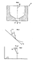
- the reference 11 represents the cutting face as it is machined by the tool.
- Reference 12 represents the plane tangent to the working face at the point of impact of the jet f on the latter.
- the reference 13 represents the plane tangent to the working face at the point closest to the nozzle from which the jet f originates.
- the reference 14 is the projection oriented in the direction of progression of the axis of the tool 5 on the plane 13.
- the reference 15 designates the projection of the trajectory of the jet f at the outlet of the nozzle in projection on the plane 13. is the angle formed by the projections 14 and 15. The angle is calculated starting from the half-line AB where A is the point of intersection of the projections 14 and 15.
- the jets used are jets inclined with respect to the working face, so that the angle a formed by the jet f with the plane tangent 12 to the working face at the point of impact of this jet is different from 90 °.
- a jet preferentially oriented towards the central part of the tool is called any jet coming from a nozzle external to this central part 6 and the orthogonal projection of the trajectory on a plane perpendicular to the axis 5 of the tool. is partly in the orthogonal projection on this plane of the central part 6 of the tool.
- a jet is called a jet oriented preferentially towards the central part of the tool when the angle ⁇ defined in FIG. 4 has a value less than 90 °.
- the drill bit 29 comprises a single nozzle 30 of oblong shape (FIG. 5).
- the plane of this figure corresponds to a plane perpendicular to the axis of the tool 20.
- the axis 38 represents the axis of circulation of the fluid.
- the arrow 39 represents an effective velocity vector obtained by the orthogonal projection on the plane of the figure of a velocity vector of the flow in the central part of the tool 33.
- the circle 40 represents the orthogonal projection on the plane of the figure of the limit of the central area 33.
- the reference 41 designates the circulation vector obtained by the orthogonal projection of the effective speed vector 39 on the circulation axis 38.
- the circulation vector 41 can be obtained directly by projecting, along a plane perpendicular to the circulation axis 38, the speed of the flow on the circulation axis 38.
- the different circulation vectors of the central part of the tool are oriented in the same direction.
- the application of the invention leads to the best efficiency when all the jets are inclined relative to the working face, but it retains its value when one or more jets are not inclined relative to the working face.
- the value of the angle a for an inclined jet will advantageously be less than 45 °.
- the value of the angle for a jet preferentially oriented towards the central part of the tool will advantageously be less than 45 °.
- the jets preferably oriented towards the central part of the tool will preferably be located on the same side of a plane passing through the axis 5 of the tool in order to prevent these jets from annihilating themselves in the central part of the tool.
- FIG. 6 shows a possible application of the present invention allowing good cleaning of the tool and the cutting face.
- This tool comprises a nozzle 31 creating a jet 32 oriented towards the central part 33 of the tool and whose essential function is to properly clean said central part 33.
- the nozzles 34 create jets 35 which are not oriented towards the central part of the tool 33 and whose essential function is to clean the surface of the tool in contact with the cutting face, this surface not including the central part of the tool.
- the nozzles 34 create a centrifugal rotating flow which is particularly effective for cleaning the tool and in particular its periphery.
- the nozzles positioned on the tool can be removable or fixed, of identical or different section.
- the fixed nozzles can be formed by a simple channel made directly in the body of the tool and having an appropriate inclination of the injection orifice.
- the sum of the sections of the jets preferentially oriented towards the central part of the tool will preferably be greater than or equal to one third of the total section ST of passage of the nozzles placed on the tool and preferably less or equal to two-thirds of the ST section.
- FIG. 7 represents a diagram showing the gain brought by the invention on the capacity of the drilling tool to evacuate the cuttings which it creates at the bottom of the drilling well.
- the ordinate axis 10 of this diagram represents the capacity of a tool to remove the cuttings.
- the abscissa axis 21 represents the time during which a drilling fluid is passed through the tool.
- the reference 36 corresponds to the performance curve of a tool according to the present invention and the reference 37 corresponds to the performance curve of a tool according to the prior art.
- the tool is placed in a cell simulating the bottom of the wellbore. Between the tool and the cell, a given volume V of sand simulating the cuttings is introduced.
- a fluid is circulated at a given flow rate through the tool and, as a function of time, the volume of cuttings evacuated is recorded relative to the volume of cuttings initially placed in the cell.
- the capacity of the tool to remove the cuttings corresponds to the ratio of the volume of cuttings removed to the initial volume of cuttings V.
- the tool In the case of the tool according to the invention, the cuttings being quickly removed from the cutting face, the tool is therefore permanently in contact with the rock to be destroyed and not in contact with the cuttings it has just created. .
- This has the consequence of increasing the speed of advance of the drilling tool by avoiding the regrinding of the cuttings by this tool, this regrinding limits the effectiveness of the tool and causes initial wear of the latter.
- the performance curve 37 of a tool according to the prior art substantially reaches a horizontal asymptote corresponding to a removal capacity of the cuttings of the order of 80%, which means that the cuttings remaining, ie almost 20% of the initial cuttings are very difficult to remove.
- the tool according to the present invention leaves practically no more cuttings in the cell, due in particular to good cleaning of the central part of the tool.
Description
- La présente invention concerne un outil de forage rotatif amélioré à grande efficacité du nettoyage du front de taille.
- On connait déjà des outils de forage rotatifs comportant un corps dont une première extrémité se raccorde à des moyens d'entraînement en rotation et dont la seconde extrémité délimite le front de taille. De tels outils sont décrits dans les brevets américains US-A-3 645 346, US-A-4 323.130 et US-A-3 838 742 et britannique GB-A-2 047 308.
- L'outil décrit dans le brevet US-A-4 323 130 présente une seule duse centrale faisant un angle de 30° par rapport à l'axe de l'outil.
- On sait également réaliser une amélioration du nettoyage du front de taille et de l'évacuation des déblais en positionnant des duses dont les jets sont inclinés par rapport au front de taille et percutent donc la paroi sous un angle d'incidence différent de 90°.
- Un inconvénient de l'art antérieur réside dans le fait que la répartition actuellement adoptée pour ces jets n'est pas favorable à un bon nettoyage de la partie centrale de l'outil, ce qui limite les performances en vitesse d'avancement de l'outil et en augmente l'usure.
- L'objet de la présente invention est de proposer une amélioration aux outils de forage de manière à en accroître les performances par un balayage plus efficace des déblais sur le front de taille et plus particulièrement dans la partie centrale, ou zone centrale, de l'outil.
- La présente invention peut être appliquée à des outils de forage ou trépans travaillant par enlèvement de copeaux (outil à lames) ou par abrasion. Les premiers outils mentionnés comportent généralement des éléments de coupe en diamant synthétique polycristallin, les seconds comportent généralement des diamants naturels.
- Cet objectif est obtenu selon la présente invention, en orientant au moins un jet incliné de façon préférentielle vers la partie centrale de l'outil les autres jets ne venant pas contrarier ce premier jet.
- Dans le présent texte, on désigne généralement par vitesse, la vitesse moyenne obtenue à partir de l'intégration des vitesses sur la plus courte distance séparant l'outil de la formation géologique.
- Le ou les jets orientés préférentiellement vers la partie centrale de l'outil doivent être positionnés de façon à ce que le vecteur obtenu par la projection orthogonale sur un plan perpendiculaire à l'axe de l'outil de la vitesse de l'écoulement dans la partie centrale de l'outil soit non nul. Ce vecteur sera dit vecteur de vitesse efficace. A ce ou ces jets orientés préférentiellement vers la partie centrale de l'outil seront avantageusement associés un ou plusieurs jets dont l'écoulement s'éloigne de façon préférentielle de la partie centrale de l'outil, ce ou ces jets ne se trouvant pas sur le segment de droite passant par l'axe de l'outil et le point de départ d'un jet orienté préférentiellement vers la partie centrale de l'outil; ce segment de droite sus-mentionné est limité par l'axe de l'outil et par le point de départ du jet orienté préférentiellement vers la partie centrale de l'outil.
- Ainsi, la présente invention concerne une méthode améliorant le déblaiement d'un outil de forage tournant, notamment sur lui-même en fonctionnement, autour d'un axe propre, ou axe de l'outil. Cet outil comporte un corps dont une première extrémité est adaptée à se raccorder à des moyens d'entraînement en rotation et dont la seconde extrémité délimite le front de taille, la zone de la seconde extrémité voisine dudit axe est appelée partie centrale de l'outil, l'outil comporte au moins une duse.
- Plus exactement, la partie centrale, ou zone centrale de l'outil est définie par la partie de l'outil voisine du centre de l'outil. Ce centre est lui-même défini comme étant l'intersection de l'axe propre de l'outil avec la surface extérieure de l'outil.
- La méthode selon l'invention est caractérisée de plus en ce que ladite duse est positionnée pour produire un écoulement orienté vers la partie centrale de l'outil, le vecteur obtenu par la projection orthogonale sur un plan perpendiculaire à l'axe de l'outil de la vitesse dudit écoulement dans la partie centrale de l'outil étant non nul en tout point de la partie centrale de l'outil. Ledit vecteur sera qualifié de vecteur de vitesse efficace comme cela a déjà été mentionne précédemment. La présente invention se caractérise en ce que l'outil comporte au moins une duse supplémentaire adaptée à produire des écoulements ayant une composante de vitesse tangentielle non nulle, par rapport à un cercle centré sur un point appartenant à l'axe de l'outil.
- La méthode selon l'invention peut s'appliquer au cas d'un outil comportant plusieurs duses. Dans ce cas ces duses sont positionnées et dimensionnées pour produire un écoulement résultant au centre de l'outil dont le vecteur de vitesse efficace est non nul en tout point de la partie centrale de l'outil.
- Suivant une variante de la méthode selon l'invention, la ou les duses sont positionnés de telle sorte qu'il existe au moins un axe, dit axe de circulation, appartenant au plan perpendiculaire à l'axe de l'outil. Les projections orthogonales sur cet axe des différents vecteurs de vitesse efficace de la partie centrale de l'outil sont appelés vecteurs de circulation. Selon la présente variante, tous les vecteurs de circulation sont orientés dans le même sens.
- Bien entendu, ledit axe peut être une ligne courbe. Mais de preférence, il s'agira d'un axe droit passant par l'axe de l'outil.
- La présente invention concerne également un outil de forage pour la mise en oeuvre de la méthode et de ces variantes exposées precédemment.
- Cet outil est caractérisé en ce qu'il comporte en combinaison au moins une première duse d'injection positionnée en un premier endroit de l'outil, ladite duse comportant un canal d'injection dont l'axe est orienté sensiblement vers la zone centrale de l'outil et au moins une duse supplémentaire adaptée à produire des écoulements ayant une composante de vitesse tangentielle non nulle par rapport a un cercle centré sur un point appartenant à l'axe de l'outil.
- Selon une variante de réalisation, l'outil selon l'invention peut comporter au moins une deuxième duse positionnée sur le côté de l'outil opposé à celui contenant la première duse, ledit côté opposé étant défini par la portion de l'outil située dans le demi-espace délimité par un premier plan passant par l'axe de l'outil, perpendiculaire à un deuxième plan contenant un point de l'orifice d'injection de ladite première duse ainsi que l'axe de l'outil et ne contenant pas ladite première duse, ladite duse comprenant un canal d'injection adapté à produire un écoulement sensiblement orienté dans la direction opposée à celle définie par la zone centrale de l'outil.
- Selon une autre variante, la deuxième duse d'injection peut être positionnée sur l'outil sensiblement dans un demi-plan appartenant au deuxième plan, ce demi-plan étant délimité par l'axe de l'outil et ne contient pas la première duse.
- Selon une autre variante, l'outil peut comporter plusieurs duses d'injection de fluide ayant des canaux d'injection de fluide dont l'axe est orienté vers la zone centrale de l'outil. Ces duses étant positionnées sur l'outil d'un même côté par rapport à un plan passant par l'axe de l'outil.
- Selon une autre variante, l'outil peut comporter une troisième duse comportant un troisième canal, ladite troisième duse étant positionnée sensiblement au voisinage de ladite première duse, l'axe dudit troisième canal étant orienté sensiblement dans le sens opposé à celui de la première duse.
- La présente invention sera mieux comprise et ses avantages apparaîtront plus clairement à la description qui suit d'un exemple particulier, nullement limitatif illustré par les figures ci- annexées parmi lesquelles:
- - la figure 1 représente un outil de forage comportant des améliorations selon la présente invention,
- - la figure 2 montre une duse,
- - les figures 3 et 4 représentent des schémas permettant de définir différents angles,
- - la figure 5 représente un outil comportant une duse de forme allongée,
- - la figure 6 représente un outil de forage comportant plusieurs duses,
- - la figure 7 représente un diagramme comparatif de l'efficacité d'un outil selon l'art antérieur et d'un outil selon la presente invention.
- Sur la figure 1, la référence 1 désigne dans son ensemble le corps de l'outil de forage ou trépan selon l'invention qui sera, par exemple, réalisé en acier spécial. A une première de ses extrémités, cet outil est adapté à se raccorder à des moyens d'entraînement en rotation, par exemple par l'intermédiaire d'un filetage 2. Ces moyens d'entraînement de l'outil en rotation comprendront un porte-outil dont le trépan est rendu solidaire, et qui fait partie de la colonne de forage rotary, ou qui peut être directement entrainé en rotation par le rotor d'un moteur de fond.
- La seconde extrémité ou tête 3 du trépan comporte une face délimitant le front de taille de l'outil, cette face comportant une pluralité de moyens de destruction 4 de la formation à forer.
- La référence 5 représente l'axe de l'outil et la référence 6 représente la partie centrale ou zone centrale, de l'outil qui peut être délimitée à titre d'exemple par la partie de la surface de la seconde extrémité de l'outil comprise à l'intérieur d'un cylindre dont l'axe coïncide avec l'axe de l'outil 5 et dont le diamètre est égal au diamètre extérieur de l'outil divisé par trois.
- Le nettoyage des déblais et leur évacuation se font par une circulation du fluide de forage qui est amené par le train de tiges jusque dans la cavité intérieure 7 du trépan. Le fluide est ensuite distribué gràce à un percage 16 à au moins une première duse 9 ayant un canal d'injection du fluide dont l'axe 17 est orienté sensiblement vers la zone centrale 6 de l'outil.
- Dans la présente description, on entend par canal d'injection de la duse la partie de la duse qui va orienter la direction du jet, ainsi sur la figure 2, le canal de la duse 18 correspond au passage 19. L'axe 20 du canal 19 de la duse 18 peut être défini comme la direction résultante de l'écoulement, ou du jet, produit par ce canal 19.
- Dans la présente description, l'axe 20 du canal 19 de la duse 18 est supposé être orienté dans le sens de l'écoulent produit par la duse, ce sens est indiqué sur la figure 2 par la flèche 22.
- Il est bien évident que l'on ne sortira pas du cadre de la présente invention en utilisant des duses ayant des sections de passage de diverses formes, ce qui demeure important étant la direction et plus exactement l'orientation de l'axe de ces duses telles que définies précédemment.
- Le fluide issu de la duse 9 est évacué par l'annulaire 8 (Fig. 1).
- Le trépan 1 de la figure 1 comporte une deuxième duse 23 qui possède un axe 24 orienté vers l'annulaire 8.
- Cette deuxième duse est située du côté du trépan 25 opposé à celui contenant la première duse et qui porte la référence 26.
- Le côté dit opposé 25 est défini par la portion de l'outil située dans le demi-espace délimité par un premier plan passant par l'axe de l'outil perpendiculaire à un deuxième plan contenant un point de l'orifice d'injection de la première duse 9 ainsi que l'axe du trépan et qui ne contient pas la première duse 9. Dans le cas de la figure 1, le deuxième plan correspond au plan de la figure elle-même.
- Le trépan de la figure 1 comporte une troisième duse 27 qui peut être alimentée par le même perçage 16 que celui qui alimente la première duse 9.
- L'axe 28 du canal de cette troisième duse 27 est orienté sensiblement dans la direction opposée à celle de la première duse. Il faut comprendre par là que la troisième duse 27 possède un canal d'injection de fluide qui crée un écoulement s'éloignant du plan perpendiculaire à l'axe 17 du premier canal.
- Bien entendu, la troisième duse 27 peut être alimentée par un perçage indépendant différent de celui alimentant la première duse 9.
- On ne sortira pas du cadre de la présente invention si au moins l'une des duses citées précédemment produit un jet qui, dès sa sortie de ladite duse, est parallèle au front de taille et/ou à la surface de l'outil. Ceci revient à dire que l'axe de ladite duse est parallèle au front de taille et/ou à la surface de coupe de l'outil.
- Sur la figure 3, la référence 11 représente le front de taille tel qu'il est usiné par l'outil. La référence 12 représente le plan tangent au front de taille au point d'impact du jet f sur ce dernier.
- Sur la figure 4, la référence 13 représente le plan tangent au front de taille au point le plus proche de la duse d'où est issu le jet f. La référence 14 est la projection orientée dans le sens de progression de l'axe de l'outil 5 sur le plan 13. La référence 15 désigne la projection de la trajectoire du jet f en sortie de duse en projection sur le plan 13. est l'angle formé par les projéctions 14 et 15. L'angle est calculé en partant de la demi-droite AB où A est le point d'intersection des projections 14 et 15.
- Les jets utilisés sont des jets inclinés par rapport au front de taille, de telle manière que l'angle a que forme le jet f avec le plan tangent 12 au front de taille au point d'impact de ce jet soit différent de 90°.
- Il est bien évident que la direction d'un jet se confond sensiblement avec l'axe de la duse qui le produit.
- On appelle jet orienté de façon préférentielle vers la partie centrale de l'outil, tout jet issu d'une duse extérieure à cette partie centrale 6 et dont la projection orthogonale de la trajectoire sur un plan perpendiculaire à l'axe 5 de l'outil se trouve en partie dans la projection orthogonale sur ce plan de la partie centrale 6 de l'outil.
- Est également considéré comme jet orienté de façon préférentielle vers la partie centrale de l'outil tout jet issu d'une duse intérieure à cette partie centrale 6 et orienté de façon préférentielle vers le centre de l'outil. Un jet est appelé jet orienté de façon préférentielle vers la partie centrale de l'outil lorsque l'angle β défini sur la figure 4 a une valeur inférieure à 90°.
- On ne sortira pas du cadre de la présente invention si le trépan 29 comporte une seule duse 30 de forme oblongue (Fig. 5).
- Le plan de cette figure correspond à un plan perpendiculaire à l'axe de l'outil 20. L'axe 38 représente l'axe de circulation du fluide.
- La flèche 39 représente un vecteur de vitesse efficace obtenu par la projection orthogonale sur le plan de la figure d'un vecteur de vitesse de l'écoulement dans la partie centrale de l'outil 33.
- Le cercle 40 représente la projection orthogonale sur le plan de la figure de la limite de la zone centrale 33.
- La référence 41 désigne le vecteur de circulation obtenu par la projection orthogonale du vecteur de vitesse efficace 39 sur l'axe de circulation 38.
- Le vecteur de circulation 41 peut être obtenu directement par la projection, selon un plan perpendiculaire à l'axe de circulation 38, de la vitesse de l'écoulement sur l'axe de circulation 38.
- Les différents vecteurs de circulation de la partie centrale de l'outil sont orientés dans le même sens.
- L'application de l'invention conduit à la meilleure efficacité lorsque tous les jets sont inclinés par rapport au front de taille, mais elle garde sa valeur lorsque un ou plusieurs jets ne sont pas inclinés par rapport au front de taille.
- La valeur de l'angle a pour un jet incliné sera avantageusement inférieure à 45°.
- La valeur de l'angle pour un jet orienté de façon préférentielle vers la partie centrale de l'outil sera avantageusement inférieure à 450.
- Les jets orientés de façon préférentielle vers la partie centrale de l'outil seront de préférence situés du même côté d'un plan passant par l'axe 5 de l'outil afin d'éviter que ces jets viennent s'annihiler dans la partie centrale de l'outil.
- La figure 6 montre une application possible de la présente invention permettant un bon nettoyage de l'outil et du front de taille. Cet outil comprend une duse 31 créant un jet 32 orienté vers la partie centrale 33 de l'outil et dont la fonction essentielle est de nettoyer correctement ladite partie centrale 33.
- Les duses 34 créent des jets 35 qui ne sont pas orientés vers la partie centrale de l'outil 33 et dont la fonction essentielle est le nettoyage de la surface de l'outil en contact avec le front de taille, cette surface ne comprenant pas la partie centrale de l'outil. Dans le cas de la figure 6, les duses 34 créent un écoulement tournant centrifuge particulièrement efficace pour le nettoyage de l'outil et en particulier de sa périphérie.
- Les duses positionnées sur l'outil peuvent être amovibles ou fixes, de section identiques ou non. Les duses fixes pourront être constituées par un simple canal réalisé directement dans le corps de l'outil et ayant une inclinaison appropriées de l'orifice d'injection.
- D'une façon générale, la somme des sections des jets orientés de façon préférentielle vers la partie centrale de l'outil sera de préférence supérieure ou égale au tiers de la section totale ST de passage des duses placées sur l'outil et de préférence inférieure ou égale aux deux tiers de la section ST.
- La figure 7 représente un diagramme montrant le gain apporté par l'invention sur la capacité de l'outil de forage a évacuer les déblais qu'il crée au fond du puits de forage.
- L'axe des ordonnées 10 de ce diagramme représente la capacité d'un outil à évacuer les déblais.
- L'axe des abscisses 21 représente la durée pendant laquelle on fait passer un fluide de forage dans l'outil.
- Sur cette figure, la référence 36 correspond à la courbe de performance d'un outil selon la présente invention et la référence 37 correspond à la courbe de performance d'un outil selon l'art antérieur.
- Pour obtenir ces courbes, l'o'util est placé dans une cellule simulant le fond du puits de forage. On introduit entre l'outil et la cellule un volume donné V de sable simulant les déblais.
- Lors de l'expérience, on fait circuler un fluide à un débit donné à travers l'outil et l'on enregistre en fonction du temps le volume de déblai évacué par rapport au volume de déblai initialement placé dans la cellule. La capacité de l'outil à évacuer les déblais correspond au rapport du volume de déblais évacué sur le volume de déblais initial V.
- On remarque sur les courbes présentées que pour une durée de ti, l'outil selon l'invention a évacué un volume de déblais deux à trois fois supérieur à celui évacué par l'outil selon l'art antérieur.
- Dans le cas de l'outil selon l'invention, les déblais étant rapidement évacués du front de taille, l'outil se trouve donc en permanence en contact avec la roche à détruire et non en contact avec les déblais qu'il vient de créer. Ceci a pour conséquence d'augmenter la vitesse d'avancement de l'outil de forage en évitant le rebroyage des déblais par cet outil ce rebroyage limite l'efficacité de l'outil et provoque une usure initiale de celui-ci.
- La courbe de performance 37 d'un outil selon l'art antérieur atteint sensiblement une asymptote horizontale correspondant à une capacité d'évacuation des déblais de l'ordre de 80 %, ce qui signifie que les déblais restant, soit près de 20 % des déblais initiaux, sont très difficile à évacuer.
- Au contraire, l'outil selon la présente invention ne laisse pratiquement plus de déblais dans la cellule, du fait notamment d'un bon nettoyage de la partie centrale de l'outil.
Claims (8)
Applications Claiming Priority (2)
| Application Number | Priority Date | Filing Date | Title |
|---|---|---|---|
| FR8410123A FR2566832B1 (fr) | 1984-06-27 | 1984-06-27 | Methode et perfectionnement aux outils de forage permettant une grande efficacite du nettoyage du front de taille |
| FR8410123 | 1984-06-27 |
Publications (2)
| Publication Number | Publication Date |
|---|---|
| EP0170548A1 EP0170548A1 (fr) | 1986-02-05 |
| EP0170548B1 true EP0170548B1 (fr) | 1989-04-19 |
Family
ID=9305497
Family Applications (1)
| Application Number | Title | Priority Date | Filing Date |
|---|---|---|---|
| EP85401183A Expired EP0170548B1 (fr) | 1984-06-27 | 1985-06-14 | Méthode et perfectionnement aux outils de forage permettant une grande efficacité du nettoyage du front de taille |
Country Status (4)
| Country | Link |
|---|---|
| US (1) | US4738320A (fr) |
| EP (1) | EP0170548B1 (fr) |
| DE (1) | DE3569597D1 (fr) |
| FR (1) | FR2566832B1 (fr) |
Families Citing this family (9)
| Publication number | Priority date | Publication date | Assignee | Title |
|---|---|---|---|---|
| US4776412A (en) * | 1988-01-29 | 1988-10-11 | Reed Tool Company | Nozzle assembly for rotary drill bit and method of installation |
| GB2252574B (en) * | 1991-02-01 | 1995-01-18 | Reed Tool Co | Rotary drill bits and methods of designing such drill bits |
| US5203824A (en) * | 1991-09-23 | 1993-04-20 | Robert Henke | Method and apparatus for preparing the surface of a region of soil for further testing |
| GB2277760B (en) * | 1993-05-08 | 1996-05-29 | Camco Drilling Group Ltd | Improvements in or relating to rotary drill bits |
| US20010054989A1 (en) * | 1993-10-22 | 2001-12-27 | Matthew Zavracky | Color sequential display panels |
| US5794725A (en) * | 1996-04-12 | 1998-08-18 | Baker Hughes Incorporated | Drill bits with enhanced hydraulic flow characteristics |
| EP0959224A3 (fr) | 1998-05-22 | 2000-07-12 | Winton B. Dickey | Buse a orifice transversal dans un trépan de forage PDC |
| US6082473A (en) * | 1998-05-22 | 2000-07-04 | Dickey; Winton B. | Drill bit including non-plugging nozzle and method for removing cuttings from drilling tool |
| FI20086206A0 (fi) * | 2008-12-17 | 2008-12-17 | Atlas Copco Rotex Ab Oy | Menetelmä ja laitteisto uppoporaukseen |
Family Cites Families (12)
| Publication number | Priority date | Publication date | Assignee | Title |
|---|---|---|---|---|
| US2807444A (en) * | 1953-08-31 | 1957-09-24 | Hughes Tool Co | Well drill |
| US2776115A (en) * | 1953-10-29 | 1957-01-01 | Jr Edward B Williams | Drill bit |
| US3144087A (en) * | 1961-01-05 | 1964-08-11 | Edward B Williams Iii | Drill bit with tangential jet |
| US3220754A (en) * | 1963-08-26 | 1965-11-30 | Christensen Diamond Prod Co | Replaceable drill bit nozzles |
| US3645346A (en) * | 1970-04-29 | 1972-02-29 | Exxon Production Research Co | Erosion drilling |
| US3746108A (en) * | 1971-02-25 | 1973-07-17 | G Hall | Focus nozzle directional bit |
| US3838742A (en) * | 1973-08-20 | 1974-10-01 | Gulf Research Development Co | Drill bit for abrasive jet drilling |
| US4296824A (en) * | 1978-06-29 | 1981-10-27 | Hughes Tool Company | Nozzle placement in large diameter earth boring bits |
| DE2917664C2 (de) * | 1979-05-02 | 1982-12-09 | Christensen, Inc., 84115 Salt Lake City, Utah | Drehbohrmeißel für Tiefbohrungen |
| US4546837A (en) * | 1980-03-24 | 1985-10-15 | Reed Tool Company | Drill bit having angled nozzles for improved bit and well bore cleaning |
| US4323130A (en) * | 1980-06-11 | 1982-04-06 | Strata Bit Corporation | Drill bit |
| US4540056A (en) * | 1984-05-03 | 1985-09-10 | Inco Limited | Cutter assembly |
-
1984
- 1984-06-27 FR FR8410123A patent/FR2566832B1/fr not_active Expired
-
1985
- 1985-06-14 DE DE8585401183T patent/DE3569597D1/de not_active Expired
- 1985-06-14 EP EP85401183A patent/EP0170548B1/fr not_active Expired
- 1985-06-27 US US06/749,286 patent/US4738320A/en not_active Expired - Fee Related
Also Published As
| Publication number | Publication date |
|---|---|
| FR2566832B1 (fr) | 1986-11-14 |
| US4738320A (en) | 1988-04-19 |
| DE3569597D1 (en) | 1989-05-24 |
| EP0170548A1 (fr) | 1986-02-05 |
| FR2566832A1 (fr) | 1986-01-03 |
Similar Documents
| Publication | Publication Date | Title |
|---|---|---|
| EP0169110B1 (fr) | Méthode et perfectionnement aux outils de forage comportant des passages d'eau permettant une grande efficacité du nettoyage du front de taille | |
| BE1014353A5 (fr) | Element coupant et trepan tournant utilisant cet element. | |
| BE1016760A3 (fr) | Trepans rotatifs comprenant au moins un element s'etendant de maniere sensiblement helicoidale, leurs procedes de fonctionnement et conception. | |
| BE1012597A5 (fr) | Trepans de forage a caracteristiques d'ecoulement hydraulique ameliorees. | |
| BE1013805A5 (fr) | Procede de forage d'une formation souterraine avec utilisation d'un trepan de forage oscillant. | |
| CA2396216C (fr) | Procede de fabrication d'un disque aubage monobloc de rotor et disque correspondant | |
| FR2495216A1 (fr) | Trepan de forage | |
| BE1015738A3 (fr) | Dispositif d'elargissement et procede utilisant celui-ci. | |
| FR2538442A1 (fr) | Taillant pour foration rotative assistee par jet | |
| EP0170548B1 (fr) | Méthode et perfectionnement aux outils de forage permettant une grande efficacité du nettoyage du front de taille | |
| WO1998027311A1 (fr) | Outil de forage et/ou de carottage | |
| FR2608672A1 (fr) | Outil de broyage pour l'enlevement de materiel d'un environnement souterrain | |
| CA2515836A1 (fr) | Tete de forage profond et procede de forage profond pour le forage d'une piece de fabrication | |
| CA1108596A (fr) | Outil de forage a haut rendement a attaque rapide de la carotte | |
| CN1245744A (zh) | 装有具有径向重叠切削刃的刀片的金属切削钻头 | |
| BE1012923A5 (fr) | Trepans de forage de terre comportant des caracteristiques ameliorees d'elimination des deblais de la formation et procedes de forage. | |
| EP0296208B1 (fr) | Outil de forage a jet incline | |
| EP0618036B1 (fr) | Procédé et dispositif d'usinage par faisceau laser | |
| FR2656554A1 (fr) | Outil de percage de precision pour materiaux composites. | |
| FR2460172A1 (fr) | Outil coupant de revolution a lubrification interne | |
| FR2478730A1 (fr) | Trepan de forage a molette roulante et comportant un dispositif a jet de fluide | |
| EP0211128B1 (fr) | Support des outils d'un tour automatique avec dispositif d'arrosage de ces outils | |
| BE1010508A3 (fr) | Outil de forage en relaxation. | |
| FR2646875A1 (fr) | Taillant roto-percutant de forage a elements d'attaque ultra-durs | |
| FR2488323A1 (fr) | Ajutage de forage par un jet de fluide et procede de forage |
Legal Events
| Date | Code | Title | Description |
|---|---|---|---|
| PUAI | Public reference made under article 153(3) epc to a published international application that has entered the european phase |
Free format text: ORIGINAL CODE: 0009012 |
|
| AK | Designated contracting states |
Designated state(s): BE DE GB IT NL |
|
| 17P | Request for examination filed |
Effective date: 19860514 |
|
| 17Q | First examination report despatched |
Effective date: 19870522 |
|
| ITF | It: translation for a ep patent filed |
Owner name: DE DOMINICIS & MAYER S.R.L. |
|
| GRAA | (expected) grant |
Free format text: ORIGINAL CODE: 0009210 |
|
| AK | Designated contracting states |
Kind code of ref document: B1 Designated state(s): BE DE GB IT NL |
|
| REF | Corresponds to: |
Ref document number: 3569597 Country of ref document: DE Date of ref document: 19890524 |
|
| GBT | Gb: translation of ep patent filed (gb section 77(6)(a)/1977) | ||
| PLBE | No opposition filed within time limit |
Free format text: ORIGINAL CODE: 0009261 |
|
| STAA | Information on the status of an ep patent application or granted ep patent |
Free format text: STATUS: NO OPPOSITION FILED WITHIN TIME LIMIT |
|
| 26N | No opposition filed | ||
| ITTA | It: last paid annual fee | ||
| PGFP | Annual fee paid to national office [announced via postgrant information from national office to epo] |
Ref country code: NL Payment date: 19960630 Year of fee payment: 12 |
|
| PGFP | Annual fee paid to national office [announced via postgrant information from national office to epo] |
Ref country code: GB Payment date: 19970522 Year of fee payment: 13 |
|
| PGFP | Annual fee paid to national office [announced via postgrant information from national office to epo] |
Ref country code: BE Payment date: 19970624 Year of fee payment: 13 |
|
| PGFP | Annual fee paid to national office [announced via postgrant information from national office to epo] |
Ref country code: DE Payment date: 19970722 Year of fee payment: 13 |
|
| PG25 | Lapsed in a contracting state [announced via postgrant information from national office to epo] |
Ref country code: NL Effective date: 19980101 |
|
| NLV4 | Nl: lapsed or anulled due to non-payment of the annual fee |
Effective date: 19980101 |
|
| PG25 | Lapsed in a contracting state [announced via postgrant information from national office to epo] |
Ref country code: GB Free format text: LAPSE BECAUSE OF NON-PAYMENT OF DUE FEES Effective date: 19980614 |
|
| PG25 | Lapsed in a contracting state [announced via postgrant information from national office to epo] |
Ref country code: BE Free format text: LAPSE BECAUSE OF NON-PAYMENT OF DUE FEES Effective date: 19980630 |
|
| BERE | Be: lapsed |
Owner name: INSTITUT FRANCAIS DU PETROLE Effective date: 19980630 |
|
| GBPC | Gb: european patent ceased through non-payment of renewal fee |
Effective date: 19980614 |
|
| PG25 | Lapsed in a contracting state [announced via postgrant information from national office to epo] |
Ref country code: DE Free format text: LAPSE BECAUSE OF NON-PAYMENT OF DUE FEES Effective date: 19990501 |