EP0170528A2 - Elektronische Startschaltung für Entladungslampen - Google Patents
Elektronische Startschaltung für Entladungslampen Download PDFInfo
- Publication number
- EP0170528A2 EP0170528A2 EP85305469A EP85305469A EP0170528A2 EP 0170528 A2 EP0170528 A2 EP 0170528A2 EP 85305469 A EP85305469 A EP 85305469A EP 85305469 A EP85305469 A EP 85305469A EP 0170528 A2 EP0170528 A2 EP 0170528A2
- Authority
- EP
- European Patent Office
- Prior art keywords
- circuit
- thyristor
- capacitor
- voltage
- starter circuit
- Prior art date
- Legal status (The legal status is an assumption and is not a legal conclusion. Google has not performed a legal analysis and makes no representation as to the accuracy of the status listed.)
- Withdrawn
Links
- 239000007858 starting material Substances 0.000 title claims abstract description 65
- 239000003990 capacitor Substances 0.000 claims abstract description 54
- 230000001960 triggered effect Effects 0.000 claims description 8
- 229920006395 saturated elastomer Polymers 0.000 claims description 4
- 230000001419 dependent effect Effects 0.000 claims description 3
- 230000003111 delayed effect Effects 0.000 claims description 2
- 239000004020 conductor Substances 0.000 claims 5
- 230000000977 initiatory effect Effects 0.000 claims 1
- 238000010438 heat treatment Methods 0.000 abstract description 7
- 230000009977 dual effect Effects 0.000 description 8
- XKRFYHLGVUSROY-UHFFFAOYSA-N Argon Chemical compound [Ar] XKRFYHLGVUSROY-UHFFFAOYSA-N 0.000 description 4
- 230000002411 adverse Effects 0.000 description 4
- 229910052786 argon Inorganic materials 0.000 description 2
- 230000015556 catabolic process Effects 0.000 description 2
- 238000011161 development Methods 0.000 description 2
- 230000018109 developmental process Effects 0.000 description 2
- 230000004048 modification Effects 0.000 description 2
- 238000012986 modification Methods 0.000 description 2
- 230000000694 effects Effects 0.000 description 1
- 239000002305 electric material Substances 0.000 description 1
- 238000010304 firing Methods 0.000 description 1
- 239000007789 gas Substances 0.000 description 1
- 230000002452 interceptive effect Effects 0.000 description 1
- 238000002955 isolation Methods 0.000 description 1
- 229910052743 krypton Inorganic materials 0.000 description 1
- DNNSSWSSYDEUBZ-UHFFFAOYSA-N krypton atom Chemical compound [Kr] DNNSSWSSYDEUBZ-UHFFFAOYSA-N 0.000 description 1
- 238000013021 overheating Methods 0.000 description 1
- 238000009877 rendering Methods 0.000 description 1
- 238000009738 saturating Methods 0.000 description 1
- 230000007704 transition Effects 0.000 description 1
Images


Classifications
-
- H—ELECTRICITY
- H05—ELECTRIC TECHNIQUES NOT OTHERWISE PROVIDED FOR
- H05B—ELECTRIC HEATING; ELECTRIC LIGHT SOURCES NOT OTHERWISE PROVIDED FOR; CIRCUIT ARRANGEMENTS FOR ELECTRIC LIGHT SOURCES, IN GENERAL
- H05B41/00—Circuit arrangements or apparatus for igniting or operating discharge lamps
- H05B41/02—Details
- H05B41/04—Starting switches
- H05B41/042—Starting switches using semiconductor devices
- H05B41/044—Starting switches using semiconductor devices for lamp provided with pre-heating electrodes
- H05B41/046—Starting switches using semiconductor devices for lamp provided with pre-heating electrodes using controlled semiconductor devices
Definitions
- This invention relates to electronic starter circuits for discharge lamps having pre-heated cathodes and particularly for fluorescent discharge lamps.
- the voltage required to strike the tube is generated with the aid of the inductor, and possibly an auxiliary capacitor, at a time when the thyristor current drops to zero and the thyristor turns off.
- NLDEs non-linear dielectric elements
- Such an element also known as a voltage dependent capacitor, has the property of charging like a capacitor up to a certain voltage at which it saturates and charges no further. If such an element is used in conjunction with an inductor, the interruption upon reaching saturation of charging current supplied to the element through the inductor produces a voltage spike across the inductor which can be used to strike the tube.
- Various circuits employing NLDEs are described in patent specifications EP 0048137B and EP 0102183.
- One aspect of the present invention is concerned with starter circuits in which an incrementing bias is applied to eventually terminate triggering of the starter if the lamp has not struck.
- a particular aspect is the provision of means to provide a time delay in the operation of the circuit on a fresh mains cycle.
- Another aspect of the invention is concerned with the use of NLDEs and in particular a circuit arrangement to use the device in generating high striking voltages during the starting of the lamp but to maintain the NLDE quiescent during normal running.
- a discharge lamp 10 is shown as being of the conventional fluorescent lamp type having a heater cathode at each end.
- the lamp is connected to the mains supply V s applied between terminals T 1 , T 2 through a ballast inductor L.
- a starter circuit 20 is connected in series with the inductor and the two heater cathodes between supply terminals T 1 , T 2 .
- the starter circuit includes a controlled switching element such as a thyristor shown in this example as an SCR providing a half-wave control the current through the heater circuit.
- the gate control circuit of the SCR is denoted 30 and is responsive to the supply voltage as it appears across the tube to control the triggering of the SCR gate.
- the gate circuit comprises a resistor Rl which supplies current via diode D 1 on positive half-cycles to a timing capacitor C 1 in series with the SCR gate.
- the charging current also flows to a second capacitor C 2 in parallel with the gate-cathode circuit of the SCR.
- Resistors R 2 and R 3 provide discharge paths for C 2 and C 1 .
- the voltage developed across C 2 is applied to the SCR gate through a zener diode Z 1 andresistor R 5 which defines a set threshold voltage that must be reached for the SCR to be triggered.
- the starter circuit includes a series capacitor-resistor combination C 47 R 4 connected in parallel with the lamp 10 and co-operable with the inductor L to provide a striking voltage pulse across the lamp 10 as will be described below.
- the charging of the timing capacitor C 1 is controlled by a second capacitor C 2 .
- the thyristor to trigger the voltage on C 2 must be approximately equal to the voltage of zener diode Z 1 .
- the voltage increment on C 1 for each cycle is defined .
- R 2 is of a value low enough to discharge C 2 whilst the thyristor is conducting so that C 2 is discharged ready for the next charging cycle.
- R 3 is a high value resistor which has little effect during the starting sequence but which discharges C 1 when the starter becomes inactive on striking of the lamp, ready for the next start operation.
- Fig. 1 provides a well-defined trigger threshold and a well-defined incrementing of the bias voltage on capacitor C 1 which has to be overcome by the voltage applied to the starter circuit.
- the trigger point for the SCR advances further in successive positive half-cycles.
- a high voltage pulse must also be applied following the pulse of heater current in each cycle.
- C 4 placed across the tube cathodes.
- C 4 forms a resonant circuit with the ballast inductor to give a voltage overswing having a peak value of approximately 600v. (R 4 is placed in series with C 4 to limit the discharge current when the thyristor switches on again.)
- the circuit of Fig. 1 is suitable, as shown, for starting Argon tubes up to 65w.
- the resistor R1 is chosen not to significantly impede the desired charging of C 1 and C 2 but to provide with C l/ C 2 a time delay of say 2mS to give time for the lamp to ionize and conduct before the thyristor again triggers. It will be appreciated that although the SCR is triggered in the positive half-cycle, the build-up of current is determined by the ballast inductor, reaching a peak at about the time of the next zero crossing and decaying during the following negative half-cycle, the SCR remaining conductive essentially until the current falls to zero. At this time the negative voltage acts on the resonant circuit provided by L, C 4 to provide the striking voltage across the lamp.
- the rate of increase of trigger voltage in the circuit of Fig. 1 is substantially constant, and will determine the maximum time for which the starter circuit can remain active before the bias voltage reaches a level (the peak voltage of the supply) at which the SCR is no longer rendered conductive. It will also determine the minimum time taken for the tube conduction to become fully established. This is because at first the voltage level on which the SCR is triggered is lower than the re-ignition voltage required to produce positive conduction in the tube immediately following a negative conduction period, that is conduction in a positive half-cycle following a negative half-cycle in which the tube is struck.
- the cathodes may be sufficiently heated and the high negative voltage is causing negative tube conduction on successive half cycles, the positive conduction and therefore full running of the tube which could take place is actually inhibited by the starter re-triggering the SCR until the required applied voltage at which triggering takes place rises, i.e. increments in the way described, to a value equal to the positive re-ignition voltage, typically 250V for a 58 watt tube.
- the rate of increase according to this consideration needs to be high enough to provide just enough cathode heating by the time the trigger voltage level reaches 250V in the example cited. However, the rate cannot be chosen using this criterion applied to normal conditions but only to worst case conditions.
- the trigger voltage is that value of the applied voltage at which the SCR is caused to trigger into conduction.
- the circuit of Fig. 2 is intended to provide a balance between these requirements by providing a dual rate of control of the triggering of the SCR.
- the circuit is the same as that of Fig. 1 except that a series combination of a further capacitor C 3 and a zener diode Z 2 is placed in parallel with timing capacitor C 1 .
- Z 2 acts as an automatic switch to place C 3 in parallel with C1, and thereby increase, the timing capacitance, upon the voltage across C1 reaching the zener voltage of Z 2 .
- Operation is similar to the circuit of Fig. 1 except that the finite charge per cycle as governed by C 2 now charges C1 until the voltage across C 1 reaches the breakdown voltage of zener diode Z 2 .
- the charge then has to flow in C 1 and C 3 in parallel thus reducing the voltage bias increment occurring in each cycle in the ratio
- the trigger voltage v. time characteristic therefore becomes as shown in Fig. 3 with the heater current characteristic as in Fig. 4.
- the trigger voltage at which the rate changes (V BK in Fig. 3) is chosen to be a value at which positive conduction in the tube can initiate.
- the trigger voltage is the voltage at terminals T 3 , T 4 at which the SCR is rendered conductive.
- the voltage rises eventually to V s , the maximum of the supply voltage, i.e. the peak of a positive half-cycle, at which time the SCR can no longer be triggered.
- the heater current shown in Fig. 4 starts at a high level reducing relatively rapidly until the trigger voltage V BK is reached, whereupon with the reduced rate of trigger voltage increase, the heater current falls more slowly, thereby giving time for sufficient heating of the cathodes under adverse conditions before the starter is finally rendered inactive.
- Fig. 5 shows a variation of the gate control circuit (the remaining circuitry is not repeated) for switching the extra capacitor C 3 by means of Z 2 .
- C 3 and C 1 are in series at the outset, Z 2 providing an open circuit switch.
- Z 2 providing an open circuit switch.
- a capacitor C 4 to resonate with the ballast inductor L to generate the striking voltage across the tube.
- voltage may be up to twice the supply peak voltage.
- a pulse of at least 1000v is normally required.
- This can be generated using a non-linear dielectric element (NLDE), also known as a voltage dependent capacitor.
- NLDEs are available from the TDK Electronics Corporation of Japan. As shown in the just-mentioned specification the NLDE has a saturating charge/voltage characteristic that shows hysteresis and for a time-varying voltage provides a current peak as the device charges to saturation positively or negatively.
- Fig. 6 shows a starter circuit which includes a gate control circuit for the SCR similar to that of Fig. 2 but in which the resonating capacitor C 4 is replaced by an NLDE in a circuit that is considered novel and inventive in its own right.
- the circuit of Fig. 6 avoids these disadvantages.
- the NLDE is connected across the tube via a resistor R 6 for charging in one direction (positive polarity) and via a series capacitor and diode combination (C 5 ,D 2 ) in parallel with R 6 for charging on the opposite polarity half-cycles.
- the junction of C 51 D 2 is connected to the SCR anode and an isolation diode D 3 is inserted in the anode line.
- the resistor R 6 ensures that the NLDE is set in the positive direction but that the current is not high enough to give a significant induced EMF.
- the negative feed to the NLDE is via the capacitor C 5 which charges on the negative half-cycles.
- the capacitor C5 does not greatly affect the negative current to the NLDE because each time the thyristor triggers it discharges C 5 before taking current from the ballast via diode D 3* Once the thyristor stops triggering however, charge builds up on C 5 rendering the NLDE quiescent.
- Fig. 6 therefore shows a complete dual-rate starter in which positive conduction is accompanied by high voltage generation in the negative half-cycle.
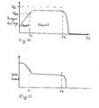
- the heater current and high voltage pulse change with time as shown in Figs. 7A and 7B respectively. (The onset of high voltage pulses is delayed at first because the initial low trigger voltage is not sufficient to set the NLDE in the positive polarity therefore no negative transition occurs.)
- a diode D 4 in Fig. 6 isolates the high negative pulse generated by the NLDE from the rest of the circuit.
- the repetition waveforms occurring as the trigger point reaches V BK are as shown in Fig. 7C.
- the dash, full and dotted lines show the mains supply voltage, voltage across the lamp or tube, and the cathode heater current respectively. With appropriate choice of components this can be arranged to be appropriate for starting a tube completely, provided the cathodes are sufficiently heated. A typical time of 0.3 seconds (t l ) to reach V BK is normally sufficient for this to happen. Should the heating not be sufficient because of adverse conditions, then the starter continues to be active giving the additional heating required.
- the firing angle now changes only slowly to give effective longer heating, but eventually times out completely if the tube fails to strike. This latter feature is necessary in order to prevent ballast overheating and annoying flashing, both of which can occur if a tube is faulty.
- PTC positive temperature coefficient resistor
- a PTC can be added to the circuits of Figs. 1, 2 and 6, for example, by breaking the circuit at terminal T 3 and inserting the PTC at that point.
- advantage can be taken of the inclusion of the PTC to replace the function of the second time constant in the dual rate circuits of Figs. 2 and 6.
- Fig. 9 shows a modified version of Fig. 2 in which the zener diode Z 2 and capacitor C 3 are omitted but further voltage clamping zener diode Z 4 is provided as shown to define a limit V BK to the bias voltage developed across C 1 . In this case the voltage is not allowed to rise to V s (see Fig.
- the rate of increase is very slow so that each successive cycle of applied mains results in only a very small charging current in C 1 to the extent that the voltage thereby caused at C 2 is less than the voltage of Z 1 , so the thyristor is not triggered.
- the PTC therefore cools completely (re-sets) without the starter triggering and it is not until the power is removed (either by switching off or removing the tube) that C 1 can discharge and allow the starter to operate next time power is applied.
- the PTC causes the circuit to remain inoperative for a period until at t 3 the PTC has cooled sufficiently to allow a fresh start operation to commence.
- circuit of Fig. 6 using the NLDE can be modified in the same manner as indicated in Fig. 9.
- V BK the value of V BK is assumed to be equal to the positive tube conduction voltage threshold so that a circuit having a given V BK will work with tubes of any lesser threshold characteristic.
Landscapes
- Circuit Arrangements For Discharge Lamps (AREA)
Applications Claiming Priority (2)
| Application Number | Priority Date | Filing Date | Title |
|---|---|---|---|
| GB8419546 | 1984-07-31 | ||
| GB848419546A GB8419546D0 (en) | 1984-07-31 | 1984-07-31 | Electronic starters for fluorescent lamps |
Publications (2)
| Publication Number | Publication Date |
|---|---|
| EP0170528A2 true EP0170528A2 (de) | 1986-02-05 |
| EP0170528A3 EP0170528A3 (de) | 1986-03-26 |
Family
ID=10564745
Family Applications (1)
| Application Number | Title | Priority Date | Filing Date |
|---|---|---|---|
| EP85305469A Withdrawn EP0170528A3 (de) | 1984-07-31 | 1985-07-31 | Elektronische Startschaltung für Entladungslampen |
Country Status (2)
| Country | Link |
|---|---|
| EP (1) | EP0170528A3 (de) |
| GB (1) | GB8419546D0 (de) |
Cited By (3)
| Publication number | Priority date | Publication date | Assignee | Title |
|---|---|---|---|---|
| GB2237923A (en) * | 1989-09-01 | 1991-05-15 | Eev Ltd | Transmission lines with non-linear dielectric |
| EP0520735A1 (de) * | 1991-06-27 | 1992-12-30 | Lighting Electronics Limited | Elektronische Zündschaltung für Leuchtstofflampen |
| WO1996008944A1 (en) * | 1994-09-14 | 1996-03-21 | Ho Sung Lee | Electronic starter in a fluorescent lamp apparatus |
Family Cites Families (2)
| Publication number | Priority date | Publication date | Assignee | Title |
|---|---|---|---|---|
| US3978368A (en) * | 1973-02-21 | 1976-08-31 | Hitachi, Ltd. | Discharge lamp control circuit |
| JPS58192293A (ja) * | 1982-05-06 | 1983-11-09 | 三菱電機株式会社 | 放電灯点灯装置 |
-
1984
- 1984-07-31 GB GB848419546A patent/GB8419546D0/en active Pending
-
1985
- 1985-07-31 EP EP85305469A patent/EP0170528A3/de not_active Withdrawn
Cited By (3)
| Publication number | Priority date | Publication date | Assignee | Title |
|---|---|---|---|---|
| GB2237923A (en) * | 1989-09-01 | 1991-05-15 | Eev Ltd | Transmission lines with non-linear dielectric |
| EP0520735A1 (de) * | 1991-06-27 | 1992-12-30 | Lighting Electronics Limited | Elektronische Zündschaltung für Leuchtstofflampen |
| WO1996008944A1 (en) * | 1994-09-14 | 1996-03-21 | Ho Sung Lee | Electronic starter in a fluorescent lamp apparatus |
Also Published As
| Publication number | Publication date |
|---|---|
| EP0170528A3 (de) | 1986-03-26 |
| GB8419546D0 (en) | 1984-09-05 |
Similar Documents
| Publication | Publication Date | Title |
|---|---|---|
| US4165475A (en) | Discharge lamp with starter circuit | |
| KR950013272B1 (ko) | 방전 램프 점등, 고온 재점등 및 작동회로 | |
| US5047694A (en) | Lamp starting circuit | |
| US4937501A (en) | Circuit arrangement for starting a high-pressure gas discharge lamp | |
| EP0333359B1 (de) | Anlaufschaltungen für Entladungslampen | |
| US4521825A (en) | Gas ignition circuits | |
| US4629944A (en) | Starter circuit for a fluorescent tube lamp | |
| EP0195248A2 (de) | Start- und Betriebseinrichtung für Hochintensitätsentladungslampen | |
| US5059870A (en) | Electronic solid state starter for fluorescent lamps | |
| US4959593A (en) | Two-lead igniter for HID lamps | |
| US4210850A (en) | Circuits for operating electric discharge lamps | |
| US4177403A (en) | Electronic starter for igniting a discharge lamp | |
| EP0170528A2 (de) | Elektronische Startschaltung für Entladungslampen | |
| US5572093A (en) | Regulation of hot restrike pulse intensity and repetition | |
| US4749909A (en) | Compact igniter for discharge lamps | |
| GB2201307A (en) | Electronic starter for discharge lamps | |
| US6153983A (en) | Full wave electronic starter | |
| WO2002032194A2 (en) | Circuit arrangement | |
| US4642521A (en) | Compact igniter for discharge lamps | |
| GB2234868A (en) | Simplified electronic starter for fluorescent lamps | |
| US4112334A (en) | Ignition system for extending the lifetime of gas filled electric lamps | |
| GB2202347A (en) | Current interruption operating circuit for a gaseous discharge lamp | |
| GB2185867A (en) | Circuit for starting hot restarting, and operating an HID lamp | |
| GB2173055A (en) | Circuit arrangement for starting discharge lamps | |
| US6972529B2 (en) | Switch mode power supply for a gas discharge lamp |
Legal Events
| Date | Code | Title | Description |
|---|---|---|---|
| PUAI | Public reference made under article 153(3) epc to a published international application that has entered the european phase |
Free format text: ORIGINAL CODE: 0009012 |
|
| AK | Designated contracting states |
Designated state(s): AT BE DE FR GB IT NL SE |
|
| PUAL | Search report despatched |
Free format text: ORIGINAL CODE: 0009013 |
|
| AK | Designated contracting states |
Kind code of ref document: A3 Designated state(s): AT BE DE FR GB IT NL SE |
|
| 17P | Request for examination filed |
Effective date: 19860830 |
|
| 17Q | First examination report despatched |
Effective date: 19880315 |
|
| STAA | Information on the status of an ep patent application or granted ep patent |
Free format text: STATUS: THE APPLICATION IS DEEMED TO BE WITHDRAWN |
|
| 18D | Application deemed to be withdrawn |
Effective date: 19880926 |