EP0170489B1 - Heizeinrichtung - Google Patents
Heizeinrichtung Download PDFInfo
- Publication number
- EP0170489B1 EP0170489B1 EP85305258A EP85305258A EP0170489B1 EP 0170489 B1 EP0170489 B1 EP 0170489B1 EP 85305258 A EP85305258 A EP 85305258A EP 85305258 A EP85305258 A EP 85305258A EP 0170489 B1 EP0170489 B1 EP 0170489B1
- Authority
- EP
- European Patent Office
- Prior art keywords
- inlet
- fluid
- electrodes
- plates
- outlet
- Prior art date
- Legal status (The legal status is an assumption and is not a legal conclusion. Google has not performed a legal analysis and makes no representation as to the accuracy of the status listed.)
- Expired - Lifetime
Links
- 238000010438 heat treatment Methods 0.000 title claims abstract description 15
- XLYOFNOQVPJJNP-UHFFFAOYSA-N water Substances O XLYOFNOQVPJJNP-UHFFFAOYSA-N 0.000 claims abstract description 27
- 239000012530 fluid Substances 0.000 claims description 20
- 230000001419 dependent effect Effects 0.000 claims 1
- 239000008236 heating water Substances 0.000 abstract 1
- 239000000463 material Substances 0.000 description 11
- 229920003023 plastic Polymers 0.000 description 9
- 239000004033 plastic Substances 0.000 description 9
- 229910001220 stainless steel Inorganic materials 0.000 description 5
- 239000010935 stainless steel Substances 0.000 description 5
- RYGMFSIKBFXOCR-UHFFFAOYSA-N Copper Chemical compound [Cu] RYGMFSIKBFXOCR-UHFFFAOYSA-N 0.000 description 3
- 229910052802 copper Inorganic materials 0.000 description 3
- 239000010949 copper Substances 0.000 description 3
- 230000004888 barrier function Effects 0.000 description 2
- 239000006260 foam Substances 0.000 description 2
- 238000004519 manufacturing process Methods 0.000 description 2
- 230000007935 neutral effect Effects 0.000 description 2
- 238000009825 accumulation Methods 0.000 description 1
- 230000002939 deleterious effect Effects 0.000 description 1
- 238000010612 desalination reaction Methods 0.000 description 1
- 230000000694 effects Effects 0.000 description 1
- 238000001914 filtration Methods 0.000 description 1
- 239000011810 insulating material Substances 0.000 description 1
- 238000005342 ion exchange Methods 0.000 description 1
- 238000012423 maintenance Methods 0.000 description 1
- 239000002184 metal Substances 0.000 description 1
- 229910052751 metal Inorganic materials 0.000 description 1
- 238000009991 scouring Methods 0.000 description 1
- 238000005406 washing Methods 0.000 description 1
Images
Classifications
-
- H—ELECTRICITY
- H05—ELECTRIC TECHNIQUES NOT OTHERWISE PROVIDED FOR
- H05B—ELECTRIC HEATING; ELECTRIC LIGHT SOURCES NOT OTHERWISE PROVIDED FOR; CIRCUIT ARRANGEMENTS FOR ELECTRIC LIGHT SOURCES, IN GENERAL
- H05B3/00—Ohmic-resistance heating
- H05B3/60—Heating arrangements wherein the heating current flows through granular powdered or fluid material, e.g. for salt-bath furnace, electrolytic heating
-
- F—MECHANICAL ENGINEERING; LIGHTING; HEATING; WEAPONS; BLASTING
- F24—HEATING; RANGES; VENTILATING
- F24H—FLUID HEATERS, e.g. WATER OR AIR HEATERS, HAVING HEAT-GENERATING MEANS, e.g. HEAT PUMPS, IN GENERAL
- F24H1/00—Water heaters, e.g. boilers, continuous-flow heaters or water-storage heaters
- F24H1/10—Continuous-flow heaters, i.e. heaters in which heat is generated only while the water is flowing, e.g. with direct contact of the water with the heating medium
- F24H1/101—Continuous-flow heaters, i.e. heaters in which heat is generated only while the water is flowing, e.g. with direct contact of the water with the heating medium using electric energy supply
- F24H1/106—Continuous-flow heaters, i.e. heaters in which heat is generated only while the water is flowing, e.g. with direct contact of the water with the heating medium using electric energy supply with electrodes
Definitions
- This invention relates to a device for heating fluids, and is particularly although not exclusively concerned with a water heating device.
- the primary object of the invention is to provide a device with which a relatively large rise in temperature of a body of fluid can be achieved in a short period of time in an efficient and convenient manner.
- a heating device for heating a fluid comprising a vessel with a fluid inlet and a fluid outlet, a plurality of closely-spaced electrode plates within the vessel extending parallel or substantially parallel to each other, said plates having holes therein and electrical terminals for connection to a source of electric power, alternate said electrodes being connected to different said terminals (as known for example from FR-A-517 541 characterised in that a plurality of wall structures are provided within said vessel defining a plurality of fluid passages which extend alongside each other and through the plates, said passages being interconnected in succession to each other to define a continuous passageway connected at opposite ends respectively to the said inlet and outlet so that fluid introduced into said inlet is constrained to flow along said passageway backwards and forwards along the passages in opposite directions through said plates to said outlet.
- tubes there may be multiple tubes disposed coaxially inside each other to define therebetween the said passages.
- These tubes may be formed from a suitable plastics material which is electrically insulating and capable of containing the heated fluid without undue deleterious effects.
- the electrodes may be formed from any suitable metal or other material having requisite thermal and electrical properties, and also adequate resistance to attack by the heated fluid.
- Stainless steel is a suitable material.
- the electrodes are preferably used with a.c. supply. Preferably there are more than two electrodes and these may be connected alternately to different phases or different polarities of the supply.
- the heating device of the invention may have particular application in the heating of water to produce hot water or steam for any suitable purpose and in any suitable context whether domestic, commercial or industrial.
- the heated fluid may be dispensed for use, e.g. for washing purposes, or may be used in connected equipment e.g. to heat a further fluid or other material or to operate steam-driven apparatus or for any other suitable purpose.
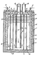
- the device comprises a stainless steel vessell having a cylindrical body 2 closed at its top and bottom ends respectively with a lid 3 and a bottom wall 4.
- the vessel 1 has an inner vessel or lining 5 of an insulating plastics material which covers the inner surfaces of the body 2 and the bottom wall 4.
- the undersurface of the lid 3 is covered with a layer 6 of this plastics material and a disc 7 of the same material is fixed below and parallel to this so as to define an outlet cavity 8 therebetween.
- the centre tube 9 is fixed at its top end around a central hole 12 in the disc 7 and a copper inlet tube 13 which extends upwardly through the lid 3 is bonded within this hole 12. At its bottom end this tube 9 terminates slightly above the bottom wall 4.
- the other tubes 10, 11 are fixed at their top and bottom ends to the disc 7 and the bottom of the lining 5.
- the tubes 9 to 11 are intersected at right angles throughout their length by multiple parallel circular discs 14, 15 which are fixed to the tubes 9-11 and, at their outer peripheries, extend up to the lining 5.
- the discs 14, 15 are perforated stainless steel plates one-sixteenth of an inch thick (1.6mm) and one-quarter of an inch apart (6.4mm).
- Each rod 16 is connected to a respective set of alternate discs 14, 15, the other discs 15 or 14 being cut away round the rod 16 to permit this.
- the rods 16 extend upwardly through the lid 3 and connect with electrical terminals 17.
- a short copper outlet tube 18 extends through the lid 3 into communication with the cavity 8 between the lid 3 and the disc 7.
- the inlet tube 13 is connected via piping to a water supply and the outlet tube 18 is connected via piping to a tap or other dispense outlet or apparatus where hot water is required.
- the terminals 17 are connected respectively to neutral and live wires of a.c. mains supply, and the body 2 of the vessel 1 is connected, if required, to earth.
- the a.c. supply is switched on and the water is caused to flow through the heating device from the inlet tube 13 to the outlet tube 18.
- the path of the water is down through the tube 9, up between the tubes 9, 10, through top side holes 19 in the tube 10, down between the tubes 10 and 11, through bottom side holes 20 in the tube 11, up between the tube 11 and the body 2, and through holes 21 in the disc 7 into the cavity 8.
- the water passes through the perforations in the discs 14, 15. It will be noted that the stainless steel vessel 1 is completely isolated from the water by the plastics lining 5 and the lid cover 6.
- the electric supply produces opposite potentials between each pair of adjacent discs 14 and 15 and this gives rise to dissipation of electrical energy conductively and capacitively between the electrodes 14, 15 through the water. Resistive heating of the water and of the discs 14, 15 is thereby effected and there is a constant interchange of such heat between the water and the discs 14, 15. The result of this is that the water is heated to a high temperature in a particularly efficient and effective manner. For example, it is possible to boil two litres of water from room temperature in less than 10 seconds without undue consumption of electric power.
- the device can be installed and provided with appropriate control circuitry in any suitable manner.
- the device may be incorporated in a domestic hot water system and arranged so that the electric supply is automatically switched on when the water flows.
- Temperature adjustment may be effected by adjusting water flow rate and/or electric supply voltage or current.
- the device is not restricted to use in the context of production of hot water - the device may also be used for producing steam or for any other suitable purpose.
- the body 2 and the lid 3 are preferably earthed to avoid generation of radio frequency signals which may cause interference with nearby radio or television equipment.
- a highly conductive earthed screen may be incorporated around the periphery of the device.
- a thermally insulating barrier layer 21 may be provided around the periphery of the device internally or externally of the body 2 (and possibly also the lid 3).
- This layer may comprise, as shown, an evacuated space. Alternatively or additionally a foam plastics material or the like may be used.
- thermally insulating barrier layer 22 which may also comprise an evacuated space and/or a foam plastics material or the like, around the periphery of the tube 9 to avoid undue dissipation of heat from the body of water flowing between the electrodes 14, 15 into the supplied cold water in the inlet tubes 13, 9.
- the conductive rods 16 may be insulated between the connections to the electrodes 14, 15 to ensure that the electrical heating effect is concentrated between the confronting surfaces of the electrodes.
- the lid 3 may be releasably fastened to the body 2 in any suitable manner so that access can be had to the interior of the device for maintenance purposes.
- the discs 14, 15 shown in the drawing may be sealed via insulating material relative to the rods and the cylindrical body 2 so that water circulates under pressure through the perforations in the discs thereby giving a scouring action preventing accumulation of any deposits on the discs.
- any suitable filtering or ion exchange arrangement or the like may be used in conjunction with the device.
- the discs 14, 15 will be connected to opposite polarities and the final disc through which the water passes before leaving the device will preferably be at neutral potential where a.c. mains is used.
- Heating control may be achieved, as described by adjusting flow rate.
- the voltage or frequency of the electrical supply may be adjusted, or the supply may be switched on and off with a thermostat.
- the tubes 9-11 may be plastics or may be earthed copper tubes which are plastics coated or otherwise insulated relative to the discs 14; 15.
- the device can be used for desalination purposes as well as for generating hot water and steam.
Landscapes
- Engineering & Computer Science (AREA)
- General Engineering & Computer Science (AREA)
- Chemical & Material Sciences (AREA)
- Thermal Sciences (AREA)
- Combustion & Propulsion (AREA)
- Mechanical Engineering (AREA)
- Physics & Mathematics (AREA)
- Inorganic Insulating Materials (AREA)
- Mounting, Exchange, And Manufacturing Of Dies (AREA)
- Basic Packing Technique (AREA)
- Instantaneous Water Boilers, Portable Hot-Water Supply Apparatuses, And Control Of Portable Hot-Water Supply Apparatuses (AREA)
- Resistance Heating (AREA)
- Yarns And Mechanical Finishing Of Yarns Or Ropes (AREA)
- Baking, Grill, Roasting (AREA)
- Cookers (AREA)
Claims (5)
dadurch gekennzeichnet, daß innerhalb des Behälters mehrere Wände (9, 10, 11) vorgesehen sind, die eine Mehrzahl von Flüssigkeitskanälen definieren, die sich längs nebeneinander erstrekken und die platten durchsetzen, und die aufeinanderfolgend miteinander verbunden sind, so daß sie einen ununterbrochenen-Durchflußkanal bilden, der an seinen einander gegenüberliegenden Enden mit dem Einlaß (13) bzw. dem Auslaß (18) verbunden ist, so daß dem Einlaß zugeführte Flüssigkeit zwangsläufig durch den Durchflußkanal in gegenläufigen Richtungen rückwärts und vorwärts entlang den Kanälen und durch die Platten (14, 15) hindurch zu dem Auslaß strömt.
dadurch gekennzeichnet, daß die Wände (9, 10, 11) Bestandteil mehrerer koaxial angeordneter Rohre sind.
dadurch gekennzeichnet, daß die Elektroden und die Wände innerhalb eines zylindrischen Behälters (1) angeordnet sind.
dadurch gekennzeichnet, daß die Rohre (9, 10, 11) koaxial innerhalb des Behälters (1) angeordnet sind und die Platten (14, 15) kreisrunde Scheiben sind, die sich rechtwinklig zu den Rohren erstrekken.
dadurch gekennzeichnet, daß der Einlaß (13) an eine Wasserzuleitung angeschlossen ist und die Elektroden (14, 15) mit einer Wechselstromquelle über eine Steuerschaltung verbunden sind, wodurch die Wechselstromquelle eingeschaltet wird, wenn der Durchfluß von Wasser vom Einlaß zum Auslaß ausgelöst wird.
Priority Applications (1)
| Application Number | Priority Date | Filing Date | Title |
|---|---|---|---|
| AT85305258T ATE59458T1 (de) | 1984-08-01 | 1985-07-24 | Heizeinrichtung. |
Applications Claiming Priority (2)
| Application Number | Priority Date | Filing Date | Title |
|---|---|---|---|
| GB848419987A GB8419987D0 (en) | 1984-08-01 | 1984-08-01 | Heating devices |
| GB8419987 | 1984-08-01 |
Publications (3)
| Publication Number | Publication Date |
|---|---|
| EP0170489A2 EP0170489A2 (de) | 1986-02-05 |
| EP0170489A3 EP0170489A3 (en) | 1987-06-24 |
| EP0170489B1 true EP0170489B1 (de) | 1990-12-27 |
Family
ID=10564981
Family Applications (1)
| Application Number | Title | Priority Date | Filing Date |
|---|---|---|---|
| EP85305258A Expired - Lifetime EP0170489B1 (de) | 1984-08-01 | 1985-07-24 | Heizeinrichtung |
Country Status (6)
| Country | Link |
|---|---|
| US (1) | US4730098A (de) |
| EP (1) | EP0170489B1 (de) |
| AT (1) | ATE59458T1 (de) |
| AU (1) | AU589388B2 (de) |
| DE (1) | DE3581132D1 (de) |
| GB (1) | GB8419987D0 (de) |
Families Citing this family (22)
| Publication number | Priority date | Publication date | Assignee | Title |
|---|---|---|---|---|
| KR100445713B1 (ko) * | 1996-09-09 | 2004-10-14 | 니찌아스 카부시키카이샤 | 유체 가열 장치 |
| EP0857914A3 (de) * | 1997-02-05 | 1999-06-23 | Denel (Proprietary) Limited, Eloptro Division | Dampferzeuger |
| IL121527A0 (en) | 1997-08-12 | 1998-02-08 | U E T Ltd | Heating systems based on alternating-current electrodes |
| RU2121245C1 (ru) * | 1998-01-06 | 1998-10-27 | Анатолий Валентинович Ларев | Электронагреватель саморегулируемый |
| US6130990A (en) * | 1998-08-25 | 2000-10-10 | Nestec S.A. | On-demand direct electrical resistance heating system and method thereof |
| US6640048B2 (en) * | 2002-03-26 | 2003-10-28 | Don Novotny | Instant water heater |
| KR100517681B1 (ko) * | 2002-11-07 | 2005-09-28 | (주)천국 | 전기가열기 |
| CN100398900C (zh) * | 2005-04-30 | 2008-07-02 | 中国科学院等离子体物理研究所 | 基于多层管道结构获得高温热流体的方法 |
| US7817906B2 (en) * | 2005-05-04 | 2010-10-19 | Isi Technology, Llc | Direct electric resistance liquid heater |
| JP2006322683A (ja) * | 2005-05-20 | 2006-11-30 | Mitsubishi Heavy Ind Ltd | 蒸気発生器 |
| AU2009214821B2 (en) * | 2008-02-11 | 2012-12-13 | Microheat Technologies Pty Ltd | Segmented rapid heating of fluid |
| EP2603735A2 (de) * | 2010-08-09 | 2013-06-19 | Aldozkar D' Herrera Naranjo | Vorrichtung zur flüssigkeitserhitzung und dampferzeugung |
| BR112013005715B1 (pt) * | 2010-09-10 | 2020-10-06 | Heatworks Technologies, Inc | Dispositivo de manipulação de fluido, e, aquecedor de fluido |
| WO2012101470A1 (en) * | 2011-01-27 | 2012-08-02 | Universite Montpellier 2 - Sciences Et Techniques | Continuous heat treatment method and heating device for an electrically conductive fluid |
| CN103759406B (zh) * | 2014-01-24 | 2016-08-31 | 陈国良 | 单罐双管体双向电加热装置及空气能即热式热水器 |
| CN104121698A (zh) * | 2014-07-03 | 2014-10-29 | 孙冬梅 | 一种热水器恒流式电磁辅助加热装置 |
| US20170030577A1 (en) * | 2015-07-27 | 2017-02-02 | John Edward Vandigriff | Steam generation device and system |
| US20190003748A1 (en) * | 2015-12-21 | 2019-01-03 | United Technologies Corporation | Electrocaloric heat transfer system |
| WO2017125771A1 (en) | 2016-01-19 | 2017-07-27 | Dániel FATUSKA | Electric water heater |
| US11493233B2 (en) | 2016-09-26 | 2022-11-08 | Stone Aerospace, Inc. | Direct high voltage water heater |
| US11353241B2 (en) | 2016-11-07 | 2022-06-07 | Heatworks Technologies, Inc. | Devices for ohmically heating a fluid |
| US12467658B2 (en) | 2020-11-12 | 2025-11-11 | A. O. Smith Corporation | Diffuser for thermal storage tank |
Family Cites Families (13)
| Publication number | Priority date | Publication date | Assignee | Title |
|---|---|---|---|---|
| US991877A (en) * | 1910-01-13 | 1911-05-09 | Central Mfg Company | Electrical liquid-heater. |
| US1273451A (en) * | 1916-12-13 | 1918-07-23 | Manuel Bouzo | Electric heating apparatus. |
| FR517541A (fr) * | 1920-06-21 | 1921-05-07 | Louis Joseph Schneider | Appareil à eau chaude pour usages domestiques à réglage électrique |
| US1386607A (en) * | 1920-10-04 | 1921-08-09 | Raignau Adrien Frappier De | Electric water-heater |
| US1480515A (en) * | 1921-02-18 | 1924-01-08 | Caselli Ersilia | Electrical instantaneous water heater with continuous circulation, working at different voltages |
| US1491584A (en) * | 1922-04-04 | 1924-04-22 | Connor Walter | Air-cooled internal-combustion motor |
| GB574909A (en) * | 1943-07-24 | 1946-01-25 | Arthur Norman Jackson | Improvements in or relating to, electric heaters for liquids |
| US2380132A (en) * | 1943-12-18 | 1945-07-10 | James N Schien | Instant heater for liquids |
| US2444508A (en) * | 1945-10-29 | 1948-07-06 | Paul P Horni | Electric heater for flowing fluid |
| US2481958A (en) * | 1948-04-09 | 1949-09-13 | Videche Carlos | Fluid heater |
| GB850744A (en) * | 1958-03-10 | 1960-10-05 | Sydney Thompson | Improvements in or relating to electrical water heaters |
| US3005083A (en) * | 1958-10-29 | 1961-10-17 | Lorenzo E Mendoza | Electro-heater |
| GB1560782A (en) * | 1977-01-14 | 1980-02-13 | Williams S | Water heater |
-
1984
- 1984-08-01 GB GB848419987A patent/GB8419987D0/en active Pending
-
1985
- 1985-07-24 AT AT85305258T patent/ATE59458T1/de not_active IP Right Cessation
- 1985-07-24 DE DE8585305258T patent/DE3581132D1/de not_active Expired - Lifetime
- 1985-07-24 EP EP85305258A patent/EP0170489B1/de not_active Expired - Lifetime
- 1985-07-30 US US06/760,660 patent/US4730098A/en not_active Expired - Fee Related
- 1985-12-24 AU AU51620/85A patent/AU589388B2/en not_active Ceased
Also Published As
| Publication number | Publication date |
|---|---|
| DE3581132D1 (de) | 1991-02-07 |
| US4730098A (en) | 1988-03-08 |
| ATE59458T1 (de) | 1991-01-15 |
| AU589388B2 (en) | 1989-10-12 |
| EP0170489A2 (de) | 1986-02-05 |
| EP0170489A3 (en) | 1987-06-24 |
| GB8419987D0 (en) | 1984-09-12 |
| AU5162085A (en) | 1987-06-25 |
Similar Documents
| Publication | Publication Date | Title |
|---|---|---|
| EP0170489B1 (de) | Heizeinrichtung | |
| GB2164732A (en) | Heating water | |
| CA1224836A (en) | Multiple temperature autoregulating heater | |
| US3796857A (en) | Electrode boiler | |
| US1727585A (en) | Fluid heating and vaporizing apparatus | |
| JPH06208887A (ja) | 電磁誘導加熱蒸気発生器 | |
| JP2020516046A (ja) | 流体の通電加熱のシステム及び方法 | |
| CA1266075A (en) | Heating devices | |
| RU2030126C1 (ru) | Электродный нагреватель жидкости "мечта 4" | |
| RU2074529C1 (ru) | Индукционной нагреватель жидкости | |
| US10281138B2 (en) | Electrode water heater | |
| KR101623545B1 (ko) | 난방용 전열관 | |
| US2324837A (en) | Electric heater | |
| KR19990054160A (ko) | 이온운동에너지를 이용한 유체가열방식의 전기보일러 | |
| RU2042081C1 (ru) | Электроводонагреватель малой мощности | |
| SU1728574A1 (ru) | Электрический котел | |
| RU2096930C1 (ru) | Прямоточный электронагреватель жидкости | |
| US1827639A (en) | Heater | |
| RU2059166C1 (ru) | Электродный нагреватель | |
| RU2059165C1 (ru) | Способ нагрева воды и электроводонагреватель (варианты) | |
| RU2095717C1 (ru) | Тепловая труба | |
| US1002637A (en) | Water-heating apparatus. | |
| RU1827058C (ru) | "Универсальный электронагреватель жидкости "Мечта-3" | |
| RU2557141C1 (ru) | Способ и устройство получения тепловой энергии из электрической | |
| US1139001A (en) | Electrical water-heater. |
Legal Events
| Date | Code | Title | Description |
|---|---|---|---|
| PUAI | Public reference made under article 153(3) epc to a published international application that has entered the european phase |
Free format text: ORIGINAL CODE: 0009012 |
|
| AK | Designated contracting states |
Designated state(s): AT BE CH DE FR IT LI LU NL SE |
|
| PUAL | Search report despatched |
Free format text: ORIGINAL CODE: 0009013 |
|
| RHK1 | Main classification (correction) |
Ipc: F24H 1/10 |
|
| AK | Designated contracting states |
Kind code of ref document: A3 Designated state(s): AT BE CH DE FR IT LI LU NL SE |
|
| 17P | Request for examination filed |
Effective date: 19880222 |
|
| 17Q | First examination report despatched |
Effective date: 19890904 |
|
| GRAA | (expected) grant |
Free format text: ORIGINAL CODE: 0009210 |
|
| AK | Designated contracting states |
Kind code of ref document: B1 Designated state(s): AT BE CH DE FR IT LI LU NL SE |
|
| PG25 | Lapsed in a contracting state [announced via postgrant information from national office to epo] |
Ref country code: SE Free format text: THE PATENT HAS BEEN ANNULLED BY A DECISION OF A NATIONAL AUTHORITY Effective date: 19901227 Ref country code: NL Effective date: 19901227 Ref country code: LI Effective date: 19901227 Ref country code: IT Free format text: LAPSE BECAUSE OF FAILURE TO SUBMIT A TRANSLATION OF THE DESCRIPTION OR TO PAY THE FEE WITHIN THE PRESCRIBED TIME-LIMIT;WARNING: LAPSES OF ITALIAN PATENTS WITH EFFECTIVE DATE BEFORE 2007 MAY HAVE OCCURRED AT ANY TIME BEFORE 2007. THE CORRECT EFFECTIVE DATE MAY BE DIFFERENT FROM THE ONE RECORDED. Effective date: 19901227 Ref country code: FR Effective date: 19901227 Ref country code: CH Effective date: 19901227 Ref country code: BE Effective date: 19901227 Ref country code: AT Effective date: 19901227 |
|
| REF | Corresponds to: |
Ref document number: 59458 Country of ref document: AT Date of ref document: 19910115 Kind code of ref document: T |
|
| REF | Corresponds to: |
Ref document number: 3581132 Country of ref document: DE Date of ref document: 19910207 |
|
| REG | Reference to a national code |
Ref country code: CH Ref legal event code: PL |
|
| NLV1 | Nl: lapsed or annulled due to failure to fulfill the requirements of art. 29p and 29m of the patents act | ||
| EN | Fr: translation not filed | ||
| PG25 | Lapsed in a contracting state [announced via postgrant information from national office to epo] |
Ref country code: LU Free format text: LAPSE BECAUSE OF NON-PAYMENT OF DUE FEES Effective date: 19910731 |
|
| PLBE | No opposition filed within time limit |
Free format text: ORIGINAL CODE: 0009261 |
|
| STAA | Information on the status of an ep patent application or granted ep patent |
Free format text: STATUS: NO OPPOSITION FILED WITHIN TIME LIMIT |
|
| 26N | No opposition filed | ||
| PG25 | Lapsed in a contracting state [announced via postgrant information from national office to epo] |
Ref country code: DE Effective date: 19920401 |