EP0170085B1 - Safety rim with an axial bead-retaining hump, and a tyre-and-wheel assembly using said rim - Google Patents
Safety rim with an axial bead-retaining hump, and a tyre-and-wheel assembly using said rim Download PDFInfo
- Publication number
- EP0170085B1 EP0170085B1 EP85108224A EP85108224A EP0170085B1 EP 0170085 B1 EP0170085 B1 EP 0170085B1 EP 85108224 A EP85108224 A EP 85108224A EP 85108224 A EP85108224 A EP 85108224A EP 0170085 B1 EP0170085 B1 EP 0170085B1
- Authority
- EP
- European Patent Office
- Prior art keywords
- rim
- fact
- hump
- bead seat
- groove
- Prior art date
- Legal status (The legal status is an assumption and is not a legal conclusion. Google has not performed a legal analysis and makes no representation as to the accuracy of the status listed.)
- Expired
Links
Images


Classifications
-
- B—PERFORMING OPERATIONS; TRANSPORTING
- B60—VEHICLES IN GENERAL
- B60C—VEHICLE TYRES; TYRE INFLATION; TYRE CHANGING; CONNECTING VALVES TO INFLATABLE ELASTIC BODIES IN GENERAL; DEVICES OR ARRANGEMENTS RELATED TO TYRES
- B60C15/00—Tyre beads, e.g. ply turn-up or overlap
- B60C15/02—Seating or securing beads on rims
- B60C15/0236—Asymmetric bead seats, e.g. different bead diameter or inclination angle
-
- B—PERFORMING OPERATIONS; TRANSPORTING
- B60—VEHICLES IN GENERAL
- B60B—VEHICLE WHEELS; CASTORS; AXLES FOR WHEELS OR CASTORS; INCREASING WHEEL ADHESION
- B60B21/00—Rims
- B60B21/10—Rims characterised by the form of tyre-seat or flange, e.g. corrugated
Definitions
- the present invention relates to rims, in one piece for tire casings, more particularly to those whose profile is of shape designed to retain the bead on its seat. It also relates to pneumatic assemblies consisting of a tire casing mounted on a rim.
- a single-piece rim must have a central circumferential groove to allow the mounting of the casing, and two seats on which, under the effect of the inflation pressure, are placed and wedged the beads of the envelope.
- Each seat is extended externally by a rim flange.
- bosses forming a stop, commonly designated by "hump".
- the use of such bosses has also been generalized for passenger car tire assemblies without inner tubes. These bosses are of standardized shapes (see for example the standards of the E.T.R.T.O.).
- Patent application FR-A-2 528 362 proposes, in order to combat loosening, a boss of particular shape, asymmetrical.
- the radial height of said boss varies between a minimum and a maximum along the circumferential development of said boss and this in at least two distinct planes perpendicular to the axis of rotation.
- the purpose of this application is to have, in each meridian plane, a boss of height increased compared to the bosses of the type described above, without excessively increasing the circumferential development of said boss, considered in a plane perpendicular to the axis of rotation.
- a bead is relatively rigid due to the presence of at least one rod, sometimes of cable or rubber reinforcements with high elasticity modulus. This rigidity is necessary to secure the casing with the rim. This rigidity thwarts and limits the radial extension of the base of the bead and, consequently, it limits the height of the boss which allows easy mounting of the envelope. The full efficiency of the bosses is compromised.
- the problem underlying the invention consisted in finding the means of using a boss of great radial height, allowing an effective retention of the bead on its seat, while ensuring an easy mounting of this bead under the sole effect of the inflation pressure.
- the rim according to the invention having a central circumferential groove, comprising two bead seats, each seat being extended on the axially outer side by a flange and on the axially inner side by a boss, is remarkable in that, on one side at less than the central circumferential throat,
- auxiliary bead seat located axially between said central circumferential groove and said boss, radially between said groove and the top of said boss, said auxiliary seat developing circumferentially at least on an arc of 30 °,
- connection surface between said top of said boss and the side of said groove, on the side diametrically opposite to said auxiliary seat, is inclined towards said groove, said inclined surface extending circumferentially at least over an arc of 120 °.
- the bead when, after having introduced the beads into the mounting groove in the usual way, the tire is subjected to the inflation pressure, the bead finds a point of temporary equilibrium by engaging on said auxiliary seat, which cancels its natural tendency to want to cross the boss circumferentially everywhere at the same time. Such crossing is impossible when the boss has a large radial height. Under the effect of the inflation pressure, it first crosses the boss at the place diametrically opposite to said auxiliary seat, that is to say at the place where an inclined connection surface has been arranged, and positions himself on his seat. The rest of the boss is gradually passed. Thus, a high boss can be crossed alternately.
- the invention is independent of the bead seat itself.
- the invention allows the use of a boss forming a stop of high height and circumferentially regular along the axially inner edge of the bead seat.
- circumferentially regular height stop is meant a stop which is only circumferentially interrupted for a short length, of the order of a few centimeters, to facilitate the disassembly by pushing the bead towards the central groove at the level of a place where the boss is interrupted.
- the auxiliary seat is situated radially at a circumferentially variable level, starting from a maximum, gradually decreasing towards a minimum, then, symmetrically, rising to the same maximum.
- said auxiliary seat extends over an arc of at least 120 °.
- the rim has two bead seats (1) each extended externally by a flange (2), and a central circumferential groove (3) intended to allow the mounting of the beads.
- Each bead seat is extended axially inwards by a boss (4) forming a stop for axially retaining the bead on its seat (1).
- the height H of said boss (4) relative to the seat (1) is preferably greater than or equal to 3 mm.
- the rim On each side of the groove (3), the rim has an auxiliary seat (5) located axially between the mounting groove (3) and the boss (4) retaining the bead.
- This auxiliary seat appears clearly in FIGS. 1, 3 and 4.
- said auxiliary seat has a bearing surface (50) located radially at a level which varies circumferentially from a maximum "M" at the azimuth of the section CC, gradually decreases towards a minimum "m" at the azimuth of section BB to increase again, symmetrically towards the same maximum.
- Said auxiliary seat extends circumferentially over an arc of 150 °.
- the values of said maximum and of said minimum must be achieved in such a way that the circumferential development measured at the surface of the rim, in a plane passing through the auxiliary mounting seat at the azimuth of the section BB and by the top of the boss at the azimuth of the section is equal, as a first approximation, to the circumferential development measured under the bead of the tire covering intended to be mounted on the rim.
- connection surface inclined towards said groove is situated on the side diametrically opposite to said auxiliary seat (5); the description of the mounting of a bead which will follow clearly shows the role.
- FIG. 2 there are shown two alternative embodiments.
- said connection surface between the top (40) of said boss (4) and the flank (30) of the groove (3) consists of a substantially conical surface (41) extending circumferentially son a 150 ° arc. This substantially conical face (41) also appears in FIG. 1.
- said connection surface between the top (40) of said boss (4) and the side (30) of the groove (3) is constituted by a partial toric surface (42).
- FIG. 6 shows a bead (7) provided with a rod (70). Under the effect of the inflation pressure, the bead is positioned on the auxiliary seat (5). As the inflation pressure increases, the bead (7) slides along the substantially conical face (41), then crosses the top (40) of the boss (4) diametrically opposite the auxiliary seat (5) ( see figure 7). By the fact that the crossing is thus initiated, the bead spontaneously continues this crossing on either side of the initial place.
- the auxiliary seat (5) At the end of this movement, it permanently leaves the auxiliary seat (5) - see Figure 8-.
- the role of the partial toric surface (42) is identical to that of the substantially conical surface (41). More generally, it involves drawing a connection surface inclined towards the groove (3) such that it has less resistance to the axial displacement of the bead (7) under the effect of the inflation pressure than the resistance to displacement axial of the bead (7) presented by the auxiliary seat (5). Thanks to the rim profile according to the invention, which provides a zone where the bead finds a temporary equilibrium - the auxiliary seat (5), the deformation of the bead necessary for it to cross a stop of given external diameter is minimized by organizing an alternate crossing.
- the boss (4) can be interrupted for a few centimeters: the disassembly tools (levers, etc.) are used to push back the bead (7) of the tire casing at the right of an interruption ( 6) clearly visible in Figures 1 and 5; the bead is again pushed into another place close to the first; he then crosses the boss, falls into the central groove (3) and the final disassembly is done in a conventional manner.
- the disassembly tools (levers, etc.) are used to push back the bead (7) of the tire casing at the right of an interruption ( 6) clearly visible in Figures 1 and 5; the bead is again pushed into another place close to the first; he then crosses the boss, falls into the central groove (3) and the final disassembly is done in a conventional manner.
- the invention makes it possible to produce non-removable assemblies.
- the boss (4) is then circumferentially continuous - no interruption (6) - and the radial height of said boss (4) must be sufficiently large, which can very easily be determined experimentally.
Abstract
Description
La présente invention se rapporte aux jantes, en une seule pièce pour enveloppes de pneumatiques, plus particulièrement à celles dont le profil est de forme étudiée pour retenir le bourrelet sur son siège. Elle concerne également les ensembles pneumatiques constitués d'une enveloppe de pneumatique montée sur une jante.The present invention relates to rims, in one piece for tire casings, more particularly to those whose profile is of shape designed to retain the bead on its seat. It also relates to pneumatic assemblies consisting of a tire casing mounted on a rim.
Comme on le sait, une jante en une seule pièce comporte obligatoirement une gorge circonférentielle centrale pour permettre le montage de l'enveloppe, et deux sièges sur lesquels, sous l'effet de la pression de gonflage, viennent se placer et se coincer les bourrelets de l'enveloppe. Chaque siège est prolongé extérieurement par un rebord de jante.As we know, a single-piece rim must have a central circumferential groove to allow the mounting of the casing, and two seats on which, under the effect of the inflation pressure, are placed and wedged the beads of the envelope. Each seat is extended externally by a rim flange.
Lorsqu'est appliqué à l'enveloppe de pneumatique un effort transversal important, par exemple dû à la force centrifuge lors d'un virage pris à grande allure, il peut se produire un décoincement : un bourrelet (du côté extérieur au virage) quitte son siège, se trouve repoussé axialement vers l'intérieur de jante pendant son passage entre la route et la jante parce que la force transversale de réaction à la force centrifuge n'est pas compensée par la force résultant de la pression de gonflage. Le bourrelet risque de séloigner axialement de son siège de manière telle qu'il puisse tomber dans la gorge circonférentielle de montage. Il s'ensuit presque toujours une perte de pression et une perte du pouvoir directeur du pneumatique.When a significant transverse force is applied to the tire, for example due to the centrifugal force during a bend taken at high speed, there can be a loosening: a bead (on the side outside the bend) leaves its seat, is pushed axially towards the inside of the rim during its passage between the road and the rim because the transverse force of reaction to the centrifugal force is not compensated by the force resulting from the inflation pressure. The bead risks moving away axially from its seat so that it can fall into the circumferential mounting groove. This almost always results in a loss of pressure and a loss of the steering power of the tire.
On connaît divers moyens visant à améliorer la résistance au décoincement par le choix d'une forme appropriée du profil de la jante. Un de ces moyens consiste à retenir le bourrelet du côté intérieur de la jante par un bossage formant butée, communément désigné par "hump". L'usage de pareils bossages s'est d'ailleurs généralisé pour les ensembles pneumatiques de tourisme montés sans chambre à air. Ces bossages sont de formes normalisées (voir par exemple les normes de l'E.T.R.T.O.).Various means are known for improving the resistance to loosening by choosing an appropriate shape of the rim profile. One of these means consists in retaining the bead on the inner side of the rim by a boss forming a stop, commonly designated by "hump". The use of such bosses has also been generalized for passenger car tire assemblies without inner tubes. These bosses are of standardized shapes (see for example the standards of the E.T.R.T.O.).
La demande de brevet FR-A-2 528 362 propose, pour lutter contre le décoincement, un bossage de forme particulière, asymétrique. La hauteur radiale dudit bossage varie entre un minimum et un maximum le long du développement circonférentiel dudit bossage et ce dans au moins deux plans distincts perpendiculaires à l'axe de rotation. Le but poursuivi par cette demande est de disposer, dans chaque plan méridien, un bossage de hauteur agrandie par rapport aux bossages du type précédemment décrit, sans trop augmenter le développement circonférentiel dudit bossage, considéré dans un plan perpendiculaire à l'axe de rotation.Patent application FR-A-2 528 362 proposes, in order to combat loosening, a boss of particular shape, asymmetrical. The radial height of said boss varies between a minimum and a maximum along the circumferential development of said boss and this in at least two distinct planes perpendicular to the axis of rotation. The purpose of this application is to have, in each meridian plane, a boss of height increased compared to the bosses of the type described above, without excessively increasing the circumferential development of said boss, considered in a plane perpendicular to the axis of rotation.
L'efficacité des bossages connus, quoique parfois appréciable, se révèle insuffisante pour maintenir les bourrelets sur leurs sièges dans certaines conditions de roulage. En outre, avec les bossages connus, on rencontre vite des difficultés de montage importantes lorsque l'on cherche à en améliorer l'efficacité en élevant radialement le sommet desdits bossages. En effet, un bourrelet est relativement rigide du fait de la présence d'au moins une tringle, parfois de renforts câbles ou en gomme à haut module d'élasticité. Cette rigidité est nécessaire pour solidariser l'enveloppe avec la jante. Cette rigidité contrarie et limite l'extension radiale de la base du bourrelet et, partant, elle limite la hauteur du bossage qui permette un montage aisé de l'enveloppe. La pleine efficacité des bossages s'en trouve compromise.The effectiveness of known bosses, although sometimes appreciable, is insufficient to keep the beads on their seats under certain driving conditions. In addition, with known bosses, one quickly encounters significant mounting difficulties when one seeks to improve the efficiency by radially raising the top of said bosses. Indeed, a bead is relatively rigid due to the presence of at least one rod, sometimes of cable or rubber reinforcements with high elasticity modulus. This rigidity is necessary to secure the casing with the rim. This rigidity thwarts and limits the radial extension of the base of the bead and, consequently, it limits the height of the boss which allows easy mounting of the envelope. The full efficiency of the bosses is compromised.
Le problème à la base de l'invention a consisté à rechercher le moyen d'utiliser un bossage de grande hauteur radiale, permettant une retenue efficace du bourrelet sur son siège, tout en assurant un montage aisé de ce bourrelet sous le seul effet de la pression de gonflage.The problem underlying the invention consisted in finding the means of using a boss of great radial height, allowing an effective retention of the bead on its seat, while ensuring an easy mounting of this bead under the sole effect of the inflation pressure.
La jante selon l'invention, possédant une gorge circonférentielle centrale, comportant deux sièges de bourrelet, chaque siège étant prolongé du côté axialement extérieur par un rebord et du côté axialement intérieur par un bossage, est remarquable en ce que, d'un côté au moins de la gorge circonférentialle centrale,The rim according to the invention, having a central circumferential groove, comprising two bead seats, each seat being extended on the axially outer side by a flange and on the axially inner side by a boss, is remarkable in that, on one side at less than the central circumferential throat,
a) elle comporte un siège auxiliaire de bourrelet, situé axialement entre ladite gorge circonférentielle centrale et ledit bossage, radialement entre ladite gorge et le sommet dudit bossage, ledit siège auxiliaire se développant circonférentiellement au moins sur un arc de 30° ,a) it comprises an auxiliary bead seat, located axially between said central circumferential groove and said boss, radially between said groove and the top of said boss, said auxiliary seat developing circumferentially at least on an arc of 30 °,
b) la surface de raccordement entre ledit sommet dudit bossage et le flanc de ladite gorge, du côté diamétralement opposé audit siège auxiliaire, est inclinée vers ladite gorge, ladite surface inclinée s'étendant circonférentiellement au moins sur un arc de 120°.b) the connection surface between said top of said boss and the side of said groove, on the side diametrically opposite to said auxiliary seat, is inclined towards said groove, said inclined surface extending circumferentially at least over an arc of 120 °.
Grâce au siège auxiliaire de la jante selon l'invention, lorsque, après avoir introduit les bourrelets dans la gorge de montage de manière usuelle, on soumet l'enveloppe de pneumatique à la pression de gonflage, le bourrelet trouve un point d'équilibre provisoire en s'engageant sur ledit siège auxiliaire, ce qui annule sa tendance naturelle à vouloir franchir le bossage circonférentiellement partout en même temps. Un tel franchissement est impossible lorsque le bossage présente une grande hauteur radiale. Sous l'effet de la pression de gonflage, il franchit le bossage d'abord à l'endroit diamétralement opposé audit siège auxiliaire, c'est-à-dire à l'endroit où l'on a aménagé une surface de raccordement inclinée, et se positionne sur son siège. Le reste du bossage est franchi progressivement. Ainsi, un bossage de grande hauteur peut être franchi de manière alternée.Thanks to the auxiliary seat of the rim according to the invention, when, after having introduced the beads into the mounting groove in the usual way, the tire is subjected to the inflation pressure, the bead finds a point of temporary equilibrium by engaging on said auxiliary seat, which cancels its natural tendency to want to cross the boss circumferentially everywhere at the same time. Such crossing is impossible when the boss has a large radial height. Under the effect of the inflation pressure, it first crosses the boss at the place diametrically opposite to said auxiliary seat, that is to say at the place where an inclined connection surface has been arranged, and positions himself on his seat. The rest of the boss is gradually passed. Thus, a high boss can be crossed alternately.
L'invention est indépendante du siège de bourrelet proprement dit. L'invention permet d'utiliser un bossage formant une butée de hauteur élevée et circonférentiellement régulière le long du bord axialement intérieur du siège de bourrelet. Par "butée de hauteur circonférentiellement régulière", on entend une butée qui n'est interrompue circonférentiellement que pendant une faible longueur, de l'ordre de quelques centimètres, pour faciliter le démontage en repoussant le bourrelet vers la gorge centrale à hauteur d'un endroit où le bossage est interrompu.The invention is independent of the bead seat itself. The invention allows the use of a boss forming a stop of high height and circumferentially regular along the axially inner edge of the bead seat. By "circumferentially regular height stop" is meant a stop which is only circumferentially interrupted for a short length, of the order of a few centimeters, to facilitate the disassembly by pushing the bead towards the central groove at the level of a place where the boss is interrupted.
De manière avantageuse, la siège auxiliaire se situe radialement à un niveau circonférentiellement variable, partant d'un maximum, diminuant progressivement vers un minimum, puis, de manière symétrique, s'élevant jusqu'au même maximum.Advantageously, the auxiliary seat is situated radially at a circumferentially variable level, starting from a maximum, gradually decreasing towards a minimum, then, symmetrically, rising to the same maximum.
De manière avantageuse, ladit siège auxiliaire s'étend sur un arc d'au moins 120°.Advantageously, said auxiliary seat extends over an arc of at least 120 °.
L'invention va être mieux comprise en consultant la description suivante et les dessins s'y rapportant, donnés uniquement à titre d'exemple et de manière non limitative.The invention will be better understood by consulting the following description and the drawings relating thereto, given solely by way of example and without limitation.
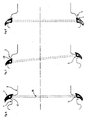
- La figure 1 est une coupe d'une jante selon l'invention suivant un plan perpendiculaire à l'axe de rotation passant par la gorge circonférentielle centrale.Figure 1 is a section of a rim according to the invention along a plane perpendicular to the axis of rotation passing through the central circumferential groove.
- La figure 2 est une coupe suivant AA à la figure 1.Figure 2 is a section along AA in Figure 1.
- La figure 3 est une coupe suivant BB à la figure 1.FIG. 3 is a section along BB in FIG. 1.
- La figure 4 est une coupe suivant CC à la figure 1.FIG. 4 is a section along CC in FIG. 1.
- La figure 5 est une coupe suivant DD à la figure 1.FIG. 5 is a section along DD in FIG. 1.
- La figure 6 est une coupe méridienne suivant AB à la figure 1, comportant en plus un bourrelet en début de montage.Figure 6 is a meridian section along AB in Figure 1, further comprising a bead at the start of assembly.
- La figure 7 représente le bourrelet en position intermédiaire.Figure 7 shows the bead in the intermediate position.
- La figure 8 représente le bourrelet en fin de montage.Figure 8 shows the bead at the end of assembly.
Comme on le voit aux figures 1, 2, 3 et 4, la jante comporte deux sièges (1) de bourrelet prolongés extérieurement chacun par un rebord (2), et une gorge (3) circonférentielle centrale destinée à permettre le montage des bourrelets. Chaque siège de bourrelet est prolongé axialement vers l'intérieur par un bossage (4) formant butée pour retenir axialement le bourrelet sur son siège (1). La hauteur H dudit bossage (4) par rapport au siège (1) est de préférence supérieure ou égale à 3 mm.As seen in Figures 1, 2, 3 and 4, the rim has two bead seats (1) each extended externally by a flange (2), and a central circumferential groove (3) intended to allow the mounting of the beads. Each bead seat is extended axially inwards by a boss (4) forming a stop for axially retaining the bead on its seat (1). The height H of said boss (4) relative to the seat (1) is preferably greater than or equal to 3 mm.
De chaque côté de la gorge (3), la jante comporte un siège auxiliaire (5) situé axialement entre la gorge de montage (3) et le bossage (4) de retenue du bourrelet. Ce siège auxiliaire apparaît bien aux figures 1, 3 et 4. Dans l'exemple de réalisation, ledit siège auxiliaire présente une portée (50) située radialement à un niveau qui varie circonférentiellement depuis un maximum "M" à l'azimut de la coupe CC, diminue progressivement vers un minimum "m" à l'azimut de la coupe BB pour augmenter à nouveau, de manière symétrique vers le même maximum. Ledit siège auxiliaire s'étend circonférentiellement sur un arc de 150°. De préférence, la forme circonférentielle de cette portée, les valeurs dudit maximum et dudit minimum doivent être réalisés de manière telle que le développement circonférentiel mesuré à la surface de la jante, dans un plan passant par le siège auxiliaire de montage à l'azimut de la coupe BB et par le sommet du bossage à l'azimut de la coupe soit égal, en première approximation, au développement circonférentiel mesuré sous la tringle de l'enveloppe de pneumatique destinée à être montée sur la jante.On each side of the groove (3), the rim has an auxiliary seat (5) located axially between the mounting groove (3) and the boss (4) retaining the bead. This auxiliary seat appears clearly in FIGS. 1, 3 and 4. In the embodiment, said auxiliary seat has a bearing surface (50) located radially at a level which varies circumferentially from a maximum "M" at the azimuth of the section CC, gradually decreases towards a minimum "m" at the azimuth of section BB to increase again, symmetrically towards the same maximum. Said auxiliary seat extends circumferentially over an arc of 150 °. Preferably, the circumferential shape of this bearing, the values of said maximum and of said minimum must be achieved in such a way that the circumferential development measured at the surface of the rim, in a plane passing through the auxiliary mounting seat at the azimuth of the section BB and by the top of the boss at the azimuth of the section is equal, as a first approximation, to the circumferential development measured under the bead of the tire covering intended to be mounted on the rim.
Ladite surface de raccordement inclinée vers ladite gorge est située du côté diamétralement opposé audit siège auxiliaire (5) ; la description du montage d'un bourrelet qui va suivre en fait apparaître clairement le rôle. A la figure 2, on en a représenté deux variantes de réalisation. Dans la partie gauche de la figure 2, ladite surface de raccordement entre le sommet (40) dudit bossage (4) et le flanc (30) de la gorge (3) est constituée par une surface sensiblement conique (41) s'étendant circonférentiellement ssur un arc de 150°. Cette face sensiblement conique (41) apparaît aussi à la figure 1. Dans la partie droite de la figure 2, ladite surface de raccordement entre le sommet (40) dudit bossage (4) et le flanc (30) de la gorge (3) est constituée par une surface torique partielle (42).Said connection surface inclined towards said groove is situated on the side diametrically opposite to said auxiliary seat (5); the description of the mounting of a bead which will follow clearly shows the role. In Figure 2, there are shown two alternative embodiments. In the left part of FIG. 2, said connection surface between the top (40) of said boss (4) and the flank (30) of the groove (3) consists of a substantially conical surface (41) extending circumferentially son a 150 ° arc. This substantially conical face (41) also appears in FIG. 1. In the right part of FIG. 2, said connection surface between the top (40) of said boss (4) and the side (30) of the groove (3) is constituted by a partial toric surface (42).
Les figures 6, 7 et 8 permettent de bien comprendre comment s'effectue le montage d'une enveloppe sur une jante selon l'invention. Les références n'ont pas toutes été reprises pour ne pas surcharger inutilement les dessins. On voit à la figure 6 un bourrelet (7) muni d'une tringle (70). Sous l'effet de la pression de gonflage, le bourrelet se positionne sur le siège auxiliaire (5). Au fur et à mesure que la pression de gonflage augmente, le bourrelet (7) glisse le long de la face sensiblement conique (41), puis franchit le sommet (40) du bossage (4) diamétralement opposé au siège auxiliaire (5) (voir figure 7). Par le fait que le franchissement se trouve ainsi initié, le bourrelet continue spontanément ce franchissement de part et d'autre de l'endroit initial. A la fin de ce mouvement, il quitte définitivement le siège auxiliaire (5) - voir figure 8-. L'homme du métier comprend facilement que le rôle de la surface torique partielle (42) est identique à celui de la surface sensiblement conique (41). Plus généralement, il s'agit de dessiner une surface de raccordement inclinée vers la gorge (3) telle qu'elle présente une moindre résistance au déplacement axial du bourrelet (7) sous l'effet de la pression de gonflage que la résistance au déplacement axial du bourrelet (7) présentée par le siège auxiliaire (5). Grâce au profil de jante selon l'invention, qui prévoit une zone où le bourrelet trouve un équilibre provisoire - le siège auxiliaire (5) -, on minimise la déformation du bourrelet nécessaire pour qu'il franchisse une butée de diamètre extérieur donné en organisant un franchissement alterné.Figures 6, 7 and 8 provide a good understanding of how the mounting of an envelope is carried out on a rim according to the invention. The references have not all been included in order not to unnecessarily overload the drawings. FIG. 6 shows a bead (7) provided with a rod (70). Under the effect of the inflation pressure, the bead is positioned on the auxiliary seat (5). As the inflation pressure increases, the bead (7) slides along the substantially conical face (41), then crosses the top (40) of the boss (4) diametrically opposite the auxiliary seat (5) ( see figure 7). By the fact that the crossing is thus initiated, the bead spontaneously continues this crossing on either side of the initial place. At the end of this movement, it permanently leaves the auxiliary seat (5) - see Figure 8-. Those skilled in the art can easily understand that the role of the partial toric surface (42) is identical to that of the substantially conical surface (41). More generally, it involves drawing a connection surface inclined towards the groove (3) such that it has less resistance to the axial displacement of the bead (7) under the effect of the inflation pressure than the resistance to displacement axial of the bead (7) presented by the auxiliary seat (5). Thanks to the rim profile according to the invention, which provides a zone where the bead finds a temporary equilibrium - the auxiliary seat (5), the deformation of the bead necessary for it to cross a stop of given external diameter is minimized by organizing an alternate crossing.
Afin de faciliter le démontage, le bossage (4) peut être interompu pendant quelques centimètres : les outils de démontage (leviers, etc.) sont utilisés pour repousser le bourrelet (7) de l'enveloppe de pneumatique au droit d'une interruption (6) bien visible aux figures 1 et 5 ; le bourrelet est encore repoussé en un autre endroit proche du premier ; il franchit alors le bossage, tombe dans la gorge (3) centrale et le démontage final se fait de manière classique.To facilitate disassembly, the boss (4) can be interrupted for a few centimeters: the disassembly tools (levers, etc.) are used to push back the bead (7) of the tire casing at the right of an interruption ( 6) clearly visible in Figures 1 and 5; the bead is again pushed into another place close to the first; he then crosses the boss, falls into the central groove (3) and the final disassembly is done in a conventional manner.
Dans une autre application, l'invention permet de réaliser des ensembles indémontables. Le bossage (4) est alors continu circonférentiellement - pas d'interruption (6) - et la hauteur radiale dudit bossage (4) doit être suffisamment importante, ce qui peut très facilement se déterminer expérimentalement.In another application, the invention makes it possible to produce non-removable assemblies. The boss (4) is then circumferentially continuous - no interruption (6) - and the radial height of said boss (4) must be sufficiently large, which can very easily be determined experimentally.
Claims (10)
Priority Applications (1)
| Application Number | Priority Date | Filing Date | Title |
|---|---|---|---|
| AT85108224T ATE30537T1 (en) | 1984-07-13 | 1985-07-03 | SAFETY RIM WITH AXIAL LOCKING HUMP AND PNEUMATIC TIRE RIM ASSEMBLY PROVIDED WITH SAID RIM. |
Applications Claiming Priority (2)
| Application Number | Priority Date | Filing Date | Title |
|---|---|---|---|
| FR8411488 | 1984-07-13 | ||
| FR8411488A FR2567457B1 (en) | 1984-07-13 | 1984-07-13 | SECURITY RIM COMPRISING A BUMPER OF AXIAL RETENTION OF THE BALL OF HIGH HEIGHT, AND PNEUMATIC ASSEMBLY USING SUCH A RIM |
Publications (2)
| Publication Number | Publication Date |
|---|---|
| EP0170085A1 EP0170085A1 (en) | 1986-02-05 |
| EP0170085B1 true EP0170085B1 (en) | 1987-11-04 |
Family
ID=9306299
Family Applications (1)
| Application Number | Title | Priority Date | Filing Date |
|---|---|---|---|
| EP85108224A Expired EP0170085B1 (en) | 1984-07-13 | 1985-07-03 | Safety rim with an axial bead-retaining hump, and a tyre-and-wheel assembly using said rim |
Country Status (8)
| Country | Link |
|---|---|
| EP (1) | EP0170085B1 (en) |
| JP (1) | JPH0628963B2 (en) |
| AT (1) | ATE30537T1 (en) |
| AU (1) | AU573861B2 (en) |
| CA (1) | CA1278597C (en) |
| DE (1) | DE3560867D1 (en) |
| ES (1) | ES295939Y (en) |
| FR (1) | FR2567457B1 (en) |
Families Citing this family (11)
| Publication number | Priority date | Publication date | Assignee | Title |
|---|---|---|---|---|
| GB8617729D0 (en) * | 1986-07-19 | 1986-08-28 | Sp Tyres Uk Ltd | Vehicle wheels |
| DE3924600A1 (en) * | 1989-07-25 | 1991-01-31 | Sp Reifenwerke Gmbh | WHEEL RIM FOR AIR TIRES |
| FR2672546A1 (en) * | 1991-02-08 | 1992-08-14 | Michelin & Cie | A TIRE AND RIM ASSEMBLY FOR AVOIDING THE DISCHARGE OF TIRE SADDLES. |
| ES2213239T3 (en) * | 1997-11-14 | 2004-08-16 | Pirelli Pneumatici Societ Per Azioni | TIRE WHEEL AND ITS COMPONENTS. |
| US6408913B1 (en) | 1998-02-19 | 2002-06-25 | Pirelli Pneumatici S.P.A. | Device for inflating and deflating a tire inner tube, inner tube and wheel formed by a tire and a rim inside which the inner tube is arranged |
| US6357502B1 (en) | 1998-06-05 | 2002-03-19 | Pirelli Pneumatici S.P.A. | Tire wheel and its components |
| JP4906186B2 (en) * | 2000-12-20 | 2012-03-28 | 中央精機株式会社 | Manufacturing method for automobile rim |
| JP3822791B2 (en) * | 2000-12-20 | 2006-09-20 | 三菱自動車工業株式会社 | Automotive rims |
| GB2431141B (en) * | 2005-10-12 | 2009-07-29 | Gkn Offhighway Systems Ltd | Wheel construction |
| PL2106927T3 (en) * | 2008-04-04 | 2012-07-31 | Gkn Land Systems Ltd | Wheel Construction |
| CN107253424A (en) * | 2017-06-21 | 2017-10-17 | 毛训和 | New type of safe wheel hub |
Family Cites Families (8)
| Publication number | Priority date | Publication date | Assignee | Title |
|---|---|---|---|---|
| IT1026673B (en) * | 1973-12-14 | 1978-10-20 | Kronprinz Ag | DEEP BED RIM FOR VEHICLE RUCTE |
| JPS543703U (en) * | 1977-06-10 | 1979-01-11 | ||
| CA1106422A (en) * | 1977-12-19 | 1981-08-04 | Thomas N.H. Welter | Asymmetric rim humping |
| US4246950A (en) * | 1979-10-11 | 1981-01-27 | The Goodyear Tire & Rubber Company | Asymmetric rim humping |
| IN155019B (en) * | 1979-12-06 | 1984-12-22 | Dunlop Ltd | |
| JPS5737001A (en) * | 1980-08-13 | 1982-03-01 | Yokohama Rubber Co Ltd:The | Rim for motorcycle |
| IT1154505B (en) * | 1982-03-31 | 1987-01-21 | Pirelli | CIRCLE FOR TIRES AND ASSEMBLY WITH THE CORRESPONDENT TIRE |
| IT1153525B (en) * | 1982-06-11 | 1987-01-14 | Pirelli | ANTI-DETALLONING CIRCLE FOR TIRES FOR VEHICLES |
-
1984
- 1984-07-13 FR FR8411488A patent/FR2567457B1/en not_active Expired
-
1985
- 1985-06-27 CA CA000485597A patent/CA1278597C/en not_active Expired - Lifetime
- 1985-06-27 JP JP60141445A patent/JPH0628963B2/en not_active Expired - Fee Related
- 1985-07-03 EP EP85108224A patent/EP0170085B1/en not_active Expired
- 1985-07-03 DE DE8585108224T patent/DE3560867D1/en not_active Expired
- 1985-07-03 AT AT85108224T patent/ATE30537T1/en not_active IP Right Cessation
- 1985-07-12 ES ES1985295939U patent/ES295939Y/en not_active Expired
- 1985-07-12 AU AU44874/85A patent/AU573861B2/en not_active Ceased
Also Published As
| Publication number | Publication date |
|---|---|
| DE3560867D1 (en) | 1987-12-10 |
| FR2567457A1 (en) | 1986-01-17 |
| ES295939U (en) | 1987-07-16 |
| CA1278597C (en) | 1991-01-02 |
| FR2567457B1 (en) | 1989-03-31 |
| EP0170085A1 (en) | 1986-02-05 |
| ES295939Y (en) | 1988-01-16 |
| JPS6124601A (en) | 1986-02-03 |
| AU573861B2 (en) | 1988-06-23 |
| JPH0628963B2 (en) | 1994-04-20 |
| ATE30537T1 (en) | 1987-11-15 |
| AU4487485A (en) | 1986-01-16 |
Similar Documents
| Publication | Publication Date | Title |
|---|---|---|
| EP1097823B1 (en) | Rim for receiving a supporting ring | |
| EP0673324B1 (en) | Tyre, rim, supporting ring and assembly comprising same | |
| CA2178217C (en) | Tyre rim, support ring and assembly comprising same | |
| EP0170085B1 (en) | Safety rim with an axial bead-retaining hump, and a tyre-and-wheel assembly using said rim | |
| FR2713558A1 (en) | Pneumatic, rim, support ring and assembly comprising said elements. | |
| EP1048489B1 (en) | Tyre with a protuberance for lateral splashes deflection | |
| EP1206357B1 (en) | Rim and supporting element assembly | |
| EP1035978A1 (en) | Tyre crown ply reinforcement | |
| EP0168754B1 (en) | Radial tyre provided with two bead cores per bead | |
| EP0138027B1 (en) | One-piece rim shaped to prevent bead unseating, and method of mounting a tire on said rim | |
| EP0430743A1 (en) | Annular flat run device | |
| EP0515592B1 (en) | Wheel rim with inclined seats for combining with a tyre | |
| FR2818585A1 (en) | SET OF A RIM AND SUPPORT SUPPORT | |
| CH636052A5 (en) | Wheel rim/tyre assembly | |
| EP1420966B1 (en) | Tubeless mounted assembly for a cycle | |
| EP0827460B1 (en) | Tread for truck tyre | |
| EP0498214B1 (en) | Rim-tyre combination which retains the tyre heads | |
| EP1179441A1 (en) | Tyre with asymmetric belt structure and method of mounting said tyre on a vehicle | |
| EP1233874B1 (en) | Safety support and support and rim assembly for tyre comprising centring means for easy mounting | |
| EP1838540B1 (en) | Tyre whereof at least one bead seat comprises a rib | |
| EP1532006B1 (en) | Mounted tubeless assembly for cycle, rim and tubeless tyre | |
| EP2447089A1 (en) | Tyre and wheel for a cycle | |
| CA2217467A1 (en) | Run-flat device for motor vehicles, in particular touring vehicles | |
| EP1981722A1 (en) | Tyre with unequal seat diameters and reverse axial offset in the inflated state | |
| LU82281A1 (en) | RADIAL CARCASS TIRE FOR HEAVY VEHICLES |
Legal Events
| Date | Code | Title | Description |
|---|---|---|---|
| PUAI | Public reference made under article 153(3) epc to a published international application that has entered the european phase |
Free format text: ORIGINAL CODE: 0009012 |
|
| 17P | Request for examination filed |
Effective date: 19850703 |
|
| AK | Designated contracting states |
Designated state(s): AT BE CH DE GB IT LI LU NL SE |
|
| 17Q | First examination report despatched |
Effective date: 19870325 |
|
| GRAA | (expected) grant |
Free format text: ORIGINAL CODE: 0009210 |
|
| AK | Designated contracting states |
Kind code of ref document: B1 Designated state(s): AT BE CH DE GB IT LI LU NL SE |
|
| REF | Corresponds to: |
Ref document number: 30537 Country of ref document: AT Date of ref document: 19871115 Kind code of ref document: T |
|
| ITF | It: translation for a ep patent filed |
Owner name: JACOBACCI & PERANI S.P.A. |
|
| REF | Corresponds to: |
Ref document number: 3560867 Country of ref document: DE Date of ref document: 19871210 |
|
| GBT | Gb: translation of ep patent filed (gb section 77(6)(a)/1977) | ||
| PLBE | No opposition filed within time limit |
Free format text: ORIGINAL CODE: 0009261 |
|
| STAA | Information on the status of an ep patent application or granted ep patent |
Free format text: STATUS: NO OPPOSITION FILED WITHIN TIME LIMIT |
|
| 26N | No opposition filed | ||
| ITTA | It: last paid annual fee | ||
| PGFP | Annual fee paid to national office [announced via postgrant information from national office to epo] |
Ref country code: CH Payment date: 19940527 Year of fee payment: 10 |
|
| PGFP | Annual fee paid to national office [announced via postgrant information from national office to epo] |
Ref country code: SE Payment date: 19940617 Year of fee payment: 10 |
|
| PGFP | Annual fee paid to national office [announced via postgrant information from national office to epo] |
Ref country code: BE Payment date: 19940620 Year of fee payment: 10 |
|
| PGFP | Annual fee paid to national office [announced via postgrant information from national office to epo] |
Ref country code: AT Payment date: 19940621 Year of fee payment: 10 |
|
| PGFP | Annual fee paid to national office [announced via postgrant information from national office to epo] |
Ref country code: LU Payment date: 19940630 Year of fee payment: 10 |
|
| EPTA | Lu: last paid annual fee | ||
| PGFP | Annual fee paid to national office [announced via postgrant information from national office to epo] |
Ref country code: NL Payment date: 19940731 Year of fee payment: 10 |
|
| EAL | Se: european patent in force in sweden |
Ref document number: 85108224.8 |
|
| PG25 | Lapsed in a contracting state [announced via postgrant information from national office to epo] |
Ref country code: LU Free format text: LAPSE BECAUSE OF NON-PAYMENT OF DUE FEES Effective date: 19950703 Ref country code: AT Effective date: 19950703 |
|
| PG25 | Lapsed in a contracting state [announced via postgrant information from national office to epo] |
Ref country code: SE Effective date: 19950704 |
|
| PG25 | Lapsed in a contracting state [announced via postgrant information from national office to epo] |
Ref country code: LI Effective date: 19950731 Ref country code: CH Effective date: 19950731 Ref country code: BE Effective date: 19950731 |
|
| BERE | Be: lapsed |
Owner name: MICHELIN & CIE Effective date: 19950731 |
|
| PG25 | Lapsed in a contracting state [announced via postgrant information from national office to epo] |
Ref country code: NL Effective date: 19960201 |
|
| REG | Reference to a national code |
Ref country code: CH Ref legal event code: PL |
|
| NLV4 | Nl: lapsed or anulled due to non-payment of the annual fee |
Effective date: 19960201 |
|
| EUG | Se: european patent has lapsed |
Ref document number: 85108224.8 |
|
| PGFP | Annual fee paid to national office [announced via postgrant information from national office to epo] |
Ref country code: GB Payment date: 19990614 Year of fee payment: 15 |
|
| PG25 | Lapsed in a contracting state [announced via postgrant information from national office to epo] |
Ref country code: GB Free format text: LAPSE BECAUSE OF NON-PAYMENT OF DUE FEES Effective date: 20000703 |
|
| GBPC | Gb: european patent ceased through non-payment of renewal fee |
Effective date: 20000703 |
|
| PGFP | Annual fee paid to national office [announced via postgrant information from national office to epo] |
Ref country code: DE Payment date: 20040706 Year of fee payment: 20 |