EP0170033B1 - Fluid moderator control system -d2o/h2o - Google Patents
Fluid moderator control system -d2o/h2o Download PDFInfo
- Publication number
- EP0170033B1 EP0170033B1 EP85107667A EP85107667A EP0170033B1 EP 0170033 B1 EP0170033 B1 EP 0170033B1 EP 85107667 A EP85107667 A EP 85107667A EP 85107667 A EP85107667 A EP 85107667A EP 0170033 B1 EP0170033 B1 EP 0170033B1
- Authority
- EP
- European Patent Office
- Prior art keywords
- flow
- line
- circulation
- circuit
- fluid
- Prior art date
- Legal status (The legal status is an assumption and is not a legal conclusion. Google has not performed a legal analysis and makes no representation as to the accuracy of the status listed.)
- Expired
Links
Images

Classifications
-
- G—PHYSICS
- G21—NUCLEAR PHYSICS; NUCLEAR ENGINEERING
- G21C—NUCLEAR REACTORS
- G21C7/00—Control of nuclear reaction
- G21C7/26—Control of nuclear reaction by displacement of the moderator or parts thereof by changing the moderator concentration
-
- G—PHYSICS
- G21—NUCLEAR PHYSICS; NUCLEAR ENGINEERING
- G21C—NUCLEAR REACTORS
- G21C7/00—Control of nuclear reaction
- G21C7/26—Control of nuclear reaction by displacement of the moderator or parts thereof by changing the moderator concentration
- G21C7/27—Spectral shift control
-
- Y—GENERAL TAGGING OF NEW TECHNOLOGICAL DEVELOPMENTS; GENERAL TAGGING OF CROSS-SECTIONAL TECHNOLOGIES SPANNING OVER SEVERAL SECTIONS OF THE IPC; TECHNICAL SUBJECTS COVERED BY FORMER USPC CROSS-REFERENCE ART COLLECTIONS [XRACs] AND DIGESTS
- Y02—TECHNOLOGIES OR APPLICATIONS FOR MITIGATION OR ADAPTATION AGAINST CLIMATE CHANGE
- Y02E—REDUCTION OF GREENHOUSE GAS [GHG] EMISSIONS, RELATED TO ENERGY GENERATION, TRANSMISSION OR DISTRIBUTION
- Y02E30/00—Energy generation of nuclear origin
- Y02E30/30—Nuclear fission reactors
Definitions
- This invention relates in general to the field of spectral shift, pressurized water nuclear reactors and in particular to a control system for a low neutron moderating fluid utilized to achieve the spectral shift.
- the reactor core is designed to contain excess reactivity. As the reactor operates, the excess reactivity is very gradually consumed until such point as the reactor core will no longer sustain the nuclear reaction and then the reactor must be refueled. Usually this occurs over the period of a year. It is very advantageous to maximize the time between reactor refuelings (extend the life of the core) since refueling requires complete shutdown of the reactor and is quite time consuming. Extending the life of the core is usually accomplished by providing the core with a significant amount of excess reactivity.
- control over the fission process, or reactivity control including control necessitated by the excess reactivity is accomplished by varying the amount of neutron-absorbing materials within the core of the reactor.
- Control rods which contain neutron-absorbing materials and are movable into and out of the core provide one method of controlling the reactivity.
- Burnable and nonburnable poisons dissolved in the reactor coolant provide another method of reactivity control. As the reactivity decreases, due to reactor operation, the poisons are gradually removed by being burned by reactor operation or are physically removed by a separate system designed for such purpose. Most often, a combination of dissolved poisons and control rods are used to control the reactor and the excess reactivity.
- control with control rods and poisons absorb neutrons which could otherwise be used in a productive manner.
- the neutrons produced by the excess reactivity could be used to convert fertile materials within the fuel assemblies to plutonium or fissile uranium which can then be fissioned and contribute to an even further extension of core life.
- control rods and dissolved poisons provided very effective reactor control, their use comprises a relatively inefficient depletion of high cost uranium. It would be, therefore, advantageous to control the excess reactivity, but not suppress the neutrons associated with the excess reactivity, in order to further extend core life or time between refuelings, and to lower fuel costs.
- One example of such method of control comprises a mechanical spectral shift reactor whereby hollow displacer rods are provided within fuel assemblies within the core (which, of course, displace an equal volume of water within the fuel assemblies) and which are mechanically withdrawn or punctured to accomplish water flooding of the available volume.
- the neutron spectrum is hardened by the displacement of a portion of the water within the core by the displacer rods.
- the spectrum is later softened by the addition of water within the core by the aforesaid rod withdrawal or puncturing.
- Another method of achieving a spectral shift is to utilize heavy water or deuterium oxide to replace an equivalent volume of core water during the early stages of core life then to gradually reduce the volume of heavy water and replace it with regular reactor coolant (light water) during the later stages of core life.
- the less effective moderator, heavy water allows for less fuel enrichment and a higher ratio of converting fertile material to fissile material which in combination provides for a reduction of fuel costs and an extension of core life.
- the success of the spectral shift is, in part, dependent upon a system for controlling the amount of the moderating fluid (including a mixture thereof) supplied to the reactor consistent with the reactivity needs of the reactor at any given time and to provide for removing the fluid from the reactor and for upgrading the same for later use.
- the principal object of the present invention to provide a control system, external of the pressure vessel for supplying a low neutron moderating fluid and/or a mixture of a low neutron moderating fluid and the normal reactor coolant to the reactor pressure vessel.
- the present invention resides in a nuclear reactor having a core structure with tubes incorporated therein for receiving different fluids for purposes of spectral shift, a control system for controlling the supply of fluid to said tubes, characterized by means for circulating said fluids to and from said pressure vessel; means for pressurizing the fluids in said circulation means to maintain a predetermined fluid pressure; means for supplying a moderator fluid to said circulation means; means for removing said moderator fluid from said circulation means; and means for varying the concentration of said fluids supplied to said circulation means.
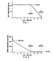
- FIG. 1 there is shown therein the preliminary boron and deuterium oxide requirements as a function of time during an eighteen month fuel cycle, assuming that the reactor is operated at a planned normal and average capacity factor (approximately 80%).
- the moderator flow tubes within the core are filled with substantially pure deuterium oxide. This concentration is to be maintained for approximately the first 60-70% of the fuel cycle, which for the example being used corresponds to approximately the first eleven months with one month being reserved for refueling.
- Figure 2 shows that for the same first eleven month period, the boron concentration is reduced from approximately 900 ppm to 50 ppm to compensate for the depletion of the fissle inventory and the buildup of fission products poisons.
- the high purity deuterium oxide concentration may be gradually diluted with light water to approximately 5% by weight to compensate for burnup induced reactivity changes.
- the boron concentration may be maintained nearly constant at approximately 50 ppm. Reactivity changes resulting from power, coolant temperature, or xenon concentration may be compensated for by varying some combination of boron concentration (if greater than 100 ppm), coolant temperature and control rod bank insertion.
- the deuterium oxide and light water mixtures which have been removed from the moderator control tubes within the core may be stored and upgraded to high purity deuterium oxide.
- the residual 5% deuterium oxide present at the end of the fuel cycle would be removed from the core and upgraded to a pure concentration.
- the moderator tubes Prior to startup with new fuel, the moderator tubes would be filled with substantially pure deuterium oxide by, for example, first purging the tubes with an inert gas. The fuel cycle described above would then be repeated.
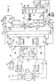
- Figure 3 illustrates one embodiment of a fluid moderator control system for effectuating the deuterium oxide concentrations shown in Figure 1.
- the overall system comprises a primary moderator control system recirculation circuit 10, a pressurizer circuit 11, a purification circuit 12, a letdown circuit 13, an upgrader circuit 14, and a feed/makeup and dilution circuit 15.
- the recirculation circuit 10 provides for circulation of deuterium oxide or a mixture of deuterium oxide and reactor coolant to and from the moderator control tubes within the nuclear core.
- the pressurizer circuit 11 maintains the pressure of the deuterium oxide a specified value below that : of the reactor coolant to prevent leakage, if any, into the reactor coolant supply system.
- the purification circuit 12 provides for continuous purification of a portion of the deuterium oxide flowing within the recirculation circuit 10.
- the letdown circuit 13 allows for removal and storage of all or a portion of the deuterium oxide within the recirculation circuit 10.
- the upgrader circuit 14 provides for upgrading the purity of diluted deuterium oxide to essentially pure condition.
- the feed/makeup and dilution circuit 15 provides the recirculation circuit 10 with its supply of deuterium oxide, makes up for any lost or removed fluid and supplies the recirculation circuit 10 with a desired concentration of a mixture of deuterium oxide and reactor coolant.
- the recirculation circuit 10, in the embodiment shown in Figure 1, provides for simultaneously circulating a moderator fluid to and from moderator tubes in each of four core quadrants, 20A, 20B, 20.C, and 20D.
- two identical primary circuits 10A and 10B are employed with each servicing two of the four core quadrants.
- the core quadrants are pictorially shown as discrete sections of a round core, each quadrant may contain moderator tubes arranged throughout the entire cross section of the core. In other words, each quadrant may occupy an undivided one-fourth of the core cross section. Since primary circuit 10A is identical to 10B, the ensuing description will apply equally to either of the circuits.
- the deuterium oxide exits from each of the two core quadrants 20A and 20C and flows through parallel flow lines 21 having a pair of motor-operated block valves 22 and a check valve 23 therein.
- the exit flow joins together in line 24 and flows through a heat exchanger 25 having steam generator feedwater flowing through the shell side thereof.
- Heat exchanger 25 is employed to maintain the deuterium oxide at subcooled conditions to preclude boiling of the deuterium oxide primarily within the moderator flow tubes and secondarily within the recirculation circuit 10.
- Conventional component cooling water may be used within heat exchanger 25 in lieu of the steam generator feedwater. While such alternative cooling water may be simpler from a design and fabrication standpoint, it may result in a non-negligible power loss.
- the preferred cooling means is to use the deuterium oxide recirculation circuit 10 energy to heat steam generator feedwater.
- the deuterium oxide Upon exiting heat exchanger 25, the deuterium oxide enters the suction port of the main recirculation pump 26 which pumps the low neutron oderating fluid through orifice 27 into line 28 which feeds into parallel flow lines 29.
- the D 2 0 Upon branching into flow lines 29, the D 2 0 flows through motor-operated block valves 30 and a pair of one-way check valves 31. From check valves 31 the deuterium oxide enters line 32, whereupon it reenters core quadrants 20a and 20c for passage through the moderator flow control tubes within the core. The cycle then repeats itself.
- the recirculation circuit 10 in the event of a reactor trip, provides an emergency high pressure decay heat removal capability in that a continuous recirculation of deuterium oxide through the moderator flow tubes within the core provides core cooling.
- Pressurizing circuit 11 maintains the pressure of the deuterium oxide, or the mixture thereof, at a value of approximately 3.45 105 to 5.52.105 Pa (50 to 80 psi) below the pressure of the reactor coolant.
- the lower pressure of the low neutron moderating fluid minimizes leakage of the same into the primary reactor coolant system. It is equally important to maintain the pressure of the low neutron moderating fluid as high as possible to maintain a subcooled condition within the moderator control tubes so as to absolutely minimize the flow rate of the deuterium oxide within recirculation circuit 10.
- the optimum operating pressure of the moderator control system is approximately 3.45.105 Pa (50 psi) below the pressure of the reactor coolant system. Pressurizer circuit 11 is utilized for this purpose.
- Throttling orifice 27 is used to assure a pressure lowerthan the optimum lower operating pressure of the deuterium oxide, or a mixture thereof. In this manner, the pressurizing circuit 11 controls the pressure.
- a portion of the low neutron moderating fluid is diverted from line 24 through a motor-operated block valve 35 into pressurizer tank 36 which is pressure controlled by cooler 37. Cooler 37 is cooled by component coolant water by means of line 38 and valve 39. Output from pressurizer tank 36 flows through line 40 through valve 41 back into line 28 downstream of orifice 27.
- Purification circuit 12 maintains the purity of the deuterium oxide or a mixture thereof flowing through recirculation circuit 10.
- Purification circuit 12 uses the head created by recirculation pump 26 to flow a desired portion of the flow within recirculation circuit 10 through valve 45, through a regenerative heat exchanger 46 and through a purification cooler 47 with the former being cooled by filtered low neutron moderating fluid and the latter by component cooling water. Upon exiting cooler 47, the fluid is passed through a filter 48 and parallel arranged ion exchange columns 49. The now purified fluid enters the shell side of heat exchanger 46 where it is regeneratively heated prior to flowing through valve 50 into the suction port of pump 26. It is to be noted that purification circuit 12 provides for continuous purification of a portion of the flow through recirculation circuit 10 with valve 45 providing flow rate control. Valve 51 provides for bypassing of ion exchange columns 49.
- Letdown system 13 provides for removal of all or a portion of the low neutron moderating fluid from the moderator control tubes within the nuclear core. Such removal may be for purposes of dilution of the deuterium oxide with reactor coolant (light water) as during the eleventh month of the fuel cycle example previously noted or for after complete removal of the low concentration deuterium oxide mixture following the seventeenth month of the fuel cycle.
- Letdown circuit 13 interfaces with purification circuit 12 at the outlet of ion exchange columns 49. In this instance, valve 55 is closed while valves 56 are open permitting the fluid to flow into storage tanks 59. Throttling orifices 57 and throttling valves 58 successively reduce the pressure from that of the recirculating circuit 10 to that of the storage tanks 59.
- Upgrader circuit 14 receives a mixture of deuterium oxide and light water in various concentrations and then upgrades the incoming mixture to a desired purity or concentration. Upgrad- ers of the type illustrated comprising a packed rectification column are known in the art having been used in the Canadian heavy water reactors. The flow circuit associated with the upgrader circuit 14 is, however, within the scope of the invention herein. Upgrader circuit 14 interfaces at the inlet end with letdown circuit 13 and at its outlet end with the feed/makeup circuit 15.
- the vapor from feed evaporator 65 rises to the head 68 of column 66 where it is condensed as a result of the component coolant water flowing therethrough and then flows back down column 66 to the bottom sump 69.
- a portion of the head product is simultaneously drawn off through line 70, cooled in heat exchanger 71 and stored in head product storage tank 72 for use as a diluent for pure deuterium oxide during the later stage of the next fuel cycle.
- the bottom product comprising high purity deuterium oxide
- the bottom product is transferred by pump 73 through line 74, cooler 75 into bottom storage tank 76 fortemporary storage and for subsequent use during the early stage of the next fuel cycle.
- a portion of the bottom product is continuously cycled by pump 73 through line 77, evaporator 78 and back into sump 69 for purposes of maintaining the purity of the bottom product within column 66.
- the final portion of the inventive system comprises the feed/makeup circuit 15 which makes up for any lost inventory of deuterium oxide within recirculation circuit 10.
- either pure deuterium oxide or the diluent or a combination thereof is drawn from tanks 72 and 76 through valves 85 and 86 to the suction port of pump 87 which flows the moderator control fluid through motor valve 88, check valve 89 and into recirculation circuits 10A and 10B through valves 45.
- the above-described system may be automatically controlled or controlled by the reactor- operating personnel. In either event, certain critical parameters must be- closely watched. The pressure and temperature of the deuterium oxide and mixtures thereof could be closely monitored. This can be accomplished manually by use of a Barringer concentration analyzer or other similar device.
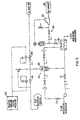
- FIG. 4 illustrates another embodiment of the inventive fluid moderator control system.
- the recirculation circuit 110 is essentially unchanged from the previously described embodiment.
- the associated pressurizer circuit, purification circuit, letdown circuit, upgrader circuit and the feed/makeup circuit are not shown for purposes of clarity. It is, of course, to be understood that such circuits are necessary for proper and complete functioning of the system.
- a reactor pressure vessel 112 is connected to a primary loop 113 which includes hot leg piping 114, steam generator 115, cross over piping 116, main coolant pump 117 and cold leg piping 118.
- the shell side of fluid moderator heat exchanger 120 is flow connected to a primary coolant circuit 121 and to an emergency core coolant and decay heat removal circuit 122.
- recirculation circuit operates normally as previously explained.
- the heat removed by heat exchanger 120 is utilized to heat primary coolant.
- Flow from the cold leg piping 118 passes through line 125 which contains two series connected motor operated block valves 126 and 127 and check valve 128.
- the bypassed primary coolant flow is heated by the heat rejected from the deuterium oxide, or a mixture thereof, in heat exchanger 120.
- the now heated bypassed primary coolant flow passes within line 129, containing valves 130 and 131 prior to being returned to the cross over piping leg 116.
- the pressure head created by main coolant pump 117 provides the driving pressure to accomplish the bypass reactor coolant flow.
- the emergency core coolant and decay heat removal circuit 122 functions to provide decay heat removal during such times as there is little or no primary coolant flow through the primary system of the reactor, and to provide energy core cooling following a loss-of-coolant accident.
- a high pressure head pump 135 is arranged to take suction from the reactor coolant system upper plenum through line 136, or the hot leg through line 137 and deliver the same to the tube side of a RHR (residual heat removal) heat exchanger 138, through the shell side of recirculation heat exchanger 120 and into the reactor vessel 112 downcomer region. Energy is thus rejected from circuit 110 to the reactor coolant via the recirculation heat exchanger 120 and the RHR heat exchanger 138.
- Component cooling water may be used in the shell side of heat exchanger 138 which may then reject the decay heat energy to service system water and ultimately to the main heat sink , such as a river, lake or the like.
- Circuit 122 as stated may also be used to provide emergency core cooling.
- pump 135 would take suction from an emergency water storage tank 139 and channel this coolant through the shell side of recirculation heat exchanger 120 and into the reactor vessel 112 downcomer region.
- the operating recirculation circuit 110 would, of course, be used in removing heat from the core.
- the hot flow from line 140 which may comprise reactor coolant may be injected into the hot leg piping 114, while the cold flow line would be fed from line 141 from.cold leg 118.
- the differential pressure across main coolant pump 117 would provide this circuit with the necessary driving force.
- An alternate pressurizing circuit for the inventive fluid moderator control system may comprise a circuit 150 such as that shown in Figure 5.
- the fluid moderator pressure is controlled by a surge tank 151 having an inert gas blanket such as helium over a liquid level of deuterium oxide in combination with pressure control valves.
- a pressure input signal from the reactor coolant system 152 is utilized by two air- operated pressure control valves 153 and 154 to track any fluctuation in the reactor coolant system pressure and maintains a desired pressure within the recirculation system 10 or 110 which is partially shown in Figure 5.
- Figure 5 also illustrates an alternate method of diluting the high purity deuterium oxide to achieve the low concentration mixture required during the later state of the fuel cycle.
- the diluent circuit 160 interfaces with recirculation circuit 10 or 110 at surge tank 151.
- Light water is injected into surge tank 151 by means of a positive displacement pump 162 coupled to a light water supply source 161.
- the light water diluent is preheated in the shell side 163 of the recirculation heat exchanger prior to being introduced into surge tank 151.
- a fluid moderator control system which provides for a uniform high purity of a low neutron moderating fluid within the core of a nuclear reactor during the early stage of the fuel cycle and which provides for a desired low concentration of the low neutron moderating fluid within the core during the later stage of the fuel cycle to permit a fluid moderator spectral shift.
Description
- This invention relates in general to the field of spectral shift, pressurized water nuclear reactors and in particular to a control system for a low neutron moderating fluid utilized to achieve the spectral shift.
- In conventional, state of the art, pressurized light water nuclear reactors, the reactor core is designed to contain excess reactivity. As the reactor operates, the excess reactivity is very gradually consumed until such point as the reactor core will no longer sustain the nuclear reaction and then the reactor must be refueled. Usually this occurs over the period of a year. It is very advantageous to maximize the time between reactor refuelings (extend the life of the core) since refueling requires complete shutdown of the reactor and is quite time consuming. Extending the life of the core is usually accomplished by providing the core with a significant amount of excess reactivity.
- Typically, control over the fission process, or reactivity control, including control necessitated by the excess reactivity is accomplished by varying the amount of neutron-absorbing materials within the core of the reactor. Control rods which contain neutron-absorbing materials and are movable into and out of the core provide one method of controlling the reactivity. Burnable and nonburnable poisons dissolved in the reactor coolant provide another method of reactivity control. As the reactivity decreases, due to reactor operation, the poisons are gradually removed by being burned by reactor operation or are physically removed by a separate system designed for such purpose. Most often, a combination of dissolved poisons and control rods are used to control the reactor and the excess reactivity.
- Unfortunately, control with control rods and poisons, absorb neutrons which could otherwise be used in a productive manner. For example, the neutrons produced by the excess reactivity could be used to convert fertile materials within the fuel assemblies to plutonium or fissile uranium which can then be fissioned and contribute to an even further extension of core life. Thus, while the use of control rods and dissolved poisons provided very effective reactor control, their use comprises a relatively inefficient depletion of high cost uranium. It would be, therefore, advantageous to control the excess reactivity, but not suppress the neutrons associated with the excess reactivity, in order to further extend core life or time between refuelings, and to lower fuel costs. It is known that fuel element enrichment can be reduced and the conversion ratio of the producing fissile materials can be increased by employing a "hardened" (nuclear energy) spectrum during the first part of the fuel cycle to reduce excessive reactivity and to increase the conversion of fertile material to fissile material; then employing a "softer" (lower energy) neutron spectrum during the latter part of the fuel cycle to increase reactivity and extend the core life by fissioning the previously generated fissile material. One such method utilizing the above is known as spectral shift control which provides a reactor with an extended core life while reducing the amount of neutron-absorbing material in the reactor core. One example of such method of control comprises a mechanical spectral shift reactor whereby hollow displacer rods are provided within fuel assemblies within the core (which, of course, displace an equal volume of water within the fuel assemblies) and which are mechanically withdrawn or punctured to accomplish water flooding of the available volume. In the early stages of core life, the neutron spectrum is hardened by the displacement of a portion of the water within the core by the displacer rods. The spectrum is later softened by the addition of water within the core by the aforesaid rod withdrawal or puncturing. U.S. Patent 4,432,930 entitled "Spectral Shift Reactor Control Method" and assigned to Westinghouse Electric Corporation, discloses one such mechanical spectral shift reactor.
- Another method of achieving a spectral shift is to utilize heavy water or deuterium oxide to replace an equivalent volume of core water during the early stages of core life then to gradually reduce the volume of heavy water and replace it with regular reactor coolant (light water) during the later stages of core life. The less effective moderator, heavy water, allows for less fuel enrichment and a higher ratio of converting fertile material to fissile material which in combination provides for a reduction of fuel costs and an extension of core life.
- As can be well appreciated, the success of the spectral shift is, in part, dependent upon a system for controlling the amount of the moderating fluid (including a mixture thereof) supplied to the reactor consistent with the reactivity needs of the reactor at any given time and to provide for removing the fluid from the reactor and for upgrading the same for later use.
- It is, therefore, the principal object of the present invention to provide a control system, external of the pressure vessel for supplying a low neutron moderating fluid and/or a mixture of a low neutron moderating fluid and the normal reactor coolant to the reactor pressure vessel.
- With this object in view, the present invention resides in a nuclear reactor having a core structure with tubes incorporated therein for receiving different fluids for purposes of spectral shift, a control system for controlling the supply of fluid to said tubes, characterized by means for circulating said fluids to and from said pressure vessel; means for pressurizing the fluids in said circulation means to maintain a predetermined fluid pressure; means for supplying a moderator fluid to said circulation means; means for removing said moderator fluid from said circulation means; and means for varying the concentration of said fluids supplied to said circulation means.
- The invention will become more readily apparent from the following description of a preferred embodiment thereof shown, by way of example only, in the following drawings, in which:
- Figure 1 is a graph of a fluid moderator concentration versus reactor fuel operating time;
- Figure 2 is a graph of boron concentration in the reactor coolant versus reactor fuel operating time;
- Figure 3 is a schematic flow diagram of one embodiment of the inventive fluid moderator control system;
- Figure 4 is a schematic flow diagram of the inventive control system adapted to provide core heat removal; and
- Figure 5 is a schematic flow diagram of another embodiment of the inventive control system.
- Referring now to the drawings, specifically Figures 1 and 2, there is shown therein the preliminary boron and deuterium oxide requirements as a function of time during an eighteen month fuel cycle, assuming that the reactor is operated at a planned normal and average capacity factor (approximately 80%). Initially, the moderator flow tubes within the core are filled with substantially pure deuterium oxide. This concentration is to be maintained for approximately the first 60-70% of the fuel cycle, which for the example being used corresponds to approximately the first eleven months with one month being reserved for refueling. Figure 2 shows that for the same first eleven month period, the boron concentration is reduced from approximately 900 ppm to 50 ppm to compensate for the depletion of the fissle inventory and the buildup of fission products poisons.
- During the last part of the fuel cycle, or from the twelfth to the seventeenth month of an eighteen month fuel cycle, the high purity deuterium oxide concentration may be gradually diluted with light water to approximately 5% by weight to compensate for burnup induced reactivity changes. During this same period of time, the boron concentration may be maintained nearly constant at approximately 50 ppm. Reactivity changes resulting from power, coolant temperature, or xenon concentration may be compensated for by varying some combination of boron concentration (if greater than 100 ppm), coolant temperature and control rod bank insertion.
- During the twelfth to the seventeenth month period, the deuterium oxide and light water mixtures which have been removed from the moderator control tubes within the core may be stored and upgraded to high purity deuterium oxide. After cold shutdown, conditions of the reactor are reached but prior to any refueling operations, the residual 5% deuterium oxide present at the end of the fuel cycle would be removed from the core and upgraded to a pure concentration. Prior to startup with new fuel, the moderator tubes would be filled with substantially pure deuterium oxide by, for example, first purging the tubes with an inert gas. The fuel cycle described above would then be repeated.
- Figure 3 illustrates one embodiment of a fluid moderator control system for effectuating the deuterium oxide concentrations shown in Figure 1. In general, the overall system comprises a primary moderator control system recirculation circuit 10, a
pressurizer circuit 11, apurification circuit 12, aletdown circuit 13, anupgrader circuit 14, and a feed/makeup anddilution circuit 15. - The recirculation circuit 10 provides for circulation of deuterium oxide or a mixture of deuterium oxide and reactor coolant to and from the moderator control tubes within the nuclear core. The
pressurizer circuit 11 maintains the pressure of the deuterium oxide a specified value below that : of the reactor coolant to prevent leakage, if any, into the reactor coolant supply system. Thepurification circuit 12 provides for continuous purification of a portion of the deuterium oxide flowing within the recirculation circuit 10. Theletdown circuit 13 allows for removal and storage of all or a portion of the deuterium oxide within the recirculation circuit 10. Theupgrader circuit 14 provides for upgrading the purity of diluted deuterium oxide to essentially pure condition. The feed/makeup anddilution circuit 15 provides the recirculation circuit 10 with its supply of deuterium oxide, makes up for any lost or removed fluid and supplies the recirculation circuit 10 with a desired concentration of a mixture of deuterium oxide and reactor coolant. - The recirculation circuit 10, in the embodiment shown in Figure 1, provides for simultaneously circulating a moderator fluid to and from moderator tubes in each of four core quadrants, 20A, 20B, 20.C, and 20D. For maximum reliability, two identical
primary circuits primary circuit 10A is identical to 10B, the ensuing description will apply equally to either of the circuits. The deuterium oxide exits from each of the twocore quadrants block valves 22 and acheck valve 23 therein. The exit flow joins together inline 24 and flows through aheat exchanger 25 having steam generator feedwater flowing through the shell side thereof.Heat exchanger 25 is employed to maintain the deuterium oxide at subcooled conditions to preclude boiling of the deuterium oxide primarily within the moderator flow tubes and secondarily within the recirculation circuit 10. Conventional component cooling water may be used withinheat exchanger 25 in lieu of the steam generator feedwater. While such alternative cooling water may be simpler from a design and fabrication standpoint, it may result in a non-negligible power loss. Hence, the preferred cooling means is to use the deuterium oxide recirculation circuit 10 energy to heat steam generator feedwater. Upon exitingheat exchanger 25, the deuterium oxide enters the suction port of themain recirculation pump 26 which pumps the low neutron oderating fluid throughorifice 27 intoline 28 which feeds intoparallel flow lines 29. Upon branching intoflow lines 29, the D20 flows through motor-operatedblock valves 30 and a pair of one-way check valves 31. Fromcheck valves 31 the deuterium oxide entersline 32, whereupon it reenters core quadrants 20a and 20c for passage through the moderator flow control tubes within the core. The cycle then repeats itself. - It is to be noted that the recirculation circuit 10, in the event of a reactor trip, provides an emergency high pressure decay heat removal capability in that a continuous recirculation of deuterium oxide through the moderator flow tubes within the core provides core cooling.
-
Pressurizing circuit 11 maintains the pressure of the deuterium oxide, or the mixture thereof, at a value of approximately 3.45 105 to 5.52.105 Pa (50 to 80 psi) below the pressure of the reactor coolant. The lower pressure of the low neutron moderating fluid minimizes leakage of the same into the primary reactor coolant system. It is equally important to maintain the pressure of the low neutron moderating fluid as high as possible to maintain a subcooled condition within the moderator control tubes so as to absolutely minimize the flow rate of the deuterium oxide within recirculation circuit 10. The optimum operating pressure of the moderator control system is approximately 3.45.105 Pa (50 psi) below the pressure of the reactor coolant system.Pressurizer circuit 11 is utilized for this purpose. Throttlingorifice 27 is used to assure a pressure lowerthan the optimum lower operating pressure of the deuterium oxide, or a mixture thereof. In this manner, the pressurizingcircuit 11 controls the pressure. A portion of the low neutron moderating fluid is diverted fromline 24 through a motor-operatedblock valve 35 intopressurizer tank 36 which is pressure controlled by cooler 37.Cooler 37 is cooled by component coolant water by means ofline 38 andvalve 39. Output frompressurizer tank 36 flows throughline 40 throughvalve 41 back intoline 28 downstream oforifice 27. -
Purification circuit 12, as previously stated, maintains the purity of the deuterium oxide or a mixture thereof flowing through recirculation circuit 10.Purification circuit 12 uses the head created byrecirculation pump 26 to flow a desired portion of the flow within recirculation circuit 10 throughvalve 45, through aregenerative heat exchanger 46 and through a purification cooler 47 with the former being cooled by filtered low neutron moderating fluid and the latter by component cooling water. Upon exiting cooler 47, the fluid is passed through afilter 48 and parallel arrangedion exchange columns 49. The now purified fluid enters the shell side ofheat exchanger 46 where it is regeneratively heated prior to flowing throughvalve 50 into the suction port ofpump 26. It is to be noted thatpurification circuit 12 provides for continuous purification of a portion of the flow through recirculation circuit 10 withvalve 45 providing flow rate control.Valve 51 provides for bypassing ofion exchange columns 49. -
Letdown system 13 provides for removal of all or a portion of the low neutron moderating fluid from the moderator control tubes within the nuclear core. Such removal may be for purposes of dilution of the deuterium oxide with reactor coolant (light water) as during the eleventh month of the fuel cycle example previously noted or for after complete removal of the low concentration deuterium oxide mixture following the seventeenth month of the fuel cycle.Letdown circuit 13 interfaces withpurification circuit 12 at the outlet ofion exchange columns 49. In this instance,valve 55 is closed whilevalves 56 are open permitting the fluid to flow intostorage tanks 59. Throttling orifices 57 and throttling valves 58 successively reduce the pressure from that of the recirculating circuit 10 to that of thestorage tanks 59. -
Upgrader circuit 14 receives a mixture of deuterium oxide and light water in various concentrations and then upgrades the incoming mixture to a desired purity or concentration. Upgrad- ers of the type illustrated comprising a packed rectification column are known in the art having been used in the Canadian heavy water reactors. The flow circuit associated with theupgrader circuit 14 is, however, within the scope of the invention herein.Upgrader circuit 14 interfaces at the inlet end withletdown circuit 13 and at its outlet end with the feed/makeup circuit 15. - A mixture of deuterium oxide and light water exits from
storage tanks 59 into afeed evaporator 65 which may be heated by low pressure secondary steam. The vapor from thefeed evaporator 65 flows intoupgrader column 66 throughline 67. The vapor fromfeed evaporator 65 rises to thehead 68 ofcolumn 66 where it is condensed as a result of the component coolant water flowing therethrough and then flows back downcolumn 66 to thebottom sump 69. A portion of the head product is simultaneously drawn off throughline 70, cooled in heat exchanger 71 and stored in headproduct storage tank 72 for use as a diluent for pure deuterium oxide during the later stage of the next fuel cycle. The bottom product, comprising high purity deuterium oxide, is transferred bypump 73 throughline 74, cooler 75 into bottom storage tank 76 fortemporary storage and for subsequent use during the early stage of the next fuel cycle. A portion of the bottom product is continuously cycled bypump 73 throughline 77,evaporator 78 and back intosump 69 for purposes of maintaining the purity of the bottom product withincolumn 66. - The final portion of the inventive system comprises the feed/
makeup circuit 15 which makes up for any lost inventory of deuterium oxide within recirculation circuit 10. In this mode of operation, either pure deuterium oxide or the diluent or a combination thereof is drawn fromtanks 72 and 76 throughvalves pump 87 which flows the moderator control fluid throughmotor valve 88,check valve 89 and intorecirculation circuits valves 45. The above-described system may be automatically controlled or controlled by the reactor- operating personnel. In either event, certain critical parameters must be- closely watched. The pressure and temperature of the deuterium oxide and mixtures thereof could be closely monitored. This can be accomplished manually by use of a Barringer concentration analyzer or other similar device. By specifically pointing out the above- noted parameters, it is not intended to imply that all the remaining parameters associated with the control system are not important or necessary. Proper functioning and monitoring of the entire system is essential. - Figure 4 illustrates another embodiment of the inventive fluid moderator control system. In this embodiment, the recirculation circuit 110 is essentially unchanged from the previously described embodiment. The associated pressurizer circuit, purification circuit, letdown circuit, upgrader circuit and the feed/makeup circuit are not shown for purposes of clarity. It is, of course, to be understood that such circuits are necessary for proper and complete functioning of the system. For further purposes of simplicity of description and explanation, only one recirculation circuit 110 associated with one core quadrant 111 is shown. A
reactor pressure vessel 112 is connected to aprimary loop 113 which includeshot leg piping 114,steam generator 115, cross over piping 116,main coolant pump 117 andcold leg piping 118. - The shell side of fluid
moderator heat exchanger 120 is flow connected to aprimary coolant circuit 121 and to an emergency core coolant and decayheat removal circuit 122. - During normal reactor operation, recirculation circuit operates normally as previously explained. In this embodiment, however, the heat removed by
heat exchanger 120 is utilized to heat primary coolant. Flow from the cold leg piping 118 passes throughline 125 which contains two series connected motor operatedblock valves heat exchanger 120. The now heated bypassed primary coolant flow passes withinline 129, containingvalves piping leg 116. The pressure head created bymain coolant pump 117 provides the driving pressure to accomplish the bypass reactor coolant flow. - The emergency core coolant and decay
heat removal circuit 122 functions to provide decay heat removal during such times as there is little or no primary coolant flow through the primary system of the reactor, and to provide energy core cooling following a loss-of-coolant accident. A highpressure head pump 135 is arranged to take suction from the reactor coolant system upper plenum throughline 136, or the hot leg throughline 137 and deliver the same to the tube side of a RHR (residual heat removal)heat exchanger 138, through the shell side ofrecirculation heat exchanger 120 and into thereactor vessel 112 downcomer region. Energy is thus rejected from circuit 110 to the reactor coolant via therecirculation heat exchanger 120 and theRHR heat exchanger 138. Component cooling water may be used in the shell side ofheat exchanger 138 which may then reject the decay heat energy to service system water and ultimately to the main heat sink , such as a river, lake or the like. -
Circuit 122 as stated may also be used to provide emergency core cooling. In this mode of operation, pump 135 would take suction from an emergencywater storage tank 139 and channel this coolant through the shell side ofrecirculation heat exchanger 120 and into thereactor vessel 112 downcomer region. The operating recirculation circuit 110 would, of course, be used in removing heat from the core. - Should it be desired not to use recirculation circuit 110 for fluid moderator control purposes, the hot flow from
line 140 which may comprise reactor coolant may be injected into thehot leg piping 114, while the cold flow line would be fed fromline 141 from.cold leg 118. The differential pressure acrossmain coolant pump 117 would provide this circuit with the necessary driving force. - An alternate pressurizing circuit for the inventive fluid moderator control system may comprise a
circuit 150 such as that shown in Figure 5. In this alternative, the fluid moderator pressure is controlled by asurge tank 151 having an inert gas blanket such as helium over a liquid level of deuterium oxide in combination with pressure control valves. A pressure input signal from thereactor coolant system 152 is utilized by two air- operatedpressure control valves - Figure 5 also illustrates an alternate method of diluting the high purity deuterium oxide to achieve the low concentration mixture required during the later state of the fuel cycle. In this embodiment, the
diluent circuit 160 interfaces with recirculation circuit 10 or 110 atsurge tank 151. Light water is injected intosurge tank 151 by means of apositive displacement pump 162 coupled to a lightwater supply source 161. The light water diluent is preheated in theshell side 163 of the recirculation heat exchanger prior to being introduced intosurge tank 151. - In accordance with the above-description, taken in conjunction with the accompanying drawings, a fluid moderator control system is provided, which provides for a uniform high purity of a low neutron moderating fluid within the core of a nuclear reactor during the early stage of the fuel cycle and which provides for a desired low concentration of the low neutron moderating fluid within the core during the later stage of the fuel cycle to permit a fluid moderator spectral shift.
Claims (16)
Applications Claiming Priority (2)
| Application Number | Priority Date | Filing Date | Title |
|---|---|---|---|
| US62684384A | 1984-07-02 | 1984-07-02 | |
| US626843 | 1984-07-02 |
Publications (2)
| Publication Number | Publication Date |
|---|---|
| EP0170033A1 EP0170033A1 (en) | 1986-02-05 |
| EP0170033B1 true EP0170033B1 (en) | 1989-04-26 |
Family
ID=24512089
Family Applications (1)
| Application Number | Title | Priority Date | Filing Date |
|---|---|---|---|
| EP85107667A Expired EP0170033B1 (en) | 1984-07-02 | 1985-06-21 | Fluid moderator control system -d2o/h2o |
Country Status (4)
| Country | Link |
|---|---|
| EP (1) | EP0170033B1 (en) |
| JP (1) | JPS6120889A (en) |
| KR (1) | KR860001444A (en) |
| ES (1) | ES8705677A1 (en) |
Families Citing this family (2)
| Publication number | Priority date | Publication date | Assignee | Title |
|---|---|---|---|---|
| JPS5627454A (en) * | 1979-08-15 | 1981-03-17 | Hitachi Ltd | Information processor |
| KR101015438B1 (en) * | 2010-09-29 | 2011-02-22 | 한국기계연구원 | Loca test system |
Family Cites Families (5)
| Publication number | Priority date | Publication date | Assignee | Title |
|---|---|---|---|---|
| BE568102A (en) * | 1957-05-29 | |||
| FR1369644A (en) * | 1962-09-12 | 1964-08-14 | Hitachi Ltd | Materials test reactor |
| DE2005391A1 (en) * | 1970-02-06 | 1971-08-12 | Kraftwerk Union Ag | Chemical reactivity control system for nuclear reactors |
| US4032401A (en) * | 1972-06-30 | 1977-06-28 | Westinghouse Electric Corporation | Combined solid and liquid system for controlling nuclear reactors |
| US4432930A (en) * | 1980-12-16 | 1984-02-21 | Westinghouse Electric Corp. | Spectral shift reactor control method |
-
1985
- 1985-06-21 EP EP85107667A patent/EP0170033B1/en not_active Expired
- 1985-06-28 JP JP60140686A patent/JPS6120889A/en active Granted
- 1985-06-28 ES ES544692A patent/ES8705677A1/en not_active Expired
- 1985-07-02 KR KR1019850004750A patent/KR860001444A/en not_active Application Discontinuation
Also Published As
| Publication number | Publication date |
|---|---|
| ES544692A0 (en) | 1987-05-01 |
| EP0170033A1 (en) | 1986-02-05 |
| KR860001444A (en) | 1986-02-26 |
| ES8705677A1 (en) | 1987-05-01 |
| JPH0321880B2 (en) | 1991-03-25 |
| JPS6120889A (en) | 1986-01-29 |
Similar Documents
| Publication | Publication Date | Title |
|---|---|---|
| US2917444A (en) | Neutronic reactor control | |
| US8571166B2 (en) | Core of light water reactor and fuel assembly | |
| EP2421005B1 (en) | Nuclear reactor | |
| CN102576573A (en) | Method of operating a pressurized-water nuclear reactor for reaching a plutonium equilibrium cycle | |
| EP0167069B1 (en) | Gas displacement spectral shift reactor | |
| EP0071326B1 (en) | Nuclear power plant | |
| US3305450A (en) | Nuclear reactors with pressurizer operating with noncondensible gas | |
| US4129475A (en) | Method of operating a nuclear reactor | |
| EP0170033B1 (en) | Fluid moderator control system -d2o/h2o | |
| US5271052A (en) | Enriched boron-10 boric acid control system for a nuclear reactor plant | |
| US3356583A (en) | Liquid moderated nuclear reactor | |
| Matzie et al. | Design of the safe integral reactor | |
| Thomet | Feasibility studies of a soluble boron-free 900-MW (electric) PWR, core physics–I: Motivations, assembly design, and core control | |
| US3629059A (en) | Fluid control and safety rods for nuclear reactors | |
| EP0300745A2 (en) | Reactivity control method of light-water cooled, lightwater moderated nuclear reactor core and apparatus therefor | |
| US3211624A (en) | Method and means for controlling the start of a homogeneous nuclear reactor | |
| US3151031A (en) | Method of regulating the operation of homogeneous nuclear reactors | |
| JP2718855B2 (en) | Nuclear fuel channel and its own safe water cooled tube reactor | |
| CN85105161A (en) | Liquid moderator control system one heavy water D 2O/ light-water H 2O | |
| Li et al. | Conceptual core design of HAPPY200 reactor | |
| Melese-d'Hospital et al. | Status of gas-cooled fast breeder reactor programs | |
| Hongqi et al. | Moderator Heat Transport and Steam Systems | |
| Millar | Fuel management in CANDU reactors | |
| Sofer | Steam-cooled Power Reactor Evaluation: Steam-cooled Fast Breeder Reactor | |
| Cameron et al. | The heavy-water-moderated reactor |
Legal Events
| Date | Code | Title | Description |
|---|---|---|---|
| PUAI | Public reference made under article 153(3) epc to a published international application that has entered the european phase |
Free format text: ORIGINAL CODE: 0009012 |
|
| AK | Designated contracting states |
Designated state(s): BE CH FR GB IT LI |
|
| 17P | Request for examination filed |
Effective date: 19860709 |
|
| 17Q | First examination report despatched |
Effective date: 19871027 |
|
| ITF | It: translation for a ep patent filed |
Owner name: DR. ING. A. RACHELI & C. |
|
| GRAA | (expected) grant |
Free format text: ORIGINAL CODE: 0009210 |
|
| AK | Designated contracting states |
Kind code of ref document: B1 Designated state(s): BE CH FR GB IT LI |
|
| PGFP | Annual fee paid to national office [announced via postgrant information from national office to epo] |
Ref country code: BE Payment date: 19890531 Year of fee payment: 5 |
|
| ET | Fr: translation filed | ||
| PGFP | Annual fee paid to national office [announced via postgrant information from national office to epo] |
Ref country code: CH Payment date: 19890627 Year of fee payment: 5 |
|
| R20 | Corrections of a patent specification |
Effective date: 19890615 |
|
| PGFP | Annual fee paid to national office [announced via postgrant information from national office to epo] |
Ref country code: GB Payment date: 19890930 Year of fee payment: 5 |
|
| PLBE | No opposition filed within time limit |
Free format text: ORIGINAL CODE: 0009261 |
|
| STAA | Information on the status of an ep patent application or granted ep patent |
Free format text: STATUS: NO OPPOSITION FILED WITHIN TIME LIMIT |
|
| 26N | No opposition filed | ||
| PG25 | Lapsed in a contracting state [announced via postgrant information from national office to epo] |
Ref country code: GB Effective date: 19900621 |
|
| PG25 | Lapsed in a contracting state [announced via postgrant information from national office to epo] |
Ref country code: BE Effective date: 19900630 Ref country code: LI Effective date: 19900630 Ref country code: CH Effective date: 19900630 |
|
| BERE | Be: lapsed |
Owner name: WESTINGHOUSE ELECTRIC CORP. Effective date: 19900630 |
|
| GBPC | Gb: european patent ceased through non-payment of renewal fee | ||
| REG | Reference to a national code |
Ref country code: CH Ref legal event code: PL |
|
| PGFP | Annual fee paid to national office [announced via postgrant information from national office to epo] |
Ref country code: FR Payment date: 19920416 Year of fee payment: 8 |
|
| PG25 | Lapsed in a contracting state [announced via postgrant information from national office to epo] |
Ref country code: FR Effective date: 19940228 |
|
| REG | Reference to a national code |
Ref country code: FR Ref legal event code: ST |