EP0169424B1 - Control rod end plug with a stabilizing configuration - Google Patents
Control rod end plug with a stabilizing configuration Download PDFInfo
- Publication number
- EP0169424B1 EP0169424B1 EP85108364A EP85108364A EP0169424B1 EP 0169424 B1 EP0169424 B1 EP 0169424B1 EP 85108364 A EP85108364 A EP 85108364A EP 85108364 A EP85108364 A EP 85108364A EP 0169424 B1 EP0169424 B1 EP 0169424B1
- Authority
- EP
- European Patent Office
- Prior art keywords
- end plug
- control rod
- tip
- central axis
- plug
- Prior art date
- Legal status (The legal status is an assumption and is not a legal conclusion. Google has not performed a legal analysis and makes no representation as to the accuracy of the status listed.)
- Expired - Lifetime
Links
Images

Classifications
-
- G—PHYSICS
- G21—NUCLEAR PHYSICS; NUCLEAR ENGINEERING
- G21C—NUCLEAR REACTORS
- G21C7/00—Control of nuclear reaction
-
- G—PHYSICS
- G21—NUCLEAR PHYSICS; NUCLEAR ENGINEERING
- G21C—NUCLEAR REACTORS
- G21C7/00—Control of nuclear reaction
- G21C7/06—Control of nuclear reaction by application of neutron-absorbing material, i.e. material with absorption cross-section very much in excess of reflection cross-section
- G21C7/08—Control of nuclear reaction by application of neutron-absorbing material, i.e. material with absorption cross-section very much in excess of reflection cross-section by displacement of solid control elements, e.g. control rods
- G21C7/10—Construction of control elements
- G21C7/117—Clusters of control rods; Spider construction
-
- Y—GENERAL TAGGING OF NEW TECHNOLOGICAL DEVELOPMENTS; GENERAL TAGGING OF CROSS-SECTIONAL TECHNOLOGIES SPANNING OVER SEVERAL SECTIONS OF THE IPC; TECHNICAL SUBJECTS COVERED BY FORMER USPC CROSS-REFERENCE ART COLLECTIONS [XRACs] AND DIGESTS
- Y02—TECHNOLOGIES OR APPLICATIONS FOR MITIGATION OR ADAPTATION AGAINST CLIMATE CHANGE
- Y02E—REDUCTION OF GREENHOUSE GAS [GHG] EMISSIONS, RELATED TO ENERGY GENERATION, TRANSMISSION OR DISTRIBUTION
- Y02E30/00—Energy generation of nuclear origin
- Y02E30/30—Nuclear fission reactors
Definitions
- This invention relates generally to nuclear reactors and, more particularly, to rod and guide thimble arrangements such as used therein.
- the reactor core is composed of a plurality of elongate fuel assemblies each of which contains a plurality of elongate fuel elements or rods.
- a liquid coolant is pumped upwardly through the core in order to extract heat generated in the core for the production of useful energy.
- the heat output of the core is usually regulated by the movement of control rods containing neutron absorbing material, such as B 4 C, or by the movement of water displacer rods, such as described in U.S. Patent No. 4,432,934.
- each fuel assembly typically includes a plurality of hollow cylindrical guide tubes or thimbles in which the cylindrical control rods or water displacer rods are axially movable. Some of the coolant flow is usually diverted into the lower end of each guide thimble in order to cool the rod therein which ordinarily generates heat in the nuclear transformation associated with its neutron absorbing function.
- US-A-4,292,132 proposes to add on the lower end of the control rod a spring device which provides a uniform, resilient interference fit against the guide thimble wall and thereby prevents the rod tip from impacting it.
- the control rod has formed at its lower tip a hydraulic bearing adapted to produce forces which counteract any forces tending to drive the control rod tip against the guide thimble wall.
- the invention resides in a control rod for use in a nuclear reactor including means for supporting the control rod for axial movement thereof in a guide thimble which is adapted to have reactor coolant flowing therethrough and along the control rod portion disposed therein, said control rod having an end plug at the end thereof which has a substantially conical tip and which is located within the guide thimble when in use, characterized in that said conical tip of the end plug has an asymmetrical configuration causing said reactor coolant, when flowing therepast, to impart to the end plug a lateral force sufficient to urge and hold the end plug steady against the inner wall of said guide thimble.
- the invention proposes to achieve the same desired result merely by changing the shape of the control rod end plug.
- one of the causes of coolant flow- induced vibration is vortex shedding around the tip of conventional end plugs which are symmetrical with respect to their central axis or, in other words, to the longitudinal axis of the control rod.
- the asymmetrical configuration of the end plug which reduces vortex shedding also produces said lateral force by rendering the coolant flow velocities around the end plug tip non-symmetrical, the magnitude of the lateral force being a function of the coolant flow rate and the particular shape of the end plug tip.
- a fuel assembly generally designated with numeral 10
- an upper core support plate 12 disposed above and extending across the top of fuel assembly 10
- a spider assembly 14 disposed above the upper core support plate.
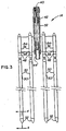
- the fuel assembly 10 basically comprises a lower end structure or bottom nozzle 16 for supporting the assembly on a lower core plate (not shown) in the core region of a reactor (not shown); a plurality of guide tubes or thimbles 18 longitudinally extending upward from the bottom nozzle 16; a plurality of transverse grids 20 axially spaced along the guide thimbles 18; an organized array of elongate fuel rods 22 transversely spaced and supported by the grids 20; an instrumentation tube 24 in the center of the fuel assembly; and an upper end structure or top nozzle 26 affixed to the upper ends of the guide thimbles 18.
- the upper core support 12 extends across all of the fuel assemblies, such as assembly 10, of the reactor core. It has a multiplicity of flow passages, such as flow passage 28, for reactor coolant to flow therethrough, and each guide thimble 18 has one such flow passage 28 in axial alignment therewith to enable a control rod 30 to be inserted.
- control rods 30 are connected to the spider assembly 14 which supports the rods for axial movement thereof, effected by means of a conventional drive mechanism (not shown), within the guide thimbles 18.
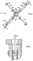
- the spider assembly 14 comprises a central hub 32, a plurality of vanes 34 extending radially outward from the hub 32, and a plurality of fingers 36 on the vanes 34 to which the control rods 30 are connected.
- the hub 32 is in the form of a tube having on its upper end an internally threaded segment 40 for connection to the drive mechanism (not shown) which is operable to raise and lower the spider assembly 14 together with the control rods 30 thereon, as well known in the art.
- the tubular hub 32 houses a common load absorbing mechanism comprising a coil spring 42 held in a state of compression, and a nipple 44 adapted to be seated in a shallow cavity (not shown) formed in the top of the core plate 12 to assist in assuring proper alignment of the control rods 30 with the core plate passages 28 and the guide thimbles 18.
- the main purposes of the load absorbing mechanism is to prevent shock loading of the core plate 12 and of the fuel assembly 10 as the spider assembly 14 abuts the top of the core plate 12 upon full insertion of the control rods 30 into the guide thimbles 18.
- Each control rod 30 is supported from one of the fingers 36 of the spider assembly 14, each finger 36 having a lower end portion 36 thereof drilled and internally threaded for threadedly receiving an upper end portion 48 of the associated control rod 30.
- Each control rod 30 includes tubular cladding 50 and an end plug 52 affixed to the lower end of the cladding.
- the rod contains neutron absorbing material, usually in the form of pellets stacked within the cladding 50.
- Other control rod designs adapt the rods for use as water displacer rods employed for controlling the reactivity of the reactor through displacement of some of the neutron moderating reactor coolant, as described in the above-mentioned US-A-4,432,934.
- control rods such as rods 30, into and from the guide thimbles.
- the control rods are fully inserted during reactor shutdown, and some are withdrawn when the reactor is operating at full power. "Withdrawn” is to be understood in this context as meaning that the control rods 30 are not completely withdrawn from the guide thimbles 18 but still extend into them a short distance, such as 15 cm, for example, as shown in Fig. 5.
- control rod 30 When the control rod 30 are fully inserted into the guide thimbles 18 and, thus, within the reactor core (not shown), they are subject to the generation of heat. Therefore, and in order to prevent the pellets therein from melting, provision is made for cooling the control rods.
- the lower portions of the guide thimbles are, for this purpose, provided with openings (not shown) enabling some of the pumped coolant entering through the bottom of the fuel assembly 10 to flow into and through the guide thimbles 18 and, in doing so, to cool the control rods 30.
- each control rod with a lower end plug shaped in such manner as to cause coolant flowing toward this end plug to flow therepast at non-symmetric velocities and thereby to impart to the end plug a lateral stabilizing force F (Fig. 5), which presses or biases the lower end of the control rod 30 against the inner wall 58 of the thimble 18 as seen in Fig. 5, and thereby prevents the rod 30 from vibrating.
- a lateral stabilizing force F Fig. 5
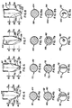
- an ordinary end plug 52 having the usual conical or tapered outer surface 60 can be rendered suitable for the purposes of the invention by having a flat 62 formed, e.g. machined, on one side of the otherwise axially symmetrical surface 60.
- the original profile of the surface portion which the flat 62 replaces is shown in broken lines in Fig. 4 from which it is seen that the flat 62 begins at the cylindrical body 64 of the end plug 52 and, extending down the tip 66, crosses the central axis 68 of the end plug 52 to form a terminal end 70 on the opposite side of the axis 68.
- Figs. 4a to 4c provide comparative cross-sectional views of the end plug 52 which allow one to form a more complete three-dimensional mental image of the stabilizing configuration of the end plug.
- the end plugs 52 of Figs. 3 and 5 have the stabilizing configuration of Fig. 4.
- Fig. 6 illustrates a second asymmetrical design of an end plug 72 wherein a pair of flats 74, 76 are formed on opposite sides of the tapered outer surface 78. Again, the original profile of the lower tip 80 of the plug 72 is indicated in broken lines.
- the flat 74 on the left is substantially identical to the flat 62 of the design of Fig. 4 in that it crosses the longitudinal axis 82.
- the flat 76 on the right begins higher on the cylindrical body 86 of the end plug than the flat 74 and thus forms a shallower angle with the axis 82 than does the flat 74.
- Fig. 7 represents a third asymmetrical design of an end plug 88 wherein the original symmetrical taper of the plug tip (shown in broken line) has been reduced, such as by machining, to form a tip 90 which has a steeper and more pointed conical configuration and has an axis 92 which is inclined relative to, and which intersects, the central axis 94 of the end plug 88 to form a terminal end 96 offset to one side of the axis 94.
- Fig. 8 illustrates a fourth asymmetrical design of an end plug 98 having a concave surface 100 formed on a side of the tapered outer surface 102 of the plug.
- the concave surface 100 begins in the cylindrical body 104, crosses the central axis 106 of the end plug 98, and forms a lower terminal end 108 on the tip 110 at the opposite side of the axis 106.
- a feature common to all of the asymmetrical tip designs shown in Figs. 4 and 6 to 8 is that the terminal tip ends 70, 84, 96 and 108, respectively, all are offset to one side of the central axes 68, 82, 94 and 106 of the respective end plugs 52, 72, 88 and 98. This ensures non-symmetric coolant-flow velocity patterns imparting to the respective end plugs lateral forces acting in the direction in which the tip ends are offset from said central axes. Moreover, each of the asymmetrical end plug shapes reduces the possibility of flow- induced vibration caused by vortex shedding such as experienced with symmetrical end plug designs. Thus, although some of the asymmetrical end plug stabilizing configurations shown herein may be preferred to others from a manufacturing standpoint, they all perform the same useful functions in an advantageous manner.
Landscapes
- Physics & Mathematics (AREA)
- Engineering & Computer Science (AREA)
- Chemical & Material Sciences (AREA)
- Chemical Kinetics & Catalysis (AREA)
- Plasma & Fusion (AREA)
- General Engineering & Computer Science (AREA)
- High Energy & Nuclear Physics (AREA)
- Monitoring And Testing Of Nuclear Reactors (AREA)
- Vibration Dampers (AREA)
Applications Claiming Priority (2)
| Application Number | Priority Date | Filing Date | Title |
|---|---|---|---|
| US06/634,729 US4820058A (en) | 1984-07-26 | 1984-07-26 | Control rod end plug with a stabilizing configuration |
| US634729 | 1984-07-26 |
Publications (3)
| Publication Number | Publication Date |
|---|---|
| EP0169424A2 EP0169424A2 (en) | 1986-01-29 |
| EP0169424A3 EP0169424A3 (en) | 1986-12-17 |
| EP0169424B1 true EP0169424B1 (en) | 1990-01-03 |
Family
ID=24544989
Family Applications (1)
| Application Number | Title | Priority Date | Filing Date |
|---|---|---|---|
| EP85108364A Expired - Lifetime EP0169424B1 (en) | 1984-07-26 | 1985-07-05 | Control rod end plug with a stabilizing configuration |
Country Status (6)
| Country | Link |
|---|---|
| US (1) | US4820058A (cg-RX-API-DMAC7.html) |
| EP (1) | EP0169424B1 (cg-RX-API-DMAC7.html) |
| JP (1) | JPS6138592A (cg-RX-API-DMAC7.html) |
| KR (1) | KR930009571B1 (cg-RX-API-DMAC7.html) |
| DE (1) | DE3575229D1 (cg-RX-API-DMAC7.html) |
| ES (1) | ES8900265A1 (cg-RX-API-DMAC7.html) |
Families Citing this family (9)
| Publication number | Priority date | Publication date | Assignee | Title |
|---|---|---|---|---|
| US4863678A (en) * | 1985-12-09 | 1989-09-05 | Westinghouse Electric Corp. | Rod cluster having improved vane configuration |
| JPH07104426B2 (ja) * | 1988-09-14 | 1995-11-13 | 三菱原子燃料株式会社 | スパイダー組立体 |
| US4990304A (en) * | 1989-01-27 | 1991-02-05 | Westinghouse Electric Corp. | Instrumentation tube features for reduction of coolant flow-induced vibration of flux thimble tube |
| US5215707A (en) * | 1991-09-10 | 1993-06-01 | Siemens Power Corporation | Instrument thimble tube shroud |
| US5282233A (en) * | 1992-09-28 | 1994-01-25 | Combustion Engineering, Inc. | Low pressure drop easy load end cap |
| US5321732A (en) * | 1993-07-16 | 1994-06-14 | Combustion Engineering Inc. | Control rod housing support bars with radiation shields |
| US5323435A (en) * | 1993-07-16 | 1994-06-21 | Combustion Engineering Inc. | Control rod housing support bars with wing assemblies |
| US5570402A (en) * | 1994-08-04 | 1996-10-29 | Combustion Engineering, Inc. | Control rod housing support system with radiation shield rings |
| US6526116B1 (en) * | 1997-07-02 | 2003-02-25 | Westinghouse Electric Company Llc | Nuclear fuel assembly with hydraulically balanced mixing vanes |
Family Cites Families (7)
| Publication number | Priority date | Publication date | Assignee | Title |
|---|---|---|---|---|
| US3285820A (en) * | 1961-03-09 | 1966-11-15 | Soc Anglo Belge Vulcain Sa | Nuclear reactors |
| DE2066109C2 (de) * | 1970-10-12 | 1982-04-22 | Hochtemperatur-Reaktorbau GmbH, 5000 Köln | Abschaltstab für Kernreaktoren mit einer Schüttung kugelförmiger Betriebselemente |
| US3979258A (en) * | 1971-03-16 | 1976-09-07 | Hochtemperatur-Kernkraftwerke Gmbh (Hkg) Gemeinsames Europaisches Unternehmen | Nuclear reactor |
| US3728218A (en) * | 1971-05-24 | 1973-04-17 | Brown Boveri Krupp Reaktor | Control rods for nuclear reactors |
| US4292132A (en) * | 1979-01-02 | 1981-09-29 | Combustion Engineering, Inc. | Hydraulically centered control rod |
| US4311560A (en) * | 1979-05-04 | 1982-01-19 | Combustion Engineering, Inc. | Stabilizing device for control rod tip |
| US4313796A (en) * | 1979-07-30 | 1982-02-02 | Combustion Engineering, Inc. | Guide post modification for nuclear fuel assembly |
-
1984
- 1984-07-26 US US06/634,729 patent/US4820058A/en not_active Expired - Fee Related
-
1985
- 1985-07-05 DE DE8585108364T patent/DE3575229D1/de not_active Expired - Lifetime
- 1985-07-05 EP EP85108364A patent/EP0169424B1/en not_active Expired - Lifetime
- 1985-07-22 ES ES545437A patent/ES8900265A1/es not_active Expired
- 1985-07-24 JP JP16217885A patent/JPS6138592A/ja active Granted
- 1985-07-26 KR KR1019850005377A patent/KR930009571B1/ko not_active Expired - Lifetime
Also Published As
| Publication number | Publication date |
|---|---|
| EP0169424A2 (en) | 1986-01-29 |
| US4820058A (en) | 1989-04-11 |
| KR860001439A (ko) | 1986-02-26 |
| JPS6138592A (ja) | 1986-02-24 |
| JPH0543074B2 (cg-RX-API-DMAC7.html) | 1993-06-30 |
| ES545437A0 (es) | 1989-06-01 |
| EP0169424A3 (en) | 1986-12-17 |
| ES8900265A1 (es) | 1989-06-01 |
| KR930009571B1 (ko) | 1993-10-07 |
| DE3575229D1 (de) | 1990-02-08 |
Similar Documents
| Publication | Publication Date | Title |
|---|---|---|
| US4675154A (en) | Nuclear fuel assembly with large coolant conducting tube | |
| US4957697A (en) | Nuclear fuel rod support grid with generally S-shaped spring structures | |
| US4990304A (en) | Instrumentation tube features for reduction of coolant flow-induced vibration of flux thimble tube | |
| EP0384220B1 (en) | Nuclear fuel-rod support grid | |
| EP0379947B1 (en) | Fuel rod for use in a nuclear fuel assembly | |
| US4326921A (en) | Control rod guide thimble for nuclear reactor fuel assemblies | |
| EP0169424A2 (en) | Control rod end plug with a stabilizing configuration | |
| EP0212920B1 (en) | Full length control rod employing axially inhomogeneous absorber materials for zero reactivity redistribution factor | |
| EP0175455B1 (en) | A nuclear reactor control rod having a reduced worth tip | |
| EP0169421B1 (en) | Control rod for a nuclear reactor | |
| US4957698A (en) | Advanced boiling water reactor fuel assembly design | |
| US5572560A (en) | BWR fuel assembly having fuel rods with variable fuel rod pitches | |
| KR930008243B1 (ko) | 비등수형 원자로용 제어봉 | |
| EP0170943B1 (en) | Nuclear fuel assembly with improved spectral shift rods | |
| US4587078A (en) | Initial charge core of fast breeder and method of charging the core with fuel | |
| US4728487A (en) | Standardized reduced length burnable absorber rods for a nuclear reactor | |
| US6823035B1 (en) | Control rod | |
| US5878100A (en) | Fuel assembly for a boiling water reactor | |
| EP0526777B1 (en) | Boiling water reactor fuel assembly comprising water rods | |
| US4933137A (en) | Nuclear fuel assembly with means for retarding detector tube wear | |
| EP0183069A1 (en) | Water displacer rod for use in a spectral shift nuclear reactor | |
| US3728218A (en) | Control rods for nuclear reactors | |
| US4836977A (en) | Standardized reduced length burnable absorber rods for a nuclear reactor | |
| US5343508A (en) | Spacer grid retainer | |
| KR100330356B1 (ko) | 저 기포반응도용 저 농축우라늄 핵연료 |
Legal Events
| Date | Code | Title | Description |
|---|---|---|---|
| PUAI | Public reference made under article 153(3) epc to a published international application that has entered the european phase |
Free format text: ORIGINAL CODE: 0009012 |
|
| AK | Designated contracting states |
Designated state(s): BE DE FR GB IT SE |
|
| PUAL | Search report despatched |
Free format text: ORIGINAL CODE: 0009013 |
|
| AK | Designated contracting states |
Kind code of ref document: A3 Designated state(s): BE DE FR GB IT SE |
|
| 17P | Request for examination filed |
Effective date: 19870603 |
|
| 17Q | First examination report despatched |
Effective date: 19890221 |
|
| GRAA | (expected) grant |
Free format text: ORIGINAL CODE: 0009210 |
|
| PGFP | Annual fee paid to national office [announced via postgrant information from national office to epo] |
Ref country code: FR Payment date: 19891229 Year of fee payment: 6 |
|
| AK | Designated contracting states |
Kind code of ref document: B1 Designated state(s): BE DE FR GB IT SE |
|
| PG25 | Lapsed in a contracting state [announced via postgrant information from national office to epo] |
Ref country code: IT Free format text: LAPSE BECAUSE OF FAILURE TO SUBMIT A TRANSLATION OF THE DESCRIPTION OR TO PAY THE FEE WITHIN THE PRESCRIBED TIME-LIMIT;WARNING: LAPSES OF ITALIAN PATENTS WITH EFFECTIVE DATE BEFORE 2007 MAY HAVE OCCURRED AT ANY TIME BEFORE 2007. THE CORRECT EFFECTIVE DATE MAY BE DIFFERENT FROM THE ONE RECORDED. Effective date: 19900103 |
|
| ET | Fr: translation filed | ||
| PGFP | Annual fee paid to national office [announced via postgrant information from national office to epo] |
Ref country code: BE Payment date: 19900126 Year of fee payment: 6 |
|
| REF | Corresponds to: |
Ref document number: 3575229 Country of ref document: DE Date of ref document: 19900208 |
|
| PGFP | Annual fee paid to national office [announced via postgrant information from national office to epo] |
Ref country code: DE Payment date: 19900515 Year of fee payment: 6 |
|
| PLBE | No opposition filed within time limit |
Free format text: ORIGINAL CODE: 0009261 |
|
| STAA | Information on the status of an ep patent application or granted ep patent |
Free format text: STATUS: NO OPPOSITION FILED WITHIN TIME LIMIT |
|
| 26N | No opposition filed | ||
| PGFP | Annual fee paid to national office [announced via postgrant information from national office to epo] |
Ref country code: SE Payment date: 19910131 Year of fee payment: 6 |
|
| PG25 | Lapsed in a contracting state [announced via postgrant information from national office to epo] |
Ref country code: SE Effective date: 19910706 |
|
| PG25 | Lapsed in a contracting state [announced via postgrant information from national office to epo] |
Ref country code: BE Effective date: 19910731 |
|
| BERE | Be: lapsed |
Owner name: WESTINGHOUSE ELECTRIC CORP. Effective date: 19910731 |
|
| PG25 | Lapsed in a contracting state [announced via postgrant information from national office to epo] |
Ref country code: FR Effective date: 19920331 |
|
| PG25 | Lapsed in a contracting state [announced via postgrant information from national office to epo] |
Ref country code: DE Effective date: 19920401 |
|
| REG | Reference to a national code |
Ref country code: FR Ref legal event code: ST |
|
| EUG | Se: european patent has lapsed |
Ref document number: 85108364.2 Effective date: 19920210 |
|
| REG | Reference to a national code |
Ref country code: GB Ref legal event code: IF02 |
|
| PGFP | Annual fee paid to national office [announced via postgrant information from national office to epo] |
Ref country code: GB Payment date: 20040726 Year of fee payment: 20 |
|
| PG25 | Lapsed in a contracting state [announced via postgrant information from national office to epo] |
Ref country code: GB Free format text: LAPSE BECAUSE OF EXPIRATION OF PROTECTION Effective date: 20050704 |
|
| REG | Reference to a national code |
Ref country code: GB Ref legal event code: PE20 |