US5321732A - Control rod housing support bars with radiation shields - Google Patents
Control rod housing support bars with radiation shields Download PDFInfo
- Publication number
- US5321732A US5321732A US08/092,063 US9206393A US5321732A US 5321732 A US5321732 A US 5321732A US 9206393 A US9206393 A US 9206393A US 5321732 A US5321732 A US 5321732A
- Authority
- US
- United States
- Prior art keywords
- control rod
- support
- rod drive
- drive housing
- cups
- Prior art date
- Legal status (The legal status is an assumption and is not a legal conclusion. Google has not performed a legal analysis and makes no representation as to the accuracy of the status listed.)
- Expired - Lifetime
Links
Images


Classifications
-
- G—PHYSICS
- G21—NUCLEAR PHYSICS; NUCLEAR ENGINEERING
- G21C—NUCLEAR REACTORS
- G21C7/00—Control of nuclear reaction
- G21C7/06—Control of nuclear reaction by application of neutron-absorbing material, i.e. material with absorption cross-section very much in excess of reflection cross-section
- G21C7/08—Control of nuclear reaction by application of neutron-absorbing material, i.e. material with absorption cross-section very much in excess of reflection cross-section by displacement of solid control elements, e.g. control rods
- G21C7/12—Means for moving control elements to desired position
- G21C7/16—Hydraulic or pneumatic drive
-
- G—PHYSICS
- G21—NUCLEAR PHYSICS; NUCLEAR ENGINEERING
- G21C—NUCLEAR REACTORS
- G21C19/00—Arrangements for treating, for handling, or for facilitating the handling of, fuel or other materials which are used within the reactor, e.g. within its pressure vessel
- G21C19/02—Details of handling arrangements
-
- Y—GENERAL TAGGING OF NEW TECHNOLOGICAL DEVELOPMENTS; GENERAL TAGGING OF CROSS-SECTIONAL TECHNOLOGIES SPANNING OVER SEVERAL SECTIONS OF THE IPC; TECHNICAL SUBJECTS COVERED BY FORMER USPC CROSS-REFERENCE ART COLLECTIONS [XRACs] AND DIGESTS
- Y02—TECHNOLOGIES OR APPLICATIONS FOR MITIGATION OR ADAPTATION AGAINST CLIMATE CHANGE
- Y02E—REDUCTION OF GREENHOUSE GAS [GHG] EMISSIONS, RELATED TO ENERGY GENERATION, TRANSMISSION OR DISTRIBUTION
- Y02E30/00—Energy generation of nuclear origin
- Y02E30/30—Nuclear fission reactors
Definitions
- This invention relates to supports and, more particularly, to boiling water reactor control rod drive housing supports. Still more particularly, this invention relates to control rod drive housing support bars with radiation shields.
- control rod drive housing supports are generally located underneath the reactor vessel near the control rod housings.
- the control rod drive housing supports limit the travel of and support a control rod in the event that a control rod drive housing is ruptured.
- the supports prevent a nuclear excursion as a result of a housing failure, thus protecting the fuel barrier.
- control rod drive housing supports consist of hanger rods that are attached and supported at their upper end at a beam structure immediately underneath the reactor pressure vessel and support bars which are bolted between the hanger rods below the control rod drives.
- Another grid of bars is installed on the support bars to transfer the load of a ruptured control rod drive housing to the support bars.
- a pair of grid bars support each control rod drive. Each pair of grid bars are held together by two grid clamps and a bolt.
- control rod drive housing support of this invention may comprise a first means for supporting a control rod drive in the case of a housing failure; and second means for supporting the control rod drive in the case of a housing failure and shielding persons working under the reactor vessel from radiation, the second means being supported by the first supporting means, and wherein the second means can be automatically raised and lowered from a non-support position where the control rod drive is not supported to a support position where the control rod drive is supported.
- first supporting means may comprise a plurality of support members provided in rows on opposing sides of a lower portion of a plurality of control rod drives and the second supporting means may comprise a plurality of support cups, each of the support cups receiving, and shielding a lower portion of the control rod drive and supporting the control rod drive in the case of a housing failure.
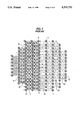
- FIG. 1 is a top schematic view of the control rod drive housing support bars of the prior art.
- FIG. 2 is a top view of the control rod drive housing support bars with radiation shields of the present invention.
- FIG. 3 is a side view of the control rod drive housing support bars with radiation shields of the present invention.
- FIG. 4 is a top view of another embodiment of the control rod drive housing support bars with radiation shields of the present invention.
- FIG. 5 is a side view of the control rod drive housing support bars with radiation shields of FIG. 4.
- FIG. 6 is a top view of another embodiment of the control rod drive housing support bars with radiation shields of the present invention.
- FIG. 7 is a side view of the control rod drive housing supports with the radiation shields of FIG. 6.
- FIG. 8A is a top view of a support bar used with the support assembly shown in FIGS. 2 and 3.
- FIG. 8B is a cross-sectional side view of the support bar of FIG. 8A.
- FIG. 9A is a top view of another support bar used with support assembly shown in FIGS. 2 and 3.
- FIG. 9B is a cross-sectional side view of the support bar of FIG. 9A.
- FIG. 10A is a top view of a support bar used with the support assembly of FIGS. 4 and 5.
- FIG. 10B is a side view of a support bar used with the support assembly of FIGS. 4 and 5.
- FIG. 10C is a top view of a support bar used with the support assembly of FIGS. 6 and 7.
- FIG. 10D is a side view of a support bar used with the support assembly of FIGS. 6 and 7.
- FIG. 11 is a side view of a control rod drive housing support with a radiation shield according to another embodiment of the present invention.
- FIG. 12 is a side view of the support bar of the control rod drive housing supports of an embodiment of the present invention.
- FIG. 13 is a side view of the support bar of the control rod drive housing supports of another embodiment of the present invention.
- FIG. 14 is a side view of the support bar of the control rod drive housing supports of another embodiment of the present invention.
- Boiling water reactors use control rods in the reactor vessel for controlling the reaction therein.
- the control rods are generally contained in a grid-like fashion in a control rod housing with a drive unit for raising the control rods into the assembly of the fuel rods.
- control rod drive housing supports Located underneath the reactor vessel near the control rod housings are control rod drive housing supports for limiting the travel of a control rod in the event that a control rod housing is ruptured.
- FIG. 1 A top view of the control rod drive housing supports of the prior art is shown schematically in FIG. 1.
- the positions shown at 10 correspond to a control rod drive position.
- the control rod drive housing supports of the prior art consist of hanger rods 11 supported by a beam underneath the reactor pressure vessel (not shown) spaced throughout the grid of control rod drive positions.
- Support bars 12 are bolted between the hanger rods 11.
- Grid bars 13 are installed on the support bars 12 to support the control rod drive and transfer the load of the control rod drive to the support bars 12.
- a pair of grid bars 13 support each control rod drive.
- Each pair of grid bars is held together by two grid clamps 14 and a bolt (not shown).
- control rod drive housing supports of the prior art is shown to the right of line A--A only with the support bars 12 and is shown with the support bars 12 and grid bars 13 to the left of the line A--A.
- the grid bars 13 would be used throughout the entire housing supports.
- the grid bars 13 and clamps 14 In order to replace a control rod drive, using this prior art control rod drive housing supports, the grid bars 13 and clamps 14 must be removed. Because the grid bars 13 are interlocking, they must be removed starting from the periphery, resulting in a cumbersome and time consuming process.
- control rod drive housing supports of the present invention will be described.
- the control rod drive positions and hanger rods are again shown at 10 and 11, respectively.
- the grid bars 13 and clamps 14 of the prior art are replaced with radiation shields 25 which both supports the control rod drive in the case of control rod drive housing rupture and provides radiation protection for the personnel working under the reactor pressure vessel.
- the design of the radiation shields 25 are such that they can be easily handled and removed by a control rod drive removal/installation machine. Thus, all awkward and dangerous, manual handling of the control rod drive and supports as with the grid bars of the prior art is eliminated. Further, changing of the control rod drives is much easier and faster.
- the radiation shields protect the personnel working under the reactor pressure vessel from exposure to radiation.
- the support bars 12 of the prior art are replaced with support bars 22 or support bars 32 placed in rows along opposing sides of the control rod drive positions and are oriented ninety degrees to the old bar support bars 12.
- An end of each support bar 22 is supported on a hanger rod 11 through a hub 23.
- the support bar 12 and hubs 23 are shown in FIGS. 8A and 8B.
- the support bars 12 of the prior art were one foot long.
- the length of support bars 22 of the present invention may vary depending on the reactor and the placement of the hangers. Preferably, the length of the support bars 22 is two feet.
- the support assembly of the present invention is comprised of radiation shields 25 in the shape of cups interlocked together.
- the radiation shield cups 25 surround a bottom portion 16 of a control rod drive 15 beneath a flange 17 and flange bolts 18 on the control rod drive.
- a rim 26 is provided on the radiation shield cups to support the flange 17 or flange bolt 18 of the control rod drive 15 in the case of a housing rupture.
- the cups 25 include an opening 29 for passage of an electric cord of the control rod drive 15 and connection to the control rod drive installation/removal machine.
- the radiation shield cups 25 are each provided with tabs 28 on opposing sides. A tab 28 on a shield cup 25 interlocks with a tab 28 on an adjacent shield cup 25, thereby locking the shield cups 25 together.
- the radiation shield cups 25 are supported on the support bars 22 through radiation shield support bars 27.
- Two support bars 27 at one end thereof support opposing sides of a radiation shield cup 25 through the rim 26.
- the support bars 22 support the other end of the radiation shield support bars 27.
- the support bars 22, in turn, are installed on the hangar rods 11 through hubs 23.
- the radiation shield 25 Prior to operation of the plant, the radiation shield 25 is lifted into position by the mast of the control rod drive removal/installation machine and when at the appropriate height, it is turned 45° and locked in position on top of the support bars 22. When the radiation shield 25 is removed by the control rod drive removal/installation machine, it is turned 45° and unlocked and lowered to a position where it may easily be manually lifted and moved to the side. As a result, considerable time is saved and workers are subject to considerably less radiation compared to the handling of the grid bar supports of the prior art.
- the radiation shield cups 25 are provided below the control rod drive flange bolt 18 with some clearance to allow for thermal expansion of the control rod drive when the plant is in operation. As a result, a gap 34 exists between the control rod drive flange 17 and flange bolt 18 and the radiation shield cups 25. The gap 34 must be sufficient to allow the control rod drive 15 to expand as the system heats up during operation, preferably three quarters of an inch.
- the control rod drive 15 expands and the gap 34 between the flange 17 and the bolt 18 and the cups 25 is reduced so that the flange bolt 18 and cups 25 are almost touching.
- the gap is reduced to about one quarter of an inch.
- the radiation shield cup 25 cannot move when the plant is in operation and is thereby further locked into position.
- the control rod drives reduce in size and the gap between the flange 17 and flange bolt 18 and the radiation shield cups 25 increases to its original clearance. At such clearance the radiation shield 25 may be lowered to a non-operating position.
- notches can be provided between the radiation shield cups 25 and the support bars to provide an additional locking means for the cups 25.
- a radiation shield cup 65 as shown in FIG. 11, may be used.
- the radiation shield cup 65 is provided with a first annular hole 66 and a second annular hole 67. Between the first and second holes 66 and 67 is a ledge 68.
- the cup 65 may be provided around the bottom portion 16 of control rod drive 15 with a clearance between the ledge 6 and lower flange bolts 19.
- the cups support the control rod drive through bolts 19. Accordingly, the control drive can be supported through flange bolts 18 as shown by FIG. 3 or through flange bolts 19 as shown in FIG. 11.
- the present invention includes three alternative support bar assemblies to cover various situations around the control rod drive.
- core detectors may be placed throughout the grid of control rod drives. Specifically Start-up Range Monitors/Intermediate Range Monitors (“SRM/IRM”) core detectors and Local Power Range Monitors (“LPRM”) core detectors may be provided throughout the grid of control rod drives to monitor the reactor core. While the present invention will be described in connection with SRM/IRM detectors and LPRM detectors, it should be recognized that the invention could also be used in connection with other instruments.
- detectors are shown placed throughout the grid of control rods at 30.
- a detector position support bar 32 may be used at a detector position 30 to support a radiation shield cup and accommodate a detector.
- support bar 32 has a curved portion 35 sized to bend around a detector 30 and hubs 33 for attachment to the hangar rods 11.
- the detector position support bar 32 supports a radiation shield cup 25 without interfering with the detector 30 or its drive 31 and gear box 32. The support bar 32 thereby allows easy service of gear box 36. Further, when a detector is being replaced, the detector can be lowered without removing the detector 30.
- the detector position support bars 32 can be used just at the detector positions or can be used at any or all positions in order to standardize the housing support.
- FIGS. 4, 5, 10A and 10B Another alternative support bar is shown in FIGS. 4, 5, 10A and 10B.
- a detector position support bar 42 having hubs 43 for attachment to hangar rods 11 is provided with a throughhole 45.
- the hole 45 in support bar 42 receives the lower portion of the detector therethrough.
- An upper portion 46 of hole 45 in the support bar 42 is sized to accommodate the gear box 36 on the detector 30 allowing the support bar 42 to be installed when the detector is already in place.
- a support bar 52 with hubs 53 for attachment to hangar rods 11 with a hole 55 may be used.
- the hole 55 receives the detector 30 therethrough.
- the gear box 36 is below the bottom of the support bar 52 when the support bar 52 is in use allowing the detectors to be removed while the support bar is in place.
- FIGS. 12, 13 and 14 Alternative support bars for each of the situations described in the above embodiments of the present invention are shown in FIGS. 12, 13 and 14.
- every other support bar has either an upper or a lower hub.
- the total number of support bars used is increased.
- the removal and installation of a specific support is simplified because a maximum of three support bars need be removed in order to access any position.
- only one support bar need be removed. This is to be compared with the main embodiment described above where all the support bars have to be removed from the periphery until the specific bar to be accessed is reached.
- FIG. 12 illustrates a row of support bars 22 without any detector positions.
- the support bars 22 alternately have upper hubs 61 and lower hubs 62.
- support bars 32 could also be provided with upper and lower hubs.
- FIG. 13 illustrates a row of support bars with detector positions.
- the support bars 52 are also shown having alternately, upper hubs 61 and lower hubs 62.
- FIG. 14 also illustrates a row of support bars with detector positions. Both the support bars 42 and the support bar 22 are shown.
- the support bars 42 are also shown with upper hubs 61 and lower hubs 62.
- the present invention provides greatly increased radiation protection for persons working under the reactor vessel and increased support of the control rod drive housing while also allowing quick and easy replacement of a control rod drive.
Landscapes
- Physics & Mathematics (AREA)
- Engineering & Computer Science (AREA)
- Chemical & Material Sciences (AREA)
- Chemical Kinetics & Catalysis (AREA)
- Plasma & Fusion (AREA)
- General Engineering & Computer Science (AREA)
- High Energy & Nuclear Physics (AREA)
- Monitoring And Testing Of Nuclear Reactors (AREA)
- Structure Of Emergency Protection For Nuclear Reactors (AREA)
- Vibration Dampers (AREA)
Abstract
Description
Claims (21)
Priority Applications (4)
| Application Number | Priority Date | Filing Date | Title |
|---|---|---|---|
| US08/092,063 US5321732A (en) | 1993-07-16 | 1993-07-16 | Control rod housing support bars with radiation shields |
| TW083100691A TW233362B (en) | 1993-07-16 | 1994-01-27 | Control rod housing support bars with radiation shields |
| ES09401482A ES2106658B1 (en) | 1993-07-16 | 1994-07-07 | SUPPORT BARS FOR CONTROL ROD FRAMES WITH RADIATION SHIELDS. |
| JP6183067A JPH0755981A (en) | 1993-07-16 | 1994-07-13 | Supporting body for housing of control-rod driving device of boiling water reactor |
Applications Claiming Priority (1)
| Application Number | Priority Date | Filing Date | Title |
|---|---|---|---|
| US08/092,063 US5321732A (en) | 1993-07-16 | 1993-07-16 | Control rod housing support bars with radiation shields |
Publications (1)
| Publication Number | Publication Date |
|---|---|
| US5321732A true US5321732A (en) | 1994-06-14 |
Family
ID=22231275
Family Applications (1)
| Application Number | Title | Priority Date | Filing Date |
|---|---|---|---|
| US08/092,063 Expired - Lifetime US5321732A (en) | 1993-07-16 | 1993-07-16 | Control rod housing support bars with radiation shields |
Country Status (4)
| Country | Link |
|---|---|
| US (1) | US5321732A (en) |
| JP (1) | JPH0755981A (en) |
| ES (1) | ES2106658B1 (en) |
| TW (1) | TW233362B (en) |
Cited By (1)
| Publication number | Priority date | Publication date | Assignee | Title |
|---|---|---|---|---|
| US5570402A (en) * | 1994-08-04 | 1996-10-29 | Combustion Engineering, Inc. | Control rod housing support system with radiation shield rings |
Citations (4)
| Publication number | Priority date | Publication date | Assignee | Title |
|---|---|---|---|---|
| US4752434A (en) * | 1985-01-28 | 1988-06-21 | Framatome | Control bar and drive mechanism coupling device |
| US4820058A (en) * | 1984-07-26 | 1989-04-11 | Westinghouse Electric Corp. | Control rod end plug with a stabilizing configuration |
| US4859409A (en) * | 1988-05-27 | 1989-08-22 | Westinghouse Electric Corp. | Reactor vessel lower internals temporary support |
| US4888149A (en) * | 1988-09-27 | 1989-12-19 | Combustion Engineering, Inc. | Wear-reduction-shield for thimbles |
Family Cites Families (3)
| Publication number | Priority date | Publication date | Assignee | Title |
|---|---|---|---|---|
| DE498319C (en) * | 1930-05-21 | Karl Groschoff | Idle pulley with lubrication tube | |
| FR2575581B1 (en) * | 1984-12-27 | 1987-03-06 | Framatome & Cie | DEVICE FOR MOVING AND HANGING A CLUSTER OF NUCLEAR REACTOR CONTROL PENCILS |
| FR2575582B1 (en) * | 1984-12-28 | 1987-03-06 | Framatome Sa | DEVICE AND METHOD FOR HANGING A STEERING ROD FOR A CONTROL CLUSTER IN A NUCLEAR REACTOR |
-
1993
- 1993-07-16 US US08/092,063 patent/US5321732A/en not_active Expired - Lifetime
-
1994
- 1994-01-27 TW TW083100691A patent/TW233362B/en active
- 1994-07-07 ES ES09401482A patent/ES2106658B1/en not_active Expired - Lifetime
- 1994-07-13 JP JP6183067A patent/JPH0755981A/en active Pending
Patent Citations (4)
| Publication number | Priority date | Publication date | Assignee | Title |
|---|---|---|---|---|
| US4820058A (en) * | 1984-07-26 | 1989-04-11 | Westinghouse Electric Corp. | Control rod end plug with a stabilizing configuration |
| US4752434A (en) * | 1985-01-28 | 1988-06-21 | Framatome | Control bar and drive mechanism coupling device |
| US4859409A (en) * | 1988-05-27 | 1989-08-22 | Westinghouse Electric Corp. | Reactor vessel lower internals temporary support |
| US4888149A (en) * | 1988-09-27 | 1989-12-19 | Combustion Engineering, Inc. | Wear-reduction-shield for thimbles |
Cited By (1)
| Publication number | Priority date | Publication date | Assignee | Title |
|---|---|---|---|---|
| US5570402A (en) * | 1994-08-04 | 1996-10-29 | Combustion Engineering, Inc. | Control rod housing support system with radiation shield rings |
Also Published As
| Publication number | Publication date |
|---|---|
| ES2106658B1 (en) | 1998-06-01 |
| JPH0755981A (en) | 1995-03-03 |
| ES2106658A1 (en) | 1997-11-01 |
| TW233362B (en) | 1994-11-01 |
Similar Documents
| Publication | Publication Date | Title |
|---|---|---|
| US5225150A (en) | Integrated head package for top mounted nuclear instrumentation | |
| KR100923047B1 (en) | Modular integrated head assembly | |
| EP0154113B1 (en) | Modular head assembly for a pressure vessel of a nuclear reactor | |
| KR100296455B1 (en) | Integral head rig, head area cable tray and missible shield for pressurized water reactor | |
| US6618460B2 (en) | Integrated head assembly for a nuclear reactor | |
| US4830814A (en) | Integrated head package for a nuclear reactor | |
| US7139359B2 (en) | Integrated head assembly for a nuclear reactor | |
| JP4596739B2 (en) | A platform for maintaining a nuclear reactor and a nuclear reactor maintenance method using the platform | |
| GB2100496A (en) | Standard integrated head package | |
| JPH0611592A (en) | Reactor-system containing apparatus | |
| US5323435A (en) | Control rod housing support bars with wing assemblies | |
| US4828789A (en) | Reactor vessel head permanent shield | |
| US3445971A (en) | High pressure vessel hold-together structure | |
| US4666657A (en) | Remotely adjustable intermediate seismic support | |
| EP0716423B1 (en) | Shroud for a nuclear reactor | |
| US5633901A (en) | Permanent pool cavity seal for nuclear reactor | |
| JPH08254592A (en) | Reactor pressure vessel and reactor-core-shroud exchanging method | |
| US5321732A (en) | Control rod housing support bars with radiation shields | |
| US5452334A (en) | Pressurized water reactor nuclear fuel assembly with disengaging upper tie plate corner post | |
| EP0077573B1 (en) | Rail apparatus around nuclear reactor pressure vessel and method of installing the same | |
| US5282232A (en) | Nuclear reactor upper internal equipment with cluster guide devices | |
| US5570402A (en) | Control rod housing support system with radiation shield rings | |
| US4859409A (en) | Reactor vessel lower internals temporary support | |
| US20030026377A1 (en) | Integrated head assembly for a nuclear reactor | |
| EP0186302B1 (en) | Shields for nuclear reactors |
Legal Events
| Date | Code | Title | Description |
|---|---|---|---|
| STPP | Information on status: patent application and granting procedure in general |
Free format text: APPLICATION UNDERGOING PREEXAM PROCESSING |
|
| AS | Assignment |
Owner name: COMBUSTION ENGINEERING INC., CONNECTICUT Free format text: ASSIGNMENT OF ASSIGNORS INTEREST;ASSIGNOR:BAVERSTEN, BENGT I.;REEL/FRAME:006707/0251 Effective date: 19930830 |
|
| FEPP | Fee payment procedure |
Free format text: PAYOR NUMBER ASSIGNED (ORIGINAL EVENT CODE: ASPN); ENTITY STATUS OF PATENT OWNER: LARGE ENTITY |
|
| FPAY | Fee payment |
Year of fee payment: 4 |
|
| AS | Assignment |
Owner name: ABB COMBUSTION ENGINEERING NUCLEAR POWER, INC., CO Free format text: ASSIGNMENT OF ASSIGNORS INTEREST;ASSIGNOR:COMBUSTION ENGINEERING, INC.;REEL/FRAME:010070/0603 Effective date: 19990630 |
|
| AS | Assignment |
Owner name: CE NUCLEAR POWER LLC, CONNECTICUT Free format text: MERGER AND CHANGE OF NAME;ASSIGNOR:ABB C-E NUCLEAR POWER, INC.;REEL/FRAME:011035/0466 Effective date: 20000428 Owner name: ABB C-E NUCLEAR POWER, INC., CONNECTICUT Free format text: MERGER/CHANGE OF NAME;ASSIGNOR:ABB COMBUSTION ENGINEERING NUCLEAR POWER, INC.;REEL/FRAME:011035/0483 Effective date: 19991216 |
|
| AS | Assignment |
Owner name: WESTINGHOUSE ELECTRIC CO. LLC, PENNSYLVANIA Free format text: MERGER;ASSIGNOR:CE NUCLEAR POWER LLC;REEL/FRAME:011742/0299 Effective date: 20010402 |
|
| FPAY | Fee payment |
Year of fee payment: 8 |
|
| FPAY | Fee payment |
Year of fee payment: 12 |