EP0169285A2 - Gerät zur Tiefenlockerung von Böden - Google Patents
Gerät zur Tiefenlockerung von Böden Download PDFInfo
- Publication number
- EP0169285A2 EP0169285A2 EP84306716A EP84306716A EP0169285A2 EP 0169285 A2 EP0169285 A2 EP 0169285A2 EP 84306716 A EP84306716 A EP 84306716A EP 84306716 A EP84306716 A EP 84306716A EP 0169285 A2 EP0169285 A2 EP 0169285A2
- Authority
- EP
- European Patent Office
- Prior art keywords
- leg
- foot
- tool
- support member
- tine
- Prior art date
- Legal status (The legal status is an assumption and is not a legal conclusion. Google has not performed a legal analysis and makes no representation as to the accuracy of the status listed.)
- Withdrawn
Links
Images

Classifications
-
- A—HUMAN NECESSITIES
- A01—AGRICULTURE; FORESTRY; ANIMAL HUSBANDRY; HUNTING; TRAPPING; FISHING
- A01B—SOIL WORKING IN AGRICULTURE OR FORESTRY; PARTS, DETAILS, OR ACCESSORIES OF AGRICULTURAL MACHINES OR IMPLEMENTS, IN GENERAL
- A01B15/00—Elements, tools, or details of ploughs
- A01B15/02—Plough blades; Fixing the blades
- A01B15/025—Plough blades; Fixing the blades specially adapted for working subsoil
Definitions
- This invention relates to subsoil cultivating tools.
- Existing subsoil cultivating tools generally consist of a framework of longitudinal and transverse beams to which are attached one or more tines projecting downwards to engage with the soil.
- the framework also carries a coupling means for attachment to a tractor or other towing vehicle.
- Each tine consists of a leg section at the lower end of which is fixed a replaceable foot or point. The upper end of the leg is generally clamped to one or more of the transverse members of the framework, to facilitate Adjustment of transverse spacing between adjacent tines.
- the subsoiler In use the subsoiler is drawn through the ground and the shape and rake angle of the foot produce a downward force on the framework to pull the implement to its desired depth. By controlling the depth, the resulting up-thrust on the soil produces cracks which proceed upwards toward the soil surface, thus creating the desired fissuring effect.
- the tine legs In order to maintain the motion of each tine foot in a suitably straight path through the ground, parallel to the direction of travel, in the presence of underground resistance from obstructions such as stones and hard patches of subsoil, the tine legs are generally made from substantial, thick- section material of considerable strength and lateral stiffness to provide the necessary directional stability at the foot.
- the invention accordingly provides a subsoil cultivating tool comprising a support member, at least one tine mounted on the support member, the or each tine having a leg and a cultivator foot mounted on the leg, the leg extending generally downwardly from the support member to the foot and being laterally narrow and flexible whereby to permit lateral deflection of the foot, and guide means connected between the support member and the leg at a location intermediate of the height thereof whereby to stabilise the leg.
- the leg described in the prior Application extends downwardly and rearwardly and because of this "backwardly swept° configuration the leg restores itself automatically when deflected by obstructions in the ground.
- the leg in the present invention may extend downwardly and rearwardly but this need not necessarily be the case due to the action of the guide means.
- the invention also provides a subsoil cultivating tool comprising a support member, at least one tine mounted on the support member, the or each tine having a leg and a cultivator foot mounted on the leg, the leg extending generally downwardly but not rearwardly from the support member to the foot and being laterally narrow and flexible whereby to permit laterial deflection of the foot, and guide means connected between the support member and the leg at a location intermediate of the height thereof whereby to stabilise the leg.
- the leg may in fact extend generally downwardly and forwardly from the support member to the foot.
- the guide means is preferably arranged in such a way that a lateral force on the leg produces a twisting of the leg.
- the guide means provides a pivotal connection, for preference about a generally vertical axis, between the support member and the leg.
- the guide means may comprise a first member attached to the leg and a second member attached to the support member, the first and second members being pivotally connected.
- the guide means preferably extends forwardly of the leg, in which case the joint providing the pivotal connection, where present, would be located generally forwardly of the said intermediate location.
- the said intermediate location is such as to be just above soil surface level when the tool is in use.
- the leg may be constructed of two or more parts, of which one part forms at least a portion of the leading edge of the tine and is flexibly mounted to the remainder of the tine, the guide means being connected to the said one part.
- Such flexible mounting may be a pivotal mounting.
- the guide means may comprise a member attached to the support member and extending downwardly so as to provide the connection with the leg.
- the guide means may comprise a linkage of tie rods connected to the support member.
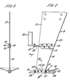
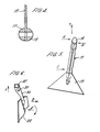
- the cultivating tool comprises a support member in the form of a frame 2 comprising typical longitudinal members 3 and 4 and typical transverse members 5 and 6.
- the frame 2 is mounted in use on the rear of a tractor by means of a hitch frame 1 providing the usual three point mounting.
- a bracket 7 on each side is mounted between the transverse members.
- a tine 8 is secured to each bracket 7 by bolts 9, 10.
- Each tine 8 comprises a laterally narrow and flexible leg 25 in two parts, typically of steel, extending downwardly and slightly forwardly from the frame.
- An elongate foot 11 having generally parallel sides is attached to the lower end of the leg by pins 22.
- the leg 25 is constructed from thin sections 12, 13 joined together by plates 14, held each side of each section by bolts 15. Attached to one of the plates 14 is a forwardly extending first bracket 30 which is located, in use, just above soil surface level. The forward end of this bracket is pivotally connected on a vertical axis by a bolt 31 to a downwardly extending second bracket 32 rigidly attached to the frame 2.
- the brackets 30, 32 and bolt 31 form a guide device to stabilise the leg and therefore the foot.
- the foot 11 consists of a hardened point 16, sides 17 and 18 and has attached at the rear end thereof a wing member 19 consisting of an upwardly inclined plate welded to a tongue 21 which is pivoted to members 17 and 18 by a bolt 27.
- Means for adjusting the inclination of the wing member is provided in the form of an adjustable cam 20 pivoted at 28 to the members 17 and 18 so as to support the wing member at a suitable angle: the cam has four straight edges each a different distance from the pivot giving a choice of four different inclinations of the wing memmber.
- One alternative inclination of wing member is shown in Figures 7 and 8 of the modified embodiment.
- the point 16 has its leading edge forwardly raked at an appropriate angle to the direction of motion.
- a tongue sandwiched between members 17 and 18; a bolt 29 passed through the members 17, 18 and this tongue has a nut threaded on its end for the purpose of clamping the members on the tongue, in the same manner as bolt 27 and its nut clamp the members on tongue 21.
- the thickness of the leg sections is generally not more than 20mm and a value of between 5mm and 15mm would be typical; 6mm and 12mm have been found successful in two examples.
- the ratio of the thickness of the leg sections to the free height of leg may be less than 1:40, less than 1:70 or even less than 1:100.
- the frame 2 In use the frame 2 is drawn through the ground by means of its hitch 1 attached to a tractor or towing vehicle. As the foot 11 engages with the ground, the leading edge of the point 16 produces a downward force which draws the implement down to its working depth (with the plates 14 just above the surface of the ground) until it is resisted by the tractor hitch system.
- the leading edge of the point 16 and the width and tilt of the wing section 19 together provide an up-thrust to the soil producing cracks which proceed upward towards the soil surface to create the required cultivation effect. Because the leg is of very thin section the volume of soil displaced upwards is minimal, the surface is left flat ; there.being no significant disturbance or ridge formation to interfere with subsequent surface cultivation operations, and the leg itself does not take much power in being drawn through the ground.
- the lateral flexibility of the leg allows the foot to deflect laterally away from the obstruction.
- the forms of the foot and the restraint applied to the leg by the forwardly extending pivoting bracket are such that a combination of restoring forces proportional to the magnitude of the deflection are set up to return the foot to its desired path parallel to the direction of motion of the tractor.
- Figure 5 shows the effect of a sideways force A, presented to the left-hand side of the point 16 by an obstruction as seen from above. Some details are omitted from this Figure for the sake of clarity.
- each side is in contact with the wall of soil formed by its path and thus any slight movement is immediately resisted by restoring forces B and C from the soil, force B resisting lateral movement and force C the yawing movement about a generally vertical axis. Should the forces B & C be insufficient on their own to correct the effect of the disturbing force A, the restraint applied to the leg by the forwardly extending pivoting bracket will also counteract the disturbing force.
- Figure 6 shows the effect of a sideways force D applied to the lower end of the leg seen from above, neither the division of the leg nor the foot being shown in this figure for the sake of clarity.
- the sideways force causes a sideways deflection of the leg 25 which, being restrained by the forwardly positioned pivot 31. is caused to be twisted in a sense to oppose the sideways movement.
- the twist produces an opposing force within the material which directs the foot back towards its desired path and, by virtue of the reaction between the ground and the twisted leg, causes the leg to "track" back to its original straight configuration.
- a pivotal connection may be substituted with a pivot axis either vertical or in a vertical plane orientated longitudinally of the direction of movement. This allows the tine greater freedom of movement and orientation in use, giving greater compensation for variations and obstacles in the soil.
- the foot may be pivotally mounted on the leg about a generally horizontal axis, allowing the foot to "float" in use according to the forces it experiences.
- the restraint of the forwardly placed pivot may be applied to the whole leg of the tine as described above, or alternatively to a separate front or shin section only, equivalent to shin section 23 described in prior U.K. Patent Application No. 8319273.
- the front or shin section would itself be flexibly mounted to the remainder of the tine, such as by a pivotal connection to the rear leg section (equivalent to 13' in the prior Application), to allow the shin section to turn about an axis parallel to its major axis.
Landscapes
- Life Sciences & Earth Sciences (AREA)
- Engineering & Computer Science (AREA)
- Mechanical Engineering (AREA)
- Soil Sciences (AREA)
- Environmental Sciences (AREA)
- Soil Working Implements (AREA)
- Quick-Acting Or Multi-Walled Pipe Joints (AREA)
Applications Claiming Priority (2)
| Application Number | Priority Date | Filing Date | Title |
|---|---|---|---|
| GB08418999A GB2162031A (en) | 1984-07-25 | 1984-07-25 | Subsoil cultivating tool |
| GB8418999 | 1984-07-25 |
Publications (2)
| Publication Number | Publication Date |
|---|---|
| EP0169285A2 true EP0169285A2 (de) | 1986-01-29 |
| EP0169285A3 EP0169285A3 (de) | 1986-06-25 |
Family
ID=10564451
Family Applications (1)
| Application Number | Title | Priority Date | Filing Date |
|---|---|---|---|
| EP84306716A Withdrawn EP0169285A3 (de) | 1984-07-25 | 1984-10-02 | Gerät zur Tiefenlockerung von Böden |
Country Status (4)
| Country | Link |
|---|---|
| EP (1) | EP0169285A3 (de) |
| DK (1) | DK474184A (de) |
| ES (1) | ES8600832A1 (de) |
| GB (1) | GB2162031A (de) |
Cited By (1)
| Publication number | Priority date | Publication date | Assignee | Title |
|---|---|---|---|---|
| US11490557B2 (en) * | 2017-02-13 | 2022-11-08 | Amazonen-Werke H. Dreyer SE & Co. KG | Sowing coulter with adjustable blades |
Family Cites Families (6)
| Publication number | Priority date | Publication date | Assignee | Title |
|---|---|---|---|---|
| US2703518A (en) * | 1953-10-27 | 1955-03-08 | Whitmore John Lester | Subsoil tool |
| GB1386454A (en) * | 1972-12-08 | 1975-03-05 | Parkin Eng Ltd | Subsoilers |
| FR2216894B1 (de) * | 1973-02-12 | 1976-05-14 | Boutin Georges | |
| FR2353212A1 (fr) * | 1976-06-04 | 1977-12-30 | Michel Marcel | Sous-soleuse vibrante |
| GB2061682B (en) * | 1979-10-24 | 1983-06-29 | Taylor K F | Agricultural appliances |
| GB2124064B (en) * | 1982-07-27 | 1985-08-07 | Bomford & Evershed Ltd | Subsoil cultivating tool |
-
1984
- 1984-07-25 GB GB08418999A patent/GB2162031A/en not_active Withdrawn
- 1984-10-02 EP EP84306716A patent/EP0169285A3/de not_active Withdrawn
- 1984-10-03 DK DK474184A patent/DK474184A/da not_active Application Discontinuation
- 1984-10-17 ES ES536813A patent/ES8600832A1/es not_active Expired
Cited By (1)
| Publication number | Priority date | Publication date | Assignee | Title |
|---|---|---|---|---|
| US11490557B2 (en) * | 2017-02-13 | 2022-11-08 | Amazonen-Werke H. Dreyer SE & Co. KG | Sowing coulter with adjustable blades |
Also Published As
| Publication number | Publication date |
|---|---|
| GB2162031A (en) | 1986-01-29 |
| ES536813A0 (es) | 1985-10-16 |
| DK474184A (da) | 1986-01-26 |
| ES8600832A1 (es) | 1985-10-16 |
| DK474184D0 (da) | 1984-10-03 |
| GB8418999D0 (en) | 1984-08-30 |
| EP0169285A3 (de) | 1986-06-25 |
Similar Documents
| Publication | Publication Date | Title |
|---|---|---|
| US4461355A (en) | Cultivator row unit with ridger/bedder implement | |
| US4208974A (en) | Seed drill having parallel guide means for the movable shank | |
| US3202222A (en) | Tillage machine | |
| EP0123561B1 (de) | Egge mit Federzinken für die Saatbettbereitung | |
| US5409068A (en) | Dual penetration combination sweep with ripper | |
| US8220559B2 (en) | Plough assembly for deep soil cultivation | |
| US4336844A (en) | Farm implement | |
| US4285404A (en) | Soil working machine with resilient support and trailing, rigid control arm | |
| EP0100186A2 (de) | Untergrundlockerer | |
| US5215150A (en) | Winged subsoil plow | |
| EP0169285A2 (de) | Gerät zur Tiefenlockerung von Böden | |
| EP0171861A1 (de) | Pflug | |
| GB2053634A (en) | Agricultural subsoiling tool | |
| US4781253A (en) | Shield for soil ripping implement | |
| US4328870A (en) | Plough for working of soil | |
| US3667550A (en) | Lister-chisel combination | |
| GB2100105A (en) | Cultivating implement | |
| US4505337A (en) | Plow jump mechanism | |
| US2712784A (en) | Jointer device for plow | |
| CZ292419B6 (cs) | Radlice, zejména pro pracovní rám držáku radlic | |
| JPH0458921B2 (de) | ||
| US4817727A (en) | Subtiller | |
| US4005757A (en) | Clamp shank device | |
| US4381823A (en) | Combination fertilizer applicator and tillage implement with adjustable sweep assemblies | |
| US2738601A (en) | Land-clearing plow attachment |
Legal Events
| Date | Code | Title | Description |
|---|---|---|---|
| PUAI | Public reference made under article 153(3) epc to a published international application that has entered the european phase |
Free format text: ORIGINAL CODE: 0009012 |
|
| AK | Designated contracting states |
Designated state(s): AT BE CH DE FR IT LI LU NL SE |
|
| PUAL | Search report despatched |
Free format text: ORIGINAL CODE: 0009013 |
|
| AK | Designated contracting states |
Kind code of ref document: A3 Designated state(s): AT BE CH DE FR IT LI LU NL SE |
|
| 17P | Request for examination filed |
Effective date: 19860717 |
|
| STAA | Information on the status of an ep patent application or granted ep patent |
Free format text: STATUS: THE APPLICATION HAS BEEN WITHDRAWN |
|
| 18W | Application withdrawn |
Withdrawal date: 19870803 |
|
| RIN1 | Information on inventor provided before grant (corrected) |
Inventor name: CUTLER, FREDERICK Inventor name: OSBORNE, RICHARD CHARLES Inventor name: FOX, JOHN VAUDREY |