EP0168926B1 - Method and apparatus for melt-lamination by co-extrusion - Google Patents
Method and apparatus for melt-lamination by co-extrusion Download PDFInfo
- Publication number
- EP0168926B1 EP0168926B1 EP85303537A EP85303537A EP0168926B1 EP 0168926 B1 EP0168926 B1 EP 0168926B1 EP 85303537 A EP85303537 A EP 85303537A EP 85303537 A EP85303537 A EP 85303537A EP 0168926 B1 EP0168926 B1 EP 0168926B1
- Authority
- EP
- European Patent Office
- Prior art keywords
- flow
- laminate
- die
- manifold
- melt
- Prior art date
- Legal status (The legal status is an assumption and is not a legal conclusion. Google has not performed a legal analysis and makes no representation as to the accuracy of the status listed.)
- Expired
Links
- 238000001125 extrusion Methods 0.000 title claims description 20
- 238000000034 method Methods 0.000 title claims description 11
- 238000003475 lamination Methods 0.000 title description 5
- 239000012815 thermoplastic material Substances 0.000 claims description 13
- 230000000694 effects Effects 0.000 claims description 11
- 229920001169 thermoplastic Polymers 0.000 claims description 10
- 239000004416 thermosoftening plastic Substances 0.000 claims description 10
- 239000011347 resin Substances 0.000 description 6
- 229920005989 resin Polymers 0.000 description 6
- 238000011144 upstream manufacturing Methods 0.000 description 4
- 230000007547 defect Effects 0.000 description 2
- 238000003754 machining Methods 0.000 description 1
- 239000000463 material Substances 0.000 description 1
- 239000000155 melt Substances 0.000 description 1
- 238000000518 rheometry Methods 0.000 description 1
- 230000002195 synergetic effect Effects 0.000 description 1
Images

Classifications
-
- B—PERFORMING OPERATIONS; TRANSPORTING
- B29—WORKING OF PLASTICS; WORKING OF SUBSTANCES IN A PLASTIC STATE IN GENERAL
- B29C—SHAPING OR JOINING OF PLASTICS; SHAPING OF MATERIAL IN A PLASTIC STATE, NOT OTHERWISE PROVIDED FOR; AFTER-TREATMENT OF THE SHAPED PRODUCTS, e.g. REPAIRING
- B29C48/00—Extrusion moulding, i.e. expressing the moulding material through a die or nozzle which imparts the desired form; Apparatus therefor
- B29C48/25—Component parts, details or accessories; Auxiliary operations
- B29C48/30—Extrusion nozzles or dies
- B29C48/305—Extrusion nozzles or dies having a wide opening, e.g. for forming sheets
- B29C48/307—Extrusion nozzles or dies having a wide opening, e.g. for forming sheets specially adapted for bringing together components, e.g. melts within the die
-
- B—PERFORMING OPERATIONS; TRANSPORTING
- B29—WORKING OF PLASTICS; WORKING OF SUBSTANCES IN A PLASTIC STATE IN GENERAL
- B29C—SHAPING OR JOINING OF PLASTICS; SHAPING OF MATERIAL IN A PLASTIC STATE, NOT OTHERWISE PROVIDED FOR; AFTER-TREATMENT OF THE SHAPED PRODUCTS, e.g. REPAIRING
- B29C48/00—Extrusion moulding, i.e. expressing the moulding material through a die or nozzle which imparts the desired form; Apparatus therefor
- B29C48/03—Extrusion moulding, i.e. expressing the moulding material through a die or nozzle which imparts the desired form; Apparatus therefor characterised by the shape of the extruded material at extrusion
- B29C48/07—Flat, e.g. panels
- B29C48/08—Flat, e.g. panels flexible, e.g. films
-
- B—PERFORMING OPERATIONS; TRANSPORTING
- B29—WORKING OF PLASTICS; WORKING OF SUBSTANCES IN A PLASTIC STATE IN GENERAL
- B29C—SHAPING OR JOINING OF PLASTICS; SHAPING OF MATERIAL IN A PLASTIC STATE, NOT OTHERWISE PROVIDED FOR; AFTER-TREATMENT OF THE SHAPED PRODUCTS, e.g. REPAIRING
- B29C48/00—Extrusion moulding, i.e. expressing the moulding material through a die or nozzle which imparts the desired form; Apparatus therefor
- B29C48/16—Articles comprising two or more components, e.g. co-extruded layers
- B29C48/18—Articles comprising two or more components, e.g. co-extruded layers the components being layers
- B29C48/21—Articles comprising two or more components, e.g. co-extruded layers the components being layers the layers being joined at their surfaces
-
- B—PERFORMING OPERATIONS; TRANSPORTING
- B29—WORKING OF PLASTICS; WORKING OF SUBSTANCES IN A PLASTIC STATE IN GENERAL
- B29C—SHAPING OR JOINING OF PLASTICS; SHAPING OF MATERIAL IN A PLASTIC STATE, NOT OTHERWISE PROVIDED FOR; AFTER-TREATMENT OF THE SHAPED PRODUCTS, e.g. REPAIRING
- B29C48/00—Extrusion moulding, i.e. expressing the moulding material through a die or nozzle which imparts the desired form; Apparatus therefor
- B29C48/03—Extrusion moulding, i.e. expressing the moulding material through a die or nozzle which imparts the desired form; Apparatus therefor characterised by the shape of the extruded material at extrusion
- B29C48/07—Flat, e.g. panels
Definitions
- the present invention relates to the melt-lamination of thermoplastic materials. More specifically, this invention primarily relates to forming a laminate from resins of dissimilar flow properties, using a combining adaptor in combination with a die.
- melt-lamination apparatus including a combining adaptor, a die and a connecting duct, which in cross-section is typically rectangular in shape.
- Flow channels converge in the adaptor, as a result of which there is a confluence of the molten resin streams which flow through the flow channels, to form a melt-laminate.
- the layered melt stream exits from the combining adaptor, passes through the connecting duct and flows into the die, typically a single manifold die.
- the melt-laminate diverges at a locus of divergence and transverse flow takes place over the length of the manifold.
- the layered melt stream leaving the manifold is wider than the stream entering the manifold. This wider melt-laminate flows through an exit channel and exits from the die.
- each layer of the laminate formed thereby exhibits the curtaining effect.
- the curtaining effect is a well known defect in the layers of a thermoplastic laminate. It is characterized by a pattern in the individual layers that is particularly apparent when the layers are pigmented.
- a combining adaptor having an adjustable divider provided between any two of the flow channels thereof.
- Each flow channel includes a back pressure cavity and a flow restriction channel located between the back pressure cavity and the point of convergence of the flow channels.
- This combining adaptor provides for adjustment of flow restriction channel width by manipulation ofthe adjustable divider.
- Extrusion apparatus includes a die comprising a manifold chamber within which there is a locus of divergence, and a combining adaptor comprising a first flow channel.
- the extrusion apparatus includes a second flow channel. Between these flow channels, a flow divider is disposed. The flow channels converge at a point of confluence to form a combined flow passage which connects to the die manifold chamber.
- the combining adaptor is inserted into a cavity of the die.
- the locus of divergence is situated in the proximity of the point of confluence such that profiling of the melt-laminate formed at the point of confluence is not essential to produce, from thermoplastic streams of dissimilar flow properties, a laminated sheet each layer of which is of substantially uniform thickness. Furthermore, the curtaining effect is lessened in the layers of the laminate.
- a process according to the present invention produces a laminate without profiling of the layered melt stream.
- This process includes the step of forming the layered melt stream in the proximity of a locus at which the stream is caused to diverge and thereby undergo a transverse flow such that profiling of the layered melt stream is not essential to produce, from molten thermoplastic streams of dissimilar flow properties, a laminated sheet having layers each of substantially uniform thickness.
- a further result of this process is that the curtaining effect is reduced in the layers of the laminate.
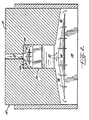
- FIGURE 1 is a cross-sectional view at mid- center of a preferred extrusion apparatus in accordance with the present invention.
- FIGURE 2 is a view of the extrusion apparatus of FIGURE 1, taken along the line 2-2 in FIGURE 1, which shows the locus of divergence 48.
- the present invention is directed to a novel extrusion apparatus and to a unique process for the melt-lamination of thermoplastic materials. More particularly, a longfelt need met by my invention is that it makes it possible to use a combining adaptor and die to form a laminate each layer of which is of substantially uniform thickness, without the necessity of profiling. Specifically, it is intended that this invention be primarily used for forming a laminate from thermoplastic materials of dissimilar flow properties.
- melt laminate By the term “dissimilar flow properties" as used in this description of my invention, I mean that the streams of thermoplastic materials converged to form a melt laminate have flow properties that are so unlike, that one skilled in the extrusion art would profile the melt-laminate formed, in order to produce a laminate having layers each of substantially uni ' - form thickness. Moreover, this invention lessens the curtaining effect, a well known defect.
- Extrusion apparatus 10 includes a die 12 and a combining adaptor 14.
- the die has a cavity for receiving the adaptor, in which the adaptor is inserted.
- Apparatus 10 provides for the passage of a thermoplastic stream through each of flow channels 16 and 18, and for convergence of these streams at a point of confluence 20 of the flow channels. At the point of confluence, a combined flow passage 22 is formed, and convergence of the molten streams produces a melt-laminate.
- a section of flow channel 16 and of flow channel 18 passes through combining adaptor 14. Alternatively, for purposes of illustration, the adaptor could cooperate with a longitudinal wall of the die cavity to form a portion of flow channel 16.
- Each flow channel preferably includes a manifold or manifold chamber, shown as 26 and 28, in which transverse flow of the molten stream passing therethrough, occurs. As a result, each stream is longitudinally distributed over the entire manifold length.
- Each flow channel also preferably includes a flow restriction channel, shown as 30 and 32, through which the stream passes from the manifold to point of confluence 20.
- the restriction channels are tapered, when viewed in cross-section, in the direction of the point of flow channel confluence.
- the manifolds are coat-hanger type manifolds, that is, they have a cross-sectional area that diminishes from the center to each end thereof.
- the manifolds may be of constant or variable cross-section depending upon, for example, individual thermoplastic material requirements.
- a manifold having a constant cross-section from end to end is a keyhole type manifold.
- the size of a manifold in terms of its cross-sectional area is determined by the required thermoplastic material throughput. More specifically, a greater cross-sectional area is required in order for a greater volume of material to pass through, in a given period of time.
- Each flow restriction channel has a cross-sectional area that is smaller than the area of any cross-section of the upstream manifold.
- Flow restriction channel 30 is formed by a longitudinal interior wall 34 of the combining adaptor and a longitudinal wall 36 of a point portion 38 of a divider or vane blade 40.
- Flow restriction channel 32 is formed by a longitudinal wall 42 of point portion 38 and a longitudinal interior wall 24 of the combining adaptor.
- Vane blade 40 Situated between flow channels 16 and 18 is vane blade 40.
- Vane blade 40 has a head portion 43 and point portion 38. As the vane blade pivots in a bearing (not shown), point portion 38 moves laterally, thereby defining the cross-sectional areas of the two flow restriction channels. Point portion 38 has a tip end 44.
- Combined flow passage 22 which is typically rectangular but may be square, includes a manifold or manifold chamber 46.
- a locus of divergence 48 within the manifold is a locus of divergence 48, where the layered melt stream formed at point of confluence 20 is caused to diverge. This divergence results in transverse flow over the manifold length.
- An important feature of apparatus 10 is that the point of confluence of flow channels 16 and 18 is in the proximity of the locus of divergence.
- point of confluence 20 is as close as possible to manifold 46, say 12 up to 25 mm upstream from the manifold.
- point of confluence 20 could be within the manifold and just upstream, say 12 up to 25 mm above locus of divergence 48.
- Manifold 46 is preferably of the coat-hanger type. However, the manifold could be of constant cross-section, The size of the manifold is determined by the required resin throughput.
- melt-laminate flows through an exit channel 50, Finally, it exits apparatus 10 at an opening 52.
- a further advantage of my preferred extrusion apparatus is that combining adaptor 14 is removable from the die, and may be replaced with an interchangeable adaptor in order to provide apparatus 10 with flow channels having a configuration precisely suited to the viscosities of the resins to be passed through the flow channels. This feature avoids the necessity of otherwise using a completely different extrusion apparatus having flow channels of the needed configuration.
- My invention can be employed with an existing die body, or with a new die body produced with a cavity therein for receiving the combining adaptor.
- An existing conventional single manifold die could be subjected to, for example, electro-discharge machining to form the cavity.
- a second flow channel could then be drilled in the die that would combine with the flow channel passing through the combining adaptor to form one of the flow passages converging at the point of confluence.
- the existing flow passage leading to the manifold of the die could be plugged and two flowchannels drilled in the die thatwouId combine with the two flow channels passing through the combining adaptor.
- the apparatus shown in Figures 1 and 2 is illustrative of the structure of an extrusion apparatus produced using this alternative method.
- An extrusion apparatus in accordance with my invention can be used to form, for example, a three, four, five, seven or nine layer laminate. These multilayer laminates are achievable by the use of a multi- manifold die in combination with one or more combining adaptor inserts.
- molten thermoplastic streams enter flow channels 16 and 18, are spread transversely in manifolds 26 and 28, are reduced in cross-sectional area in flow restriction channels 30 and 32, and converge at point of confluence 20, to form a layered melt stream.
- the melt-laminate flows through combined flow passage 22, and enters manifold 46, in which it is caused to diverge. As a result, transverse flow takes place over the manifold length.
- the layered melt stream finally exits from die 12 after passing through exit channel 50.
- the laminate produced has layers each of substantially uniform thickness without profiling of the melt-laminate, and exhibits a lessened curtaining effect.
- an essential step is as follows. A melt-laminate is formed from the molten thermoplastics in the proximity of a locus at which the melt-laminate is caused to diverge. As a result, profiling of the melt-laminate is not essential to produce the laminate, which has layers each of substantially uniform thickness. Afurther result of this process is that the curtaining effect is reduced in the layers of the laminate.
Landscapes
- Engineering & Computer Science (AREA)
- Mechanical Engineering (AREA)
- Manufacturing & Machinery (AREA)
- Extrusion Moulding Of Plastics Or The Like (AREA)
Description
- The present invention relates to the melt-lamination of thermoplastic materials. More specifically, this invention primarily relates to forming a laminate from resins of dissimilar flow properties, using a combining adaptor in combination with a die.
- One approach to the melt-lamination of thermoplastic materials is to use an extrusion apparatus including a combining adaptor, a die and a connecting duct, which in cross-section is typically rectangular in shape. Flow channels converge in the adaptor, as a result of which there is a confluence of the molten resin streams which flow through the flow channels, to form a melt-laminate. The layered melt stream exits from the combining adaptor, passes through the connecting duct and flows into the die, typically a single manifold die. In the die manifold, the melt-laminate diverges at a locus of divergence and transverse flow takes place over the length of the manifold. Hence, the layered melt stream leaving the manifold is wider than the stream entering the manifold. This wider melt-laminate flows through an exit channel and exits from the die.
- A problem with this type of apparatus is that a laminate formed from thermoplastic materials of dissimilar flow properties will have layers of non-uniform thickness. A.A. Khan and C.D. Han, Transactions of the Society of Rheology, vol. 20(4), pp. 595-621 (1976), report investigative studies relating to this problem. Figure 7 of this publication shows that the layers of a melt-laminate become increasingly non-uniform as the melt-laminate progressively flows through a rectangular duct. Furthermore, passing the layered melt stream through a die manifold additionally promotes layer non-uniformity.
- A further problem with this type of apparatus is that each layer of the laminate formed thereby exhibits the curtaining effect. The curtaining effect is a well known defect in the layers of a thermoplastic laminate. It is characterized by a pattern in the individual layers that is particularly apparent when the layers are pigmented.
- An extrusion apparatus is known in which the combining adaptor is connected directly to a die. This type of apparatus, which is exemplified by U.S. Patent 3,761,211 to Parkinson, advantageously lacks the connecting duct.
- However, it does not provide a solution to either of these problems.
- Also known in the prior art, as illustrated by my U.S. Patents 4,152,387 and 4,197,069, is a combining adaptor having an adjustable divider provided between any two of the flow channels thereof. Each flow channel includes a back pressure cavity and a flow restriction channel located between the back pressure cavity and the point of convergence of the flow channels. This combining adaptor provides for adjustment of flow restriction channel width by manipulation ofthe adjustable divider. The layers of a laminate made by use of this adaptor in combination with a conventional single manifold die, exhibit the curtaining effect.
- One solution to the problem of layer non-uniformity has been to profile the melt-laminate, that is, to transform the cross-sectional configuration of each stream of the melt-laminate from a rectangular configuration to a shape that is changed back to the original rectangular configuration as the melt-laminate passes from the point at which it is formed, through the die manifold. Profiling has been found to produce a laminate with layers each of uniform thickness, from thermoplastic materials of dissimilar flow properties. However, a drawback with profiling is that experimentation is usually required to determine the precise shape to which it is necessary to intentionally alter the cross-sectional configuration of the layered melt stream. Experimentation is, of course, expensive in terms of both time and money:
- From the preceding discussion, it is clear that there is a need for an extrusion apparatus that includes a combining adaptor and a die, that will produce a laminate with layers each of substantially uniform thickness from thermoplastic materials of dissimilar flow properties without profiling of the melt-laminate formed from these thermoplastic materials. Such an improved apparatus would be especially remarkable if it were capable of handling resins of varying viscosities, merely by removal of and replacement of a component thereof with an interchangeable component exactly configured for specific resin viscosities. Moreover, such an improved apparatus would provide an even greater contribution to the art if it lessened the curtaining effect. Such an apparatus would make possible an improved process for the melt-lamination of thermoplastic materials.
- Extrusion apparatus according to the present invention includes a die comprising a manifold chamber within which there is a locus of divergence, and a combining adaptor comprising a first flow channel. The extrusion apparatus includes a second flow channel. Between these flow channels, a flow divider is disposed. The flow channels converge at a point of confluence to form a combined flow passage which connects to the die manifold chamber.
- The combining adaptor is inserted into a cavity of the die. The locus of divergence is situated in the proximity of the point of confluence such that profiling of the melt-laminate formed at the point of confluence is not essential to produce, from thermoplastic streams of dissimilar flow properties, a laminated sheet each layer of which is of substantially uniform thickness. Furthermore, the curtaining effect is lessened in the layers of the laminate.
- A process according to the present invention produces a laminate without profiling of the layered melt stream. This process includes the step of forming the layered melt stream in the proximity of a locus at which the stream is caused to diverge and thereby undergo a transverse flow such that profiling of the layered melt stream is not essential to produce, from molten thermoplastic streams of dissimilar flow properties, a laminated sheet having layers each of substantially uniform thickness. A further result of this process is that the curtaining effect is reduced in the layers of the laminate.
- Reference is now made to the accompanying drawing, which forms a part of the specification of the present invention, and which depicts a preferred embodiment of an extrusion apparatus in accordance with the present invention.
- FIGURE 1 is a cross-sectional view at mid- center of a preferred extrusion apparatus in accordance with the present invention; and
- FIGURE 2 is a view of the extrusion apparatus of FIGURE 1, taken along the line 2-2 in FIGURE 1, which shows the locus of
divergence 48. - As explained, the present invention is directed to a novel extrusion apparatus and to a unique process for the melt-lamination of thermoplastic materials. More particularly, a longfelt need met by my invention is that it makes it possible to use a combining adaptor and die to form a laminate each layer of which is of substantially uniform thickness, without the necessity of profiling. Specifically, it is intended that this invention be primarily used for forming a laminate from thermoplastic materials of dissimilar flow properties. By the term "dissimilar flow properties" as used in this description of my invention, I mean that the streams of thermoplastic materials converged to form a melt laminate have flow properties that are so unlike, that one skilled in the extrusion art would profile the melt-laminate formed, in order to produce a laminate having layers each of substantially uni'- form thickness. Moreover, this invention lessens the curtaining effect, a well known defect.
- Referring to Figures 1 and 2, a preferred
extrusion apparatus 10 in accordance with the present invention is shown.Extrusion apparatus 10 includes a die 12 and a combining adaptor 14. The die has a cavity for receiving the adaptor, in which the adaptor is inserted. -
Apparatus 10 provides for the passage of a thermoplastic stream through each of flow channels 16 and 18, and for convergence of these streams at a point of confluence 20 of the flow channels. At the point of confluence, a combined flow passage 22 is formed, and convergence of the molten streams produces a melt-laminate. A section of flow channel 16 and of flow channel 18 passes through combining adaptor 14. Alternatively, for purposes of illustration, the adaptor could cooperate with a longitudinal wall of the die cavity to form a portion of flow channel 16. - Each flow channel preferably includes a manifold or manifold chamber, shown as 26 and 28, in which transverse flow of the molten stream passing therethrough, occurs. As a result, each stream is longitudinally distributed over the entire manifold length. Each flow channel also preferably includes a flow restriction channel, shown as 30 and 32, through which the stream passes from the manifold to point of confluence 20. The restriction channels are tapered, when viewed in cross-section, in the direction of the point of flow channel confluence.
- The manifolds are coat-hanger type manifolds, that is, they have a cross-sectional area that diminishes from the center to each end thereof. The manifolds may be of constant or variable cross-section depending upon, for example, individual thermoplastic material requirements. A manifold having a constant cross-section from end to end is a keyhole type manifold.
- The size of a manifold in terms of its cross-sectional area is determined by the required thermoplastic material throughput. More specifically, a greater cross-sectional area is required in order for a greater volume of material to pass through, in a given period of time.
- Each flow restriction channel has a cross-sectional area that is smaller than the area of any cross-section of the upstream manifold. Flow restriction channel 30 is formed by a longitudinal interior wall 34 of the combining adaptor and a longitudinal wall 36 of a point portion 38 of a divider or vane blade 40. Flow restriction channel 32 is formed by a longitudinal wall 42 of point portion 38 and a longitudinal interior wall 24 of the combining adaptor.
- Situated between flow channels 16 and 18 is vane blade 40. Vane blade 40 has a head portion 43 and point portion 38. As the vane blade pivots in a bearing (not shown), point portion 38 moves laterally, thereby defining the cross-sectional areas of the two flow restriction channels. Point portion 38 has a tip end 44.
- Between the upstream manifold and the flow restriction channel in each flow channel are a pressure compensating restriction channel and an expansion chamber. These features are not essential to this invention, and are described with particularity in European Patent Application No. 85302615.1, to which reference may be made for any relevant illustration of this description. Furthermore, as described in that application, vane blade 40 is self-adjusting, but again this is not essential to the present invention.
- Combined flow passage 22, which is typically rectangular but may be square, includes a manifold or
manifold chamber 46. Referring more particularly to Figure 2, within the manifold is a locus ofdivergence 48, where the layered melt stream formed at point of confluence 20 is caused to diverge. This divergence results in transverse flow over the manifold length. An important feature ofapparatus 10 is that the point of confluence of flow channels 16 and 18 is in the proximity of the locus of divergence. Hence, point of confluence 20 is as close as possible tomanifold 46, say 12 up to 25 mm upstream from the manifold. Alternatively, point of confluence 20 could be within the manifold and just upstream, say 12 up to 25 mm above locus ofdivergence 48. This latter location is achieved by tip end 44 of the point portion of the vane blade being extended intomanifold 46. The result of this characteristic of my invention is that inclusion of a means for profiling the layered melt stream is not necessary, in order to obtain a laminate each layer of which is of substantially uniform thickness, Moreover, another result of this characteristic is that the curtaining effect is lessened in the layers of the laminate. Accordingly, by the point of confluence of the flow channels being situated in the proximity of the locus of divergence, a synergistic effect results. -
Manifold 46 is preferably of the coat-hanger type. However, the manifold could be of constant cross-section, The size of the manifold is determined by the required resin throughput. - After leaving
manifold 46, the melt-laminate flows through an exit channel 50, Finally, it exitsapparatus 10 at an opening 52. - A further advantage of my preferred extrusion apparatus is that combining adaptor 14 is removable from the die, and may be replaced with an interchangeable adaptor in order to provide
apparatus 10 with flow channels having a configuration precisely suited to the viscosities of the resins to be passed through the flow channels. This feature avoids the necessity of otherwise using a completely different extrusion apparatus having flow channels of the needed configuration. - My invention can be employed with an existing die body, or with a new die body produced with a cavity therein for receiving the combining adaptor. An existing conventional single manifold die could be subjected to, for example, electro-discharge machining to form the cavity. A second flow channel could then be drilled in the die that would combine with the flow channel passing through the combining adaptor to form one of the flow passages converging at the point of confluence. Alternatively, the existing flow passage leading to the manifold of the die could be plugged and two flowchannels drilled in the die thatwouId combine with the two flow channels passing through the combining adaptor. The apparatus shown in Figures 1 and 2 is illustrative of the structure of an extrusion apparatus produced using this alternative method.
- An extrusion apparatus in accordance with my invention can be used to form, for example, a three, four, five, seven or nine layer laminate. These multilayer laminates are achievable by the use of a multi- manifold die in combination with one or more combining adaptor inserts.
- In operation, molten thermoplastic streams enter flow channels 16 and 18, are spread transversely in manifolds 26 and 28, are reduced in cross-sectional area in flow restriction channels 30 and 32, and converge at point of confluence 20, to form a layered melt stream. The melt-laminate flows through combined flow passage 22, and enters
manifold 46, in which it is caused to diverge. As a result, transverse flow takes place over the manifold length. The layered melt stream finally exits from die 12 after passing through exit channel 50. The laminate produced has layers each of substantially uniform thickness without profiling of the melt-laminate, and exhibits a lessened curtaining effect. - In my process for making a laminate with layers each of substantially uniform thickness from molten thermoplastics of dissimilar flow properties, an essential step is as follows. A melt-laminate is formed from the molten thermoplastics in the proximity of a locus at which the melt-laminate is caused to diverge. As a result, profiling of the melt-laminate is not essential to produce the laminate, which has layers each of substantially uniform thickness. Afurther result of this process is that the curtaining effect is reduced in the layers of the laminate.
Claims (5)
wherein a flow divider (40) is disposed between a flow channel (16) and the flow channel (18); and wherein the flow channels (16, 18) converge at a point of confluence (20) to form a flow passage (22) which connects to the die manifold chamber (46);
characterised in that the combining adaptor (14) is inserted in a cavity of the die (12), and in that the locus of divergence (48) is in the proximity of the point of confluence (20) such that profiling of a layered melt stream formed at the point of confluence (20) is not essential to produce, from thermoplastic streams of dissimilar flow properties, a laminated sheet each layer of which is of substantially uniform thickness.
Applications Claiming Priority (2)
| Application Number | Priority Date | Filing Date | Title |
|---|---|---|---|
| US06/612,307 US4619802A (en) | 1984-05-21 | 1984-05-21 | Die with combining adaptor insert and melt-lamination process |
| US612307 | 1984-05-21 |
Publications (3)
| Publication Number | Publication Date |
|---|---|
| EP0168926A2 EP0168926A2 (en) | 1986-01-22 |
| EP0168926A3 EP0168926A3 (en) | 1986-11-20 |
| EP0168926B1 true EP0168926B1 (en) | 1989-07-26 |
Family
ID=24452626
Family Applications (1)
| Application Number | Title | Priority Date | Filing Date |
|---|---|---|---|
| EP85303537A Expired EP0168926B1 (en) | 1984-05-21 | 1985-05-20 | Method and apparatus for melt-lamination by co-extrusion |
Country Status (7)
| Country | Link |
|---|---|
| US (1) | US4619802A (en) |
| EP (1) | EP0168926B1 (en) |
| KR (1) | KR890002684B1 (en) |
| BR (1) | BR8502369A (en) |
| CA (1) | CA1240112A (en) |
| DE (1) | DE3571781D1 (en) |
| MX (1) | MX165026B (en) |
Families Citing this family (34)
| Publication number | Priority date | Publication date | Assignee | Title |
|---|---|---|---|---|
| US4731004A (en) * | 1984-10-12 | 1988-03-15 | Princeton Packaging, Inc. | Side-by-side co-extrusion of film using multiple materials |
| US4708615A (en) * | 1986-10-29 | 1987-11-24 | The Dow Chemical Company | Low pressure drop, modular coextrusion feedblock |
| US4780258A (en) * | 1987-07-17 | 1988-10-25 | P.C.E. Corp. | Coextruded laminate having barrier layers |
| US4892700A (en) * | 1987-10-07 | 1990-01-09 | Polycast Technology Corporation | Process for making multilayered, formable laminates |
| US4892473A (en) * | 1988-12-22 | 1990-01-09 | Bridgestone/Firestone, Inc. | Head for extrusion of elastomeric contour innerliner |
| DE3920774A1 (en) * | 1989-06-24 | 1991-01-10 | Ver Glaswerke Gmbh | CASTING DEVICE FOR CASTING TRANSPARENT PLASTIC LAYERS WITH A COLORED FILTER TAPE |
| DE3929002A1 (en) * | 1989-09-01 | 1991-03-14 | Schmidt Erwepa Maschf | DEVICE FOR EXTRUDING PLASTIC MULTILAYER FILMS OR PANELS |
| US5281380A (en) * | 1990-07-12 | 1994-01-25 | Bando Chemical Industries, Ltd. | Method for manufacturing fiber reinforced elastic sheet, apparatus for manufacturing the same and mold to be used |
| US5589122A (en) * | 1991-10-01 | 1996-12-31 | Minnesota Mining And Manufacturing Company | Method of making double-sided pressure-sensitive adhesive tape |
| US5375990A (en) * | 1992-09-10 | 1994-12-27 | Extrusion Dies, Inc. | Feed block for coextrusion apparatus |
| DE9216920U1 (en) * | 1992-10-13 | 1994-02-24 | Windmöller & Hölscher, 49525 Lengerich | Extrusion tool for the extrusion of melt hoses |
| US5320679A (en) * | 1993-07-28 | 1994-06-14 | Eastman Kodak Company | Coating hopper with criss-cross flow circuit |
| DE69414515T2 (en) * | 1993-09-07 | 1999-04-29 | Extrusion Dies, Inc., Chippewa Falls, Wis. | Device for the extrusion of thermoplastic materials |
| US5329964A (en) * | 1993-09-09 | 1994-07-19 | Eastman Kodak Company | Criss-cross hopper including non-contacting inserts |
| US5516474A (en) * | 1993-11-24 | 1996-05-14 | The Cloeren Company | Thermally distinct layer coextrusion |
| DE4410859C2 (en) * | 1994-03-29 | 1996-01-25 | Kloeckner Er We Pa Gmbh | Feedblock for wide slot nozzles |
| US5516273A (en) * | 1994-09-06 | 1996-05-14 | Minnesota Mining And Manufacturing Company | Die for extruding a fluid stream |
| WO1996020088A1 (en) | 1994-12-27 | 1996-07-04 | Ford Motor Company | Method and apparatus for dispensing viscous material |
| US5750159A (en) * | 1996-06-24 | 1998-05-12 | Minnesota Mining & Manufacturing Company | Die for extruding one or more fluid streams |
| US5851566A (en) * | 1996-07-02 | 1998-12-22 | Avery Dennison | Applicator die |
| US5843230A (en) * | 1996-07-02 | 1998-12-01 | Avery Dennison | Sealing system for improved applicator die |
| US5780067A (en) * | 1996-09-10 | 1998-07-14 | Extrusion Dies, Inc. | Adjustable coextrusion feedblock |
| JPH10335362A (en) * | 1997-06-03 | 1998-12-18 | Yazaki Corp | Structure of insert pin |
| US6109592A (en) * | 1997-06-16 | 2000-08-29 | Extrusion Dies, Inc. | Flow control device and apparatus for mounting same |
| US6206680B1 (en) | 1998-03-17 | 2001-03-27 | Extrusion Dies, Inc. | Extrusion die membrane |
| US6367776B1 (en) | 1999-04-21 | 2002-04-09 | Extrusion Dies, Inc. | Flow control device and apparatus for mounting same |
| US6352424B1 (en) | 1999-12-30 | 2002-03-05 | Extrusion Dies, Inc. | Extrusion die membrane assembly |
| US6626206B1 (en) | 2000-01-20 | 2003-09-30 | Extrusion Dies, Inc. | Feedblock for adjusting the dimensions of a set of co-extruded layers of a multi-layer sheet |
| US6821106B1 (en) * | 2003-06-24 | 2004-11-23 | The Goodyear Tire & Rubber Company | Roller die preformer for wide extrusions |
| RU2350465C2 (en) * | 2005-07-11 | 2009-03-27 | Герман Гаджиахмедович Рамалданов | Flat-slit two-chamber head |
| CN101511563B (en) * | 2006-09-06 | 2012-10-10 | 普瑞曼聚合物株式会社 | Injection molding metal mold and shaped article |
| US8002535B2 (en) * | 2009-05-14 | 2011-08-23 | The Goodyear Tire & Rubber Co. | Method and assembly for extruding a rubber compound |
| KR102252057B1 (en) | 2013-02-21 | 2021-05-17 | 쓰리엠 이노베이티브 프로퍼티즈 컴파니 | Self-adhering tape comprising multilayers of polyolefin polymer materials and method |
| US10282583B2 (en) | 2015-12-22 | 2019-05-07 | Gemalto Sa | Fingerprint imaging systems comprising self-wetting adhesive, films and methods |
Family Cites Families (16)
| Publication number | Priority date | Publication date | Assignee | Title |
|---|---|---|---|---|
| US3587281A (en) * | 1961-10-02 | 1971-06-28 | Jerome H Lemelson | Extrusion die apparatus |
| US3223761A (en) * | 1962-04-30 | 1965-12-14 | Union Carbide Corp | Melt extrusion of multi-wall plastic tubing |
| US3397428A (en) * | 1964-08-14 | 1968-08-20 | Dow Chemical Co | Apparatus for the preparation of thermoplastic resinous composite articles |
| US3320636A (en) * | 1965-09-20 | 1967-05-23 | Nat Distillers Chem Corp | Multi-ply flow diverter for thermoplastic materials |
| US3825383A (en) * | 1969-08-12 | 1974-07-23 | E Tonn | Apparatus for producing multilaminated film |
| SU397357A1 (en) * | 1971-05-12 | 1973-09-17 | PLATFLOWER EXTRUDER HEAD | |
| US3743459A (en) * | 1971-05-19 | 1973-07-03 | Dow Chemical Co | Apparatus for coextrusion of multilayer sheet or films |
| US3761211A (en) * | 1972-01-17 | 1973-09-25 | Crompton & Knowles Corp | Multi-layer extrusion apparatus |
| US4197069A (en) * | 1976-05-21 | 1980-04-08 | Peter Cloeren | Variable thickness extrusion die |
| US4152387A (en) * | 1976-05-21 | 1979-05-01 | Peter Cloeren | Method for forming multi-layer laminates |
| US4171195A (en) * | 1977-11-17 | 1979-10-16 | Scientific Process & Research, Inc. | Cross-head die with volumetric flow compensation means |
| US4189292A (en) * | 1978-03-14 | 1980-02-19 | Hubert Gaillard | Extruding head for making reticulated seamless tubes |
| JPS591180B2 (en) * | 1978-11-07 | 1984-01-10 | 東燃石油化学株式会社 | coat hanger die |
| US4240782A (en) * | 1979-10-17 | 1980-12-23 | The Gates Rubber Company | Extruder head for making elastomer-fiber composite hose |
| DE3043204A1 (en) * | 1980-11-15 | 1982-07-01 | Mauser-Werke GmbH, 5040 Brühl | OUTLET NOZZLE |
| JPS58209529A (en) * | 1982-06-01 | 1983-12-06 | Toa Nenryo Kogyo Kk | Die for straight manifold type coat hanger |
-
1984
- 1984-05-21 US US06/612,307 patent/US4619802A/en not_active Expired - Lifetime
- 1984-08-28 KR KR1019840005234A patent/KR890002684B1/en not_active IP Right Cessation
-
1985
- 1985-05-13 MX MX205277A patent/MX165026B/en unknown
- 1985-05-14 CA CA000481438A patent/CA1240112A/en not_active Expired
- 1985-05-20 DE DE8585303537T patent/DE3571781D1/en not_active Expired
- 1985-05-20 BR BR8502369A patent/BR8502369A/en not_active IP Right Cessation
- 1985-05-20 EP EP85303537A patent/EP0168926B1/en not_active Expired
Also Published As
| Publication number | Publication date |
|---|---|
| US4619802A (en) | 1986-10-28 |
| MX165026B (en) | 1992-10-14 |
| KR850008129A (en) | 1985-12-13 |
| CA1240112A (en) | 1988-08-09 |
| DE3571781D1 (en) | 1989-08-31 |
| KR890002684B1 (en) | 1989-07-24 |
| BR8502369A (en) | 1986-01-21 |
| EP0168926A2 (en) | 1986-01-22 |
| EP0168926A3 (en) | 1986-11-20 |
Similar Documents
| Publication | Publication Date | Title |
|---|---|---|
| EP0168926B1 (en) | Method and apparatus for melt-lamination by co-extrusion | |
| US4695236A (en) | Apparatus for continuous extrusion of a multilayer synthetic resin web | |
| US4839131A (en) | Layer width control | |
| US4533308A (en) | Multimanifold extrusion die and coextrusion process | |
| CA1066468A (en) | Die for extruding sheet material | |
| US5223276A (en) | Multilayer coextrusion apparatus | |
| US4789513A (en) | Coextrusion apparatus and process | |
| EP1621320B1 (en) | Co-extrusion adapter | |
| US4483812A (en) | Valve plate and feedblock design for co-extrusion apparatus and co-extrusion process using same | |
| EP2960042B1 (en) | Varying transition zone manifold | |
| JPS591220A (en) | Multicomponent continuous film die | |
| US4708618A (en) | Extruder die for extrusion of a thermoplastic laminate | |
| EP0294213A2 (en) | Edge-laminating apparatus and process | |
| US5256052A (en) | Extrusion process and apparatus with modified preland | |
| DE19823304A1 (en) | Extruder for multilayer films, plates or hoses of plastic outlet giving more uniform layer thickness | |
| US5284430A (en) | Apparatus for manufacture of integral reclosable bag | |
| US4483669A (en) | Multiple-layered sheeting apparatus | |
| EP0834388B1 (en) | Adjustable coextrusion feedblock | |
| JPS591179B2 (en) | Extrusion die for multilayer film production | |
| US7296992B2 (en) | Multiple layer combining adapter | |
| JPH05228975A (en) | Co-extrusion equipment | |
| JPH0461764B2 (en) | ||
| JPH06344414A (en) | Co-extrusion multi-layer molding method | |
| JPS60192613A (en) | Continuous extruder for multilayer plastic tape | |
| JPH0732443A (en) | Feed block molding of composite film or sheet |
Legal Events
| Date | Code | Title | Description |
|---|---|---|---|
| PUAI | Public reference made under article 153(3) epc to a published international application that has entered the european phase |
Free format text: ORIGINAL CODE: 0009012 |
|
| AK | Designated contracting states |
Designated state(s): BE DE FR GB IT |
|
| PUAL | Search report despatched |
Free format text: ORIGINAL CODE: 0009013 |
|
| AK | Designated contracting states |
Kind code of ref document: A3 Designated state(s): BE DE FR GB IT |
|
| 17P | Request for examination filed |
Effective date: 19870226 |
|
| 17Q | First examination report despatched |
Effective date: 19871014 |
|
| RAP3 | Party data changed (applicant data changed or rights of an application transferred) |
Owner name: CLOEREN, PETER |
|
| GRAA | (expected) grant |
Free format text: ORIGINAL CODE: 0009210 |
|
| AK | Designated contracting states |
Kind code of ref document: B1 Designated state(s): BE DE FR GB IT |
|
| REF | Corresponds to: |
Ref document number: 3571781 Country of ref document: DE Date of ref document: 19890831 |
|
| ITF | It: translation for a ep patent filed | ||
| ET | Fr: translation filed | ||
| ITTA | It: last paid annual fee | ||
| PLBE | No opposition filed within time limit |
Free format text: ORIGINAL CODE: 0009261 |
|
| STAA | Information on the status of an ep patent application or granted ep patent |
Free format text: STATUS: NO OPPOSITION FILED WITHIN TIME LIMIT |
|
| 26N | No opposition filed | ||
| PGFP | Annual fee paid to national office [announced via postgrant information from national office to epo] |
Ref country code: GB Payment date: 20010516 Year of fee payment: 17 |
|
| PGFP | Annual fee paid to national office [announced via postgrant information from national office to epo] |
Ref country code: FR Payment date: 20010518 Year of fee payment: 17 |
|
| REG | Reference to a national code |
Ref country code: GB Ref legal event code: IF02 |
|
| PG25 | Lapsed in a contracting state [announced via postgrant information from national office to epo] |
Ref country code: GB Free format text: LAPSE BECAUSE OF NON-PAYMENT OF DUE FEES Effective date: 20020520 |
|
| PGFP | Annual fee paid to national office [announced via postgrant information from national office to epo] |
Ref country code: DE Payment date: 20020529 Year of fee payment: 18 |
|
| PGFP | Annual fee paid to national office [announced via postgrant information from national office to epo] |
Ref country code: BE Payment date: 20020717 Year of fee payment: 18 |
|
| GBPC | Gb: european patent ceased through non-payment of renewal fee |
Effective date: 20020520 |
|
| PG25 | Lapsed in a contracting state [announced via postgrant information from national office to epo] |
Ref country code: FR Free format text: LAPSE BECAUSE OF NON-PAYMENT OF DUE FEES Effective date: 20030131 |
|
| REG | Reference to a national code |
Ref country code: FR Ref legal event code: ST |
|
| PG25 | Lapsed in a contracting state [announced via postgrant information from national office to epo] |
Ref country code: BE Free format text: LAPSE BECAUSE OF NON-PAYMENT OF DUE FEES Effective date: 20030531 |
|
| BERE | Be: lapsed |
Owner name: *CLOEREN PETER Effective date: 20030531 |
|
| PG25 | Lapsed in a contracting state [announced via postgrant information from national office to epo] |
Ref country code: DE Free format text: LAPSE BECAUSE OF NON-PAYMENT OF DUE FEES Effective date: 20031202 |