EP0168676B1 - Earthing contact for the transmission of a current of an electrically supplied rail vehicle on its wheel set shaft - Google Patents
Earthing contact for the transmission of a current of an electrically supplied rail vehicle on its wheel set shaft Download PDFInfo
- Publication number
- EP0168676B1 EP0168676B1 EP85107720A EP85107720A EP0168676B1 EP 0168676 B1 EP0168676 B1 EP 0168676B1 EP 85107720 A EP85107720 A EP 85107720A EP 85107720 A EP85107720 A EP 85107720A EP 0168676 B1 EP0168676 B1 EP 0168676B1
- Authority
- EP
- European Patent Office
- Prior art keywords
- wheel set
- earthing contact
- set axle
- contact according
- housing
- Prior art date
- Legal status (The legal status is an assumption and is not a legal conclusion. Google has not performed a legal analysis and makes no representation as to the accuracy of the status listed.)
- Expired - Lifetime
Links
Images

Classifications
-
- H—ELECTRICITY
- H01—ELECTRIC ELEMENTS
- H01R—ELECTRICALLY-CONDUCTIVE CONNECTIONS; STRUCTURAL ASSOCIATIONS OF A PLURALITY OF MUTUALLY-INSULATED ELECTRICAL CONNECTING ELEMENTS; COUPLING DEVICES; CURRENT COLLECTORS
- H01R39/00—Rotary current collectors, distributors or interrupters
- H01R39/02—Details for dynamo electric machines
- H01R39/18—Contacts for co-operation with commutator or slip-ring, e.g. contact brush
- H01R39/26—Solid sliding contacts, e.g. carbon brush
-
- H—ELECTRICITY
- H01—ELECTRIC ELEMENTS
- H01R—ELECTRICALLY-CONDUCTIVE CONNECTIONS; STRUCTURAL ASSOCIATIONS OF A PLURALITY OF MUTUALLY-INSULATED ELECTRICAL CONNECTING ELEMENTS; COUPLING DEVICES; CURRENT COLLECTORS
- H01R39/00—Rotary current collectors, distributors or interrupters
- H01R39/64—Devices for uninterrupted current collection
Abstract
Description
Die Erfindung betrifft einen Erdungskontakt zur Übertragung des Stromes eines elektrisch betriebenen Schienenfahrzeuges mit innen liegenden Rädern und außen liegenden Radsatzlagerungen auf dessen Radsatzwelle, mittels von einem Bürstenhalter gehaltenen Bürsten, welche über mindestens eine Feder gegen einen mit der Radsatzwelle fest verbundenen Kontaktschliefkörper gehalten werden.The invention relates to an earth contact for transmitting the current of an electrically operated rail vehicle with internal wheels and external wheelset bearings on the wheelset shaft thereof, by means of brushes held by a brush holder, which are held by at least one spring against a contact closing body which is firmly connected to the wheelset shaft.
Derartige Erdungskontakte sind beispielsweise durch die DE-AS-18 01 392 bekannt. Derartige Erdungskontakte haben die Aufgabe, den Versorgungsstrom von elektrisch betriebenen Schienenfahrzeugen, der einer Oberleitung oder einer dritten Schiene entnommen wird, auf die Fahrschienen zurückzuführen, um die Radsatzlager niederohmig zu überbrücken. Die Erdungskontakte müssen also in jeder Betriebssituation eine gut leitende Verbindung zwischen dem Rückstromkabel und der drehenden Radsatzwelle darstellen. In der Praxis werden derartige Erdungskontakte bisher auf eine Stirnseite der Radsatzwelle aufgesetzt und mit dem Radsatzlager zwecks Drehsicherung verbunden. Diese bekannten Erdungskontakte können aber dann nicht eingesetzt werden, wenn beispielsweise wegen zu großer seitlicher Ausladung oder Belegung der Wellenenden mit anderen Geräten eine stirnseitige Anordnung nicht möglich ist und durch Außenlagerung zwischen den Rädern keine geeignete ruhende Befestigungsmöglichkeit gegeben ist. Es ist daher die Aufgabe der vorliegenden Erfindung, einen Erdungskontakt der eingangs näher bezeichneten Art zu schaffen, der auch dann eingesetzt werden kann, wenn eine stirnseitige Montage nicht möglich ist, und wenn die Radsatzlagerungen nicht zwischen den Rädern leigen. Diese Aufgabe wird erfindungsgemäß gelöst durch zwei einander gegenüber liegende, die Radsatzwelle zumindest teilweise umgreifende Formteile, die sich über Gleitstücke an den die Radsatzwelle fest umgreifenden Schleifring mittels Federkraft abstützen und gegen Verdrehung gehalten sind, wobei zumindest die Gleitstücke eines Teiles als Bürsten ausgebildet sind. Ein so ausgebildeter Erdungskontakt kann zwischen den Rädern auf der Radsatzwelle montiert sein, auch wenn die Radsatzlagerungen außerhalb der Räder angeordnet sind. Auf konstruktiv einfache Art und Weise ist das die Radsatzwelle von oben teilweise umgreifende Teil als Gehäuse ausgebildet, welches mittels einer Schienenfahrzeugfesten Momentenstange gegen Verdrehung gesichert ist. Nach einem weiteren Konstruktionsmerkmal ist das die Radsatzwelle von unten teilweise umgreifende Teil als starrer Bügel ausgebildet, der mittels am Gehäuse befestigter.Such ground contacts are known for example from DE-AS-18 01 392. Such ground contacts have the task of tracing the supply current of electrically operated rail vehicles, which is taken from an overhead line or a third rail, to the running rails in order to bridge the wheelset bearings with low resistance. The grounding contacts must therefore provide a well-conductive connection between the return current cable and the rotating wheelset shaft in every operating situation. In practice, such ground contacts have so far been placed on an end face of the wheelset shaft and connected to the wheelset bearing for the purpose of securing against rotation. However, these known grounding contacts cannot be used if, for example, an end-to-end arrangement is not possible due to excessive lateral protrusion or occupancy of the shaft ends with other devices and no suitable stationary fastening option is provided by external storage between the wheels. It is therefore the object of the present invention to provide a grounding contact of the type specified in the introduction, which can also be used when frontal mounting is not possible and when the wheel set bearings are not lying between the wheels. This object is achieved according to the invention by two mutually opposite, at least partially encompassing the wheelset shaft, which are supported by means of sliders on the slip ring which encompasses the wheelset shaft and are held against rotation, at least the sliders of one part being designed as brushes. A ground contact designed in this way can be mounted on the wheelset shaft between the wheels, even if the wheelset bearings are arranged outside the wheels. In a structurally simple manner, the part which partially surrounds the wheelset shaft from above is designed as a housing which is secured against rotation by means of a torque rod fixed to the rail vehicle. According to a further design feature, the part partially encompassing the wheelset shaft from below is designed as a rigid bracket which is attached to the housing by means of.
Federn in Richtung auf die Radsatzwelle gezogen wird. Zwecks einfacher Montage ist der Schleifring zweigeteilt und weist umlaufende Nuten zur Führung und Aufnahme der Gleitstücke auf. Eine weitere Maßnahme zur Montage und Wartungserleichterung ist darin zu sehen, daß die Gleitstücke fest mit dem Gehäuse verbunden sind. Um eine seitliche Führung zu erhalten und um möglichst das Eindringen von Schmutz zu vermeiden, ist die Radsatzwelle fest von einem Tragstück umschlungen, das seitliche Führungsschenkel aufweist, zwischen denen die die Radsatzwelle umgreifenden Schleifringteile gehalten und auf dem Tragstück verschraubt sind. Ein weiterer zusätzlicher Schutz der funktionswichtigen Teile wird dadurch erreicht, daß der Bügel von einer mit dem Gehäuse verbundenen Abdeckschale abgedeckt ist. Nach einem weiteren wesentlichen Merkmal der Erfindung weist das Gehäuse einen Aufnahmeansatz zur Aufnahme eines mit der Erdungsleitung verbundenen Stekkers auf. Auf einfache Art und Weise ist von diesem Stecker zum Bügel zumindest ein isoliertes Stromkabel geführt. Soll der Strom nur über die Kohlebürsten und nicht über die Gleitstücke zur Radsatzwelle geleitet werden, empfiehlt es sich, den Stecker gegenüber dem Gehäuse zu isolieren. Es hat sich als zweckmäßig erwiesen, wenn das Tragstück aus zwei miteinander verschraubten Halbschalen besteht.Springs are pulled towards the wheelset shaft. For easy assembly, the slip ring is divided into two and has circumferential grooves for guiding and receiving the sliders. Another measure for assembly and ease of maintenance can be seen in the fact that the sliders are firmly connected to the housing. In order to obtain lateral guidance and to prevent dirt from penetrating as far as possible, the wheelset shaft is wrapped tightly by a support piece which has lateral guide legs, between which the slip ring parts encompassing the wheelset shaft are held and screwed onto the support piece. A further additional protection of the functionally important parts is achieved in that the bracket is covered by a cover shell connected to the housing. According to a further essential feature of the invention, the housing has a receptacle for receiving a plug connected to the ground line. In a simple manner, at least one insulated power cable is led from this plug to the bracket. If the current is only to be conducted to the wheelset shaft via the carbon brushes and not via the sliders, it is advisable to insulate the connector from the housing. It has proven to be useful if the support consists of two half-shells screwed together.
Im folgenden soll die Erfindung anhand eines Ausführungsbeispiels und mehrerer dieses darstellenden Figuren näher erläutert werden. Dabei zeigt:
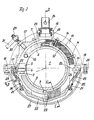
Figur 1 die Seitenansicht eines Erdungskontaktes im Schnitt gemäß der Linie D-D derFigur 2,Figur 2 die Vorderansicht des inFigur 1 dargestellten Erdungskontaktes im Schnitt, und zwar zeigt die linke Hälfte derFigur 2 einen Schnitt gemäß der Linie B-B derFigur 1 und die rechte Hälfte einen Schnitt gemäß der Linie A-A gemäßFigur 1,Figur 3 zeigt einen Schnitt gemäß der Linie C-C derFigur 2.
- 1 shows the side view of an earth contact in section along line DD of FIG. 2,
- 2 shows the front view of the grounding contact shown in FIG. 1 in section, namely the left half of FIG. 2 shows a section along line BB of FIG. 1 and the right half shows a section along line AA according to FIG. 1,
- Figure 3 shows a section along the line CC of Figure 2.
Mit 1 ist eine Radsatzwelle bezeichnet, die von zwei halbschalenförmigen Tragstücken 2 und 3 umfaßt wird. Diese Tragstücke 2 und 3 weisen im Querschnitt ein U-förmiges Profil auf, wobei die freien Schenkel 4 nach außen weisen. Mit den Tragstücken 2 und 3 sind je zwei Ansätze 5 und 6 verschweißt, die durch Schrauben 7 miteinander fest verschraubt werden, so daß die Tragstücke 2 und 3 einen einheitlichen Träger bilden und mit der Radsatzwelle 1 verklemmt sind. Auf diesen Träger 2, 3 ist ein Schleifring 7' aufgesetzt, der aus zwei miteinander über Schrauben 8 und Zentrierstifte 9 verbundenen Halbschalen besteht. Gegen Verdrehen und zur Befestigung auf dem Träger 2, 3 ist der Schleifring 7' mittels Schrauben 10 gesichert, die durch einen Schenkel des Trägers 2, hindurch in den Schleifring 7' eingedreht sind. Die äußere Mantelfläche des Schleifringes 7' ist profiliert ausgebildet und weist zwei nebeneinander umlaufende trapezförmige Nuten 11 auf. In diese Nuten 11 greifen zwei aus geeignetem Werkstück bestehende Gleitlagersegmente 12 und 13 ein, die den oberen Teil des Schleifringes 7' umfassen. Diese Gleitlagersegmente 12 und 13 sind über Schrauben 14 mit einem Gehäuse 15 verbunden, wobei letzteres, nämlich 15, einen oberen ringförmigen Aufnahmeansatz 16, eine Befestigungskonsole 17 und zwei Verbindungskragen 18 aufweist. Im Bereich der Verbindungskragen 18 sind mit dem Gehäuse 15 noch Lagerböcke 19 verbunden, die je eine gegenüber dem Gehäuse 15 isolierte Rollbandfeder 20 tragen. Mit den frei auslaufenden Enden dieser Federn 20 sind mit Durchgangsbohrungen versehene Plättchen 21 fest verbunden, die mit den Enden eines starren Bügels 22 verschraubt sind, der aus stromleitendem Material besteht. Zwischen der Innenseite dieses Bügels 22 und der unteren Hälfte des Schleifringes 7' bzw. der Nuten 11 des Schleifringes 7' liegen entsprechend profilierte Kohlebürsten 23, die aufgrund der Federkraft der Rollbandfedern 20 ständig gegen den Schleifring 7' bzw. in die Nuten 11 des Schleifringes gedrückt werden. Der über die Kohlebürsten 23 in die Radsatzwelle 1 abzuleitende Strom fließt über den in den Aufnahmeansatz 16 eingesetzten und gegenüber diesem isolierten Stecker 24, der mit einer nicht dargestellten Erdungsleitung verbunden ist, und über die mit dem Stecker 24 verlöteten Stromkabel 25 zu dem Kabelschuhen 26, die mit dem Bügel 22 fest verschraubt sind. Von dort wird der Strom über den Bügel 22, die Kohlebürsten 23, den Schleifring 7' und die Tragkörper 2, 3 in die Radsatzwelle 1 abgeleitet. Um zu verhindern, daß Bügel 22 und Kohlebürsten 23 verschmutzen oder beschädigt werden, sind sie von einer Abdeckschale 27 nach unten hin abgeschirmt, wobei die Abdeckschale 27 mit ihren Kragen 28 und den Kragen 18 des Gehäuses 15 verschraubt sind. Wie die Figur 2 zeigt, ist in die Konsole 17 eine ein Gelenk 29 tragende Stange 30 eingeschraubt. An das Gelenk 28 greift eine Momentenstange 31 an, die mit ihrem dem Gelenk 28 abgewandten Ende am nicht dargestellten Drehgestell eines Schienenfahrzeuges befestigt ist, so daß das Gehäuse 15 und somit alle mit ihm verbundenen Teile gegen Rotation gesichert sind. Auch wenn in dem dargestellten Ausführungsbeispiel der Strom ausschließlich über die Kohlebürsten 23 abgeleitet wird, so ist es durchaus im Rahmen der Erfindung möglich, die Gleitlagersegmente 12 ebenfalls als Kohlebürsten auszubilden, wobei durch entsprechende Materialauswahl der Ohmsche Widerstand bedarfsweise bestimmt werden kann. Der Stecker 24 wäre in einem solchen Fall nicht gegenüber dem Aufnahmeansatz 16 bzw. gegenüber dem Gehäuse 15 isoliert.1 with a wheel set shaft is designated, which is comprised of two half-shell-
Claims (11)
Priority Applications (1)
| Application Number | Priority Date | Filing Date | Title |
|---|---|---|---|
| AT85107720T ATE57799T1 (en) | 1984-07-19 | 1985-06-21 | EARTHING CONTACT FOR THE TRANSMISSION OF CURRENT FROM AN ELECTRICALLY OPERATED RAIL VEHICLE TO ITS WHEELSAXLE. |
Applications Claiming Priority (2)
| Application Number | Priority Date | Filing Date | Title |
|---|---|---|---|
| DE3426628A DE3426628A1 (en) | 1984-07-19 | 1984-07-19 | EARTHING CONTACT FOR TRANSMITTING THE ELECTRICITY OF AN ELECTRICALLY OPERATED RAIL VEHICLE TO ITS WHEEL SET SHAFT |
| DE3426628 | 1984-07-19 |
Publications (3)
| Publication Number | Publication Date |
|---|---|
| EP0168676A2 EP0168676A2 (en) | 1986-01-22 |
| EP0168676A3 EP0168676A3 (en) | 1987-11-04 |
| EP0168676B1 true EP0168676B1 (en) | 1990-10-24 |
Family
ID=6241052
Family Applications (1)
| Application Number | Title | Priority Date | Filing Date |
|---|---|---|---|
| EP85107720A Expired - Lifetime EP0168676B1 (en) | 1984-07-19 | 1985-06-21 | Earthing contact for the transmission of a current of an electrically supplied rail vehicle on its wheel set shaft |
Country Status (3)
| Country | Link |
|---|---|
| EP (1) | EP0168676B1 (en) |
| AT (1) | ATE57799T1 (en) |
| DE (1) | DE3426628A1 (en) |
Families Citing this family (3)
| Publication number | Priority date | Publication date | Assignee | Title |
|---|---|---|---|---|
| WO2013030615A1 (en) | 2011-08-26 | 2013-03-07 | Aktiebolaget Skf | Assembly with rotating parts with conductive fluid for earth return |
| WO2020224762A1 (en) * | 2019-05-06 | 2020-11-12 | Schunk Transit Systems Gmbh | Earthing contact and method for dissipating electric currents |
| CN112864751B (en) * | 2021-01-04 | 2022-09-16 | 中车青岛四方车辆研究所有限公司 | Rail vehicle earthing device |
Family Cites Families (8)
| Publication number | Priority date | Publication date | Assignee | Title |
|---|---|---|---|---|
| DE866525C (en) * | 1942-10-08 | 1953-02-09 | Siemens Ag | For the transmission of high currents, preferably of more than 10,000 amperes, used slip ring arrangement, especially for resistance seam welding machines |
| FR1078184A (en) * | 1952-09-24 | 1954-11-16 | Bbc Brown Boveri & Cie | Rotating head for high voltage rotary disconnectors |
| DE1183590B (en) * | 1961-07-14 | 1964-12-17 | Siemens Ag | Slip ring for electrical machines |
| DE1234775B (en) * | 1964-06-20 | 1967-02-23 | Bbc Brown Boveri & Cie | Device for power transmission from the electrical equipment to a vehicle axle of an electric traction vehicle |
| FR1547620A (en) * | 1967-10-04 | 1968-11-29 | Ferraz & Cie Lucien | Improvements in current return devices for electric rail vehicles |
| DD102647A1 (en) * | 1973-03-27 | 1973-12-20 | ||
| DD102648A1 (en) * | 1973-03-30 | 1973-12-20 | ||
| DE3150469C2 (en) * | 1981-12-19 | 1985-02-07 | Saueressig & Co, 4426 Vreden | Device for electroplating a rotary printing cylinder |
-
1984
- 1984-07-19 DE DE3426628A patent/DE3426628A1/en active Granted
-
1985
- 1985-06-21 EP EP85107720A patent/EP0168676B1/en not_active Expired - Lifetime
- 1985-06-21 AT AT85107720T patent/ATE57799T1/en not_active IP Right Cessation
Also Published As
| Publication number | Publication date |
|---|---|
| EP0168676A2 (en) | 1986-01-22 |
| ATE57799T1 (en) | 1990-11-15 |
| DE3426628A1 (en) | 1986-01-23 |
| DE3426628C2 (en) | 1988-04-28 |
| EP0168676A3 (en) | 1987-11-04 |
Similar Documents
| Publication | Publication Date | Title |
|---|---|---|
| DE3514497A1 (en) | PROTECTIVE CAP FOR CYLINDRICAL PARTS, ESPECIALLY FOR A BOLT GUIDE OF A PART COVER DISC BRAKE | |
| DE2630450C2 (en) | Rotatable pipe connection | |
| DE1953043C3 (en) | Sliding contact arrangement for power transmission between the frame and axles of electric rail vehicles | |
| CH624510A5 (en) | Electrical machine having brushes which slide on a commutator or sliprings | |
| EP0168676B1 (en) | Earthing contact for the transmission of a current of an electrically supplied rail vehicle on its wheel set shaft | |
| DE2451231B2 (en) | Line coupling for railway trains | |
| DE19654339B4 (en) | Ground contact means | |
| DE3510897C2 (en) | ||
| DE3614869C2 (en) | ||
| EP0582888A1 (en) | Earthing contact | |
| DE2607075C3 (en) | Rotatable electrical line coupling | |
| AT261362B (en) | Ring-shaped multi-work carrier | |
| DE2556336A1 (en) | MOUNTING FOOT FOR INSTALLATION DEVICES, IN PARTICULAR FOR SWITCHGEAR TERMINALS | |
| DE1091605B (en) | Exchangeable earthing contact for the axle bearings of electric rail traction vehicles | |
| DE3230453A1 (en) | Contact arrangement for electrically bridging the axle bearings of rail vehicles | |
| DE3405193C2 (en) | ||
| DE2757790C2 (en) | ||
| DE589076C (en) | Fastening device for busbars for electric railways | |
| DE1221327B (en) | Power transmission arrangement with slip rings and pantographs | |
| DE3822489C2 (en) | ||
| DE10207005A1 (en) | Arrangement for electrical rotary unions | |
| DE2232245C2 (en) | Arrangement for holding a small electrical machine | |
| DE7605177U1 (en) | Cable winding device with rotatable electrical line coupling | |
| DE1119903B (en) | Jointless pantograph | |
| DE2212951C3 (en) | Two-part device for high voltage transmission from a fixed to a rotatable machine part |
Legal Events
| Date | Code | Title | Description |
|---|---|---|---|
| PUAI | Public reference made under article 153(3) epc to a published international application that has entered the european phase |
Free format text: ORIGINAL CODE: 0009012 |
|
| 17P | Request for examination filed |
Effective date: 19850826 |
|
| AK | Designated contracting states |
Designated state(s): AT CH FR GB LI SE |
|
| PUAL | Search report despatched |
Free format text: ORIGINAL CODE: 0009013 |
|
| AK | Designated contracting states |
Kind code of ref document: A3 Designated state(s): AT CH FR GB LI SE |
|
| 17Q | First examination report despatched |
Effective date: 19891110 |
|
| GRAA | (expected) grant |
Free format text: ORIGINAL CODE: 0009210 |
|
| AK | Designated contracting states |
Kind code of ref document: B1 Designated state(s): AT CH FR GB LI SE |
|
| REF | Corresponds to: |
Ref document number: 57799 Country of ref document: AT Date of ref document: 19901115 Kind code of ref document: T |
|
| ET | Fr: translation filed | ||
| GBT | Gb: translation of ep patent filed (gb section 77(6)(a)/1977) | ||
| PLBE | No opposition filed within time limit |
Free format text: ORIGINAL CODE: 0009261 |
|
| STAA | Information on the status of an ep patent application or granted ep patent |
Free format text: STATUS: NO OPPOSITION FILED WITHIN TIME LIMIT |
|
| 26N | No opposition filed | ||
| PGFP | Annual fee paid to national office [announced via postgrant information from national office to epo] |
Ref country code: SE Payment date: 19930415 Year of fee payment: 9 |
|
| PGFP | Annual fee paid to national office [announced via postgrant information from national office to epo] |
Ref country code: GB Payment date: 19930618 Year of fee payment: 9 |
|
| PGFP | Annual fee paid to national office [announced via postgrant information from national office to epo] |
Ref country code: AT Payment date: 19930625 Year of fee payment: 9 |
|
| PGFP | Annual fee paid to national office [announced via postgrant information from national office to epo] |
Ref country code: FR Payment date: 19940615 Year of fee payment: 10 |
|
| PG25 | Lapsed in a contracting state [announced via postgrant information from national office to epo] |
Ref country code: GB Effective date: 19940621 Ref country code: AT Effective date: 19940621 |
|
| PG25 | Lapsed in a contracting state [announced via postgrant information from national office to epo] |
Ref country code: SE Effective date: 19940622 |
|
| PGFP | Annual fee paid to national office [announced via postgrant information from national office to epo] |
Ref country code: CH Payment date: 19940830 Year of fee payment: 10 |
|
| EUG | Se: european patent has lapsed |
Ref document number: 85107720.6 Effective date: 19950110 |
|
| GBPC | Gb: european patent ceased through non-payment of renewal fee |
Effective date: 19940621 |
|
| EUG | Se: european patent has lapsed |
Ref document number: 85107720.6 |
|
| PG25 | Lapsed in a contracting state [announced via postgrant information from national office to epo] |
Ref country code: LI Effective date: 19950630 Ref country code: CH Effective date: 19950630 |
|
| PG25 | Lapsed in a contracting state [announced via postgrant information from national office to epo] |
Ref country code: FR Effective date: 19960229 |
|
| REG | Reference to a national code |
Ref country code: CH Ref legal event code: PL |
|
| REG | Reference to a national code |
Ref country code: FR Ref legal event code: ST |