EP0168657B1 - Method and equipment for rapid, automatic chemical-clinical analysis - Google Patents
Method and equipment for rapid, automatic chemical-clinical analysis Download PDFInfo
- Publication number
- EP0168657B1 EP0168657B1 EP85107526A EP85107526A EP0168657B1 EP 0168657 B1 EP0168657 B1 EP 0168657B1 EP 85107526 A EP85107526 A EP 85107526A EP 85107526 A EP85107526 A EP 85107526A EP 0168657 B1 EP0168657 B1 EP 0168657B1
- Authority
- EP
- European Patent Office
- Prior art keywords
- receptacles
- detecting device
- row
- samples
- field
- Prior art date
- Legal status (The legal status is an assumption and is not a legal conclusion. Google has not performed a legal analysis and makes no representation as to the accuracy of the status listed.)
- Expired
Links
Images


Classifications
-
- G—PHYSICS
- G01—MEASURING; TESTING
- G01N—INVESTIGATING OR ANALYSING MATERIALS BY DETERMINING THEIR CHEMICAL OR PHYSICAL PROPERTIES
- G01N21/00—Investigating or analysing materials by the use of optical means, i.e. using sub-millimetre waves, infrared, visible or ultraviolet light
- G01N21/17—Systems in which incident light is modified in accordance with the properties of the material investigated
- G01N21/25—Colour; Spectral properties, i.e. comparison of effect of material on the light at two or more different wavelengths or wavelength bands
- G01N21/251—Colorimeters; Construction thereof
- G01N21/253—Colorimeters; Construction thereof for batch operation, i.e. multisample apparatus
-
- G—PHYSICS
- G01—MEASURING; TESTING
- G01N—INVESTIGATING OR ANALYSING MATERIALS BY DETERMINING THEIR CHEMICAL OR PHYSICAL PROPERTIES
- G01N35/00—Automatic analysis not limited to methods or materials provided for in any single one of groups G01N1/00 - G01N33/00; Handling materials therefor
- G01N35/02—Automatic analysis not limited to methods or materials provided for in any single one of groups G01N1/00 - G01N33/00; Handling materials therefor using a plurality of sample containers moved by a conveyor system past one or more treatment or analysis stations
- G01N35/026—Automatic analysis not limited to methods or materials provided for in any single one of groups G01N1/00 - G01N33/00; Handling materials therefor using a plurality of sample containers moved by a conveyor system past one or more treatment or analysis stations having blocks or racks of reaction cells or cuvettes
-
- B—PERFORMING OPERATIONS; TRANSPORTING
- B01—PHYSICAL OR CHEMICAL PROCESSES OR APPARATUS IN GENERAL
- B01J—CHEMICAL OR PHYSICAL PROCESSES, e.g. CATALYSIS OR COLLOID CHEMISTRY; THEIR RELEVANT APPARATUS
- B01J2219/00—Chemical, physical or physico-chemical processes in general; Their relevant apparatus
- B01J2219/00274—Sequential or parallel reactions; Apparatus and devices for combinatorial chemistry or for making arrays; Chemical library technology
- B01J2219/00277—Apparatus
- B01J2219/00457—Dispensing or evacuation of the solid phase support
- B01J2219/00459—Beads
- B01J2219/00468—Beads by manipulation of individual beads
-
- G—PHYSICS
- G01—MEASURING; TESTING
- G01N—INVESTIGATING OR ANALYSING MATERIALS BY DETERMINING THEIR CHEMICAL OR PHYSICAL PROPERTIES
- G01N2201/00—Features of devices classified in G01N21/00
- G01N2201/12—Circuits of general importance; Signal processing
- G01N2201/122—Kinetic analysis; determining reaction rate
-
- Y—GENERAL TAGGING OF NEW TECHNOLOGICAL DEVELOPMENTS; GENERAL TAGGING OF CROSS-SECTIONAL TECHNOLOGIES SPANNING OVER SEVERAL SECTIONS OF THE IPC; TECHNICAL SUBJECTS COVERED BY FORMER USPC CROSS-REFERENCE ART COLLECTIONS [XRACs] AND DIGESTS
- Y10—TECHNICAL SUBJECTS COVERED BY FORMER USPC
- Y10S—TECHNICAL SUBJECTS COVERED BY FORMER USPC CROSS-REFERENCE ART COLLECTIONS [XRACs] AND DIGESTS
- Y10S435/00—Chemistry: molecular biology and microbiology
- Y10S435/807—Gas detection apparatus
-
- Y—GENERAL TAGGING OF NEW TECHNOLOGICAL DEVELOPMENTS; GENERAL TAGGING OF CROSS-SECTIONAL TECHNOLOGIES SPANNING OVER SEVERAL SECTIONS OF THE IPC; TECHNICAL SUBJECTS COVERED BY FORMER USPC CROSS-REFERENCE ART COLLECTIONS [XRACs] AND DIGESTS
- Y10—TECHNICAL SUBJECTS COVERED BY FORMER USPC
- Y10S—TECHNICAL SUBJECTS COVERED BY FORMER USPC CROSS-REFERENCE ART COLLECTIONS [XRACs] AND DIGESTS
- Y10S435/00—Chemistry: molecular biology and microbiology
- Y10S435/809—Incubators or racks or holders for culture plates or containers
Definitions
- the present invention concerns the method and apparatus for automating clinical analysis, especially in cases where a series of consecutive values must be obtained. All methods tried so far have revealed defects limits, inconveniences, been too slow and required manual intervention. As a result, many methods already discovered have been inevitably shelved and the search for new ones stimulated. In particular, the following have been used:
- US-A-3,344,702 is also known. This patent shows a set of adjoining receptacles which are not dealt with as a unit and which are moved discontinuously. No provision is foreseen for automatically handling the receptacles. They must be moved by hand one at a time.
- US-A-3,847,486 discloses an apparatus according to the preamble of Claim 2, using, however, a cuvette wheel quasi-continuously rotating in one direction.
- the aim of the invention in question is to eliminate all these defects and provide a very versatile and quick-operating piece of equipment. In fact, it is also to:
- the apparatus in question ( Figure 1 and Figure 2) includes a support frame 6, inside of which are housed rows of adjoining receptacles 12 forming a set 5 of receptacles.
- the invention in question has a device which gives a reciprocating motion to a set 5 of receptacles 12 (Figure 2), made up of a row of adjoining receptacles 12.
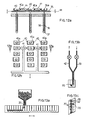
- Figures 3a and 3b a conveyor belt 20 is fitted with a coupling device 21, moved by cams 22a, b, c and d which move the coupling device to and from the set 5 of receptacles.
- Figure 4 there is a rotating disk 23 with a rod 24 pivoted on its edge. The other end of the rod is pivoted on the set 5 of receptacles.
- Figure 5 shows actuating device which uses a conveyor belt on which the set 5 of receptacles is fitted. The conveyor belt 25 is moved in both directions by a stepping motor, which is not depicted.
- Figure 6 shows another actuating device which uses a pinion 26 and rack 27, on which the set 5 of receptacles is fitted.
- the pinion is moved in both directions.
- All of these devices are able to move the set 5 of receptacles in a cycle from right to left and vice-versa.
- the actuating device giving a back-and- forth motion allows each receptacle forming the set to pass at each cycle in front of one or more detecting devices 18 (for example, the optical-photoelectric type) and undergoes photometric analysis at a high repetition rate.
- a set is moved by a handling device.
- This set has many sections forming the receptacles 12 and four coupling devices 11 (for example, magnets), fitted at the top of each corner. These are for moving the set of receptacles by means of the bridge crane 13 depicted in Figure 9.
- Each receptacle has two transparent sides 10 ( Figure 8) which allow reading by the detecting device 18.
- Magnetic microbars 19 ( Figure 7) can be fitted to the set of receptacles. They are moved by a motor equipped with a magnetic device in order to give a shaking action.
- Solid carriers 20, for example globular immunoenzymes (Figure 13a) can be used with this set.
- each receptacle 12 has an 8-shaped section (seen in Figure 13c), in which a narrowing prevents contact between the solid carrier 20 and the tubes 29 and 42 for introducing and withdrawing the reagents or solutions.
- the set of receptacles seen in Figure 2 can be used for fluorimetric analysis.
- a beam of light from a lamp 34 passes.
- Chemical-clinical analyses in which the optical density is measured are carried out using set of receptacles like 56 ( Figure 11b), whose single receptacles 12b are cylindrical.
- Figure 11c the set 5c of receptacles used for analyses in which the state of aggregation of blood groups is read.
- a bridge crane 13 ( Figure 9) which which can be moved in the three directions 14, 15 and 16 respectively may also be included in the equipment in question. It is fitted with four holding devices, for example automatic, magnetic grippers 17, for moving the set 5 of receptacles. These holding devices are positioned in line with the coupling devices on the set 5 of receptacles.
- the detecting device 18 for example, the optical-photoelectric type is suitable for detecting the values from the set of receptacles at high speed and repeating the detecting at each cycle. It sends all the data collected to an A/D converter 39, an interface 30 and a CPU and printer 31, and then onto a floppy disk 32. In this way a printed readout 33 is provided for each sample analysed.
- a multiple system of automatically selected microsyringes may also be included. It serves to introduce reagents or solutions at consecutive moments. It is fitted with a plate 35 which moves vertically (arrow 44) and is connected to a number of pistons 36 with plungers 37 made of a material suitable for use in a glass (or other material), capillary sleeve 38. The result is a multiple, capillary microsyringe.
- An electromagnetic device activates or deactivates a series of keys 40 with slits 40a which engage or disengage the head 36a of each piston 36. The keys are moved by pushing devices 41.
- Figure 12 shows only one microsyringe being operated by the plate's 35 vertical movement.
- the equipment can be fitted with a filtering device for separating and retrieving the filtrates from the top part of the solution, as well as a device for separating, retrieving and treating two or more products.
Description
- The present invention concerns the method and apparatus for automating clinical analysis, especially in cases where a series of consecutive values must be obtained. All methods tried so far have revealed defects limits, inconveniences, been too slow and required manual intervention. As a result, many methods already discovered have been inevitably shelved and the search for new ones stimulated. In particular, the following have been used:
- 1) Discrete, large-volume systems with forward motion on a twelve-position (analyses) conveyor belt. These systems have been shelved due to the high consumption of reagents and their limited flexibility (only 12 analyses).
- 2) The system with one main conveyor belt (for the samples) and any desired number of secondary belts (for the reactions) with end readers for values and EDP coordination. This system is slow, bulky and very expensive.
- 3) The multichannel, continual-flow system. This causes big problems of subsquent samples being contaminated in the reaction tubes, leading to very imprecise results. Moreover, it is unable to select only the required reactiqns and is slow and very inflexible. To change one analysis program for another is a very complex operation.
- 4) The centrifugal system. It is very fast but needs a lot of manual intervention to change plates for each analysis. Furthermore, considerable manual intervention is also required, with the possibility of error, for matching the separator positions with the samples arranged on the series of plates.
- 5) Multiple systems using optical fibers. A simultaneous, static reading occurs with the number of photodetectors corresponding to the number of channels used. An identical readout is not achieved, because of the photodetectors being different. The stage for preparing the reagents has not been automated. Computer elaboration is good but a lot of manual intervention is required in the intermediary stages. It cannot be considered an automatic, but rather a semiautomatic system.
- 6) Sequential systems with reading of samples on a conveyor belt, but with random arrangement of both samples and reactions. This type of system is slow. The samples are read one by one and for the kinetic reactions it is necessary to wait for the reaction to develop or to reduce the reading time, resulting in a decrease in accuracy.
- US-A-3,344,702 is also known. This patent shows a set of adjoining receptacles which are not dealt with as a unit and which are moved discontinuously. No provision is foreseen for automatically handling the receptacles. They must be moved by hand one at a time. US-A-3,847,486 discloses an apparatus according to the preamble of Claim 2, using, however, a cuvette wheel quasi-continuously rotating in one direction.
- The aim of the invention in question is to eliminate all these defects and provide a very versatile and quick-operating piece of equipment. In fact, it is also to:
- 1) accept all samples in a random order and analyse them in batches of 20, 50 or 100 at a time (or more);
- 2) accept just one sample for urgent cases;
- 3) simultaneously produce all the reactions required for each sample, likewise in batches of 20, 50, 100 or more at a time;
- 4) add reagents only for the reactions required and not for all reactions (selective);
- 5) simultaneously agitate and thermostat all samples, allowing them to be incubated for as long as required;
- 6) simultaneously read very rapidly the end point reactions with final, stable colouring of batches of 20, 50, 100 samples and repeatedly at very close intervals the kinetic reactions. In practice, the time needed is reduced in proportion to the number of sections used (20, 50, 100 or more). The same method of fluorescent and nephelometric reading is used;
- 7) elaborate without manual intervention all the EDP data, store and coordinate the analytical reports by sample and analysis and supply all the statistical data required; day, month, year frequency; progressive figures; statistics for each type of analysis; pathological percentages and calculation of standard error;
- 8) allow automatic check of errors (deviation) by the use of standard deviations intercalated with the samples, the readings being automatically corrected by shifting the zero line and the optimal reading values, etc.;
- 9) allow multiple applications with different types of reaction such as, study of coagulation, reading of blood groups, yes or no type reactors, immunoturbidimetric reactions, immunoenzymatic reactions, etc;
- 10) carry out any chemical process, even the most complex and arduous, add an unlimited number of reagents, add solid reagents or solid carriers, for example, globular types composed of reagents or enzymes or immunoenzymatic material; and then to remove the reagents after the reaction, wash the solid carriers, incubate the samples or reactions in course, thermostat, etc.
- The main aim has been achieved as specified in Claims 1 and 2. Other advantageous embodiments are described in Claims 3-7.
- This invention will now be explained in greater detail with the aid of the actual examples depicted in the enclosed drawings, in which:
- Figure 1 is a top view of the apparatus in question with two rows of receptacles side by side, ready to be moved towards the detecting device in a reciprocating motion;
- Figure 2 is a perspective view of a row of receptacles;
- Figures 3a and 3b are a side view and a top view respectively of a first device for giving the reciprocating motion;
- Figure 4 is a side view of a second device as an alternative to the one shown in Figures 3a and 3b;
- Figure 5 is a schematic view of a third device as an alternative to the one shown in Figures 3a and 3b;
- Figure 6 is a schematic view of a fourth device as an alternative to the one shown in Figures 3a and 3b;
- Figure 7 is a side view of a receptacle and an agitator;
- Figure 8 is a view of an optical-type detecting device;
- Figure 9 is a view of the bridge crane;
- Figure 10 shows the flow chart for the detecting device;
- Figures 11a to 11d are perspective views of different kinds of receptacles;
- Figures 12 and 12b are views of a vertical section along the line 11-11 of Figure 11 b and a plan of a system of microsyringes respectively;
- Figures 13a, 13b and 13c are views which show a row of special receptacles into which reactive globules can be introduced.
- The apparatus in question (Figure 1 and Figure 2) includes a
support frame 6, inside of which are housed rows of adjoiningreceptacles 12 forming aset 5 of receptacles. - The invention in question has a device which gives a reciprocating motion to a
set 5 of receptacles 12 (Figure 2), made up of a row ofadjoining receptacles 12. There are different versions of the actuating device. In Figures 3a and 3b aconveyor belt 20 is fitted with acoupling device 21, moved bycams 22a, b, c and d which move the coupling device to and from theset 5 of receptacles. - In another version (Figure 4) there is a rotating
disk 23 with arod 24 pivoted on its edge. The other end of the rod is pivoted on theset 5 of receptacles. Figure 5, on the other hand, shows actuating device which uses a conveyor belt on which theset 5 of receptacles is fitted. Theconveyor belt 25 is moved in both directions by a stepping motor, which is not depicted. - Figure 6 shows another actuating device which uses a
pinion 26 andrack 27, on which theset 5 of receptacles is fitted. The pinion is moved in both directions. - All of these devices are able to move the
set 5 of receptacles in a cycle from right to left and vice-versa. The actuating device giving a back-and- forth motion allows each receptacle forming the set to pass at each cycle in front of one or more detecting devices 18 (for example, the optical-photoelectric type) and undergoes photometric analysis at a high repetition rate. - This ensures the possibility of carrying out many series of readings of slow reaction analysis (kinetic reactions), whose incremental values stabilize through time. It also ensures that with the use of suitable detecting devices the following can be read: all end point, fluorimetric, immunoturbidimetric, coagulation and blood group reactions.
- A set is moved by a handling device. This set has many sections forming the
receptacles 12 and four coupling devices 11 (for example, magnets), fitted at the top of each corner. These are for moving the set of receptacles by means of thebridge crane 13 depicted in Figure 9. Each receptacle has two transparent sides 10 (Figure 8) which allow reading by the detectingdevice 18. Magnetic microbars 19 (Figure 7) can be fitted to the set of receptacles. They are moved by a motor equipped with a magnetic device in order to give a shaking action.Solid carriers 20, for example globular immunoenzymes (Figure 13a), can be used with this set. The special version can be washed continuously with suitable reactive solutions (Figures 13b and 13c), even when containing the above-saidsolid carriers 20. In this case, eachreceptacle 12 has an 8-shaped section (seen in Figure 13c), in which a narrowing prevents contact between thesolid carrier 20 and thetubes - The set of receptacles seen in Figure 2 can be used for fluorimetric analysis. For nephelometric analyses it is better to use the
set 5a of receptacles depicted in Figure 11a. Through eachreceptacle 12a a beam of light from alamp 34 passes. Chemical-clinical analyses in which the optical density is measured are carried out using set of receptacles like 56 (Figure 11b), whose single receptacles 12b are cylindrical. Finally, there are the set 5c of receptacles (Figure 11c) used for analyses in which the state of aggregation of blood groups is read. - A bridge crane 13 (Figure 9) which which can be moved in the three
directions magnetic grippers 17, for moving theset 5 of receptacles. These holding devices are positioned in line with the coupling devices on theset 5 of receptacles. - The detecting device 18 (Figure 10), for example, the optical-photoelectric type is suitable for detecting the values from the set of receptacles at high speed and repeating the detecting at each cycle. It sends all the data collected to an A/
D converter 39, aninterface 30 and a CPU andprinter 31, and then onto afloppy disk 32. In this way a printedreadout 33 is provided for each sample analysed. - A multiple system of automatically selected microsyringes (Figure 12a) may also be included. It serves to introduce reagents or solutions at consecutive moments. It is fitted with a
plate 35 which moves vertically (arrow 44) and is connected to a number of pistons 36 withplungers 37 made of a material suitable for use in a glass (or other material),capillary sleeve 38. The result is a multiple, capillary microsyringe. An electromagnetic device activates or deactivates a series ofkeys 40 withslits 40a which engage or disengage thehead 36a of each piston 36. The keys are moved by pushingdevices 41. Figure 12 shows only one microsyringe being operated by the plate's 35 vertical movement. - Furthermore, the equipment can be fitted with a filtering device for separating and retrieving the filtrates from the top part of the solution, as well as a device for separating, retrieving and treating two or more products.
Claims (7)
Applications Claiming Priority (2)
| Application Number | Priority Date | Filing Date | Title |
|---|---|---|---|
| IT21496/84A IT1174039B (en) | 1984-06-19 | 1984-06-19 | METHOD AND EQUIPMENT FOR HIGH SPEED AUTOMATIC CHEMICAL-CLINICAL ANALYSIS |
| IT2149684 | 1984-06-19 |
Publications (2)
| Publication Number | Publication Date |
|---|---|
| EP0168657A1 EP0168657A1 (en) | 1986-01-22 |
| EP0168657B1 true EP0168657B1 (en) | 1989-03-29 |
Family
ID=11182680
Family Applications (1)
| Application Number | Title | Priority Date | Filing Date |
|---|---|---|---|
| EP85107526A Expired EP0168657B1 (en) | 1984-06-19 | 1985-06-18 | Method and equipment for rapid, automatic chemical-clinical analysis |
Country Status (5)
| Country | Link |
|---|---|
| US (1) | US4767600A (en) |
| EP (1) | EP0168657B1 (en) |
| JP (1) | JPS6144358A (en) |
| DE (1) | DE3569157D1 (en) |
| IT (1) | IT1174039B (en) |
Families Citing this family (19)
| Publication number | Priority date | Publication date | Assignee | Title |
|---|---|---|---|---|
| US4857454A (en) * | 1987-04-09 | 1989-08-15 | a Division of Yeshiva University Albert Einstein College of Medicine of Yeshiva University | Spectrophotometric method for kinetic absorbance measurements in two-phase enzyme immunoassay and apparatus therefor |
| US5094818A (en) * | 1989-05-04 | 1992-03-10 | Exact Science, Inc. | Self-filling anti-siphon flow system for particle analysis |
| US5271899A (en) * | 1992-07-17 | 1993-12-21 | Bio-Chem Laboratory Systems, Inc. | Chemistry analyzer |
| US5681530A (en) * | 1993-06-11 | 1997-10-28 | Ortho Diagnostic Systems Inc. | Transport system for fluid analysis instrument |
| US5594808A (en) * | 1993-06-11 | 1997-01-14 | Ortho Diagnostic Systems Inc. | Method and system for classifying agglutination reactions |
| US6800452B1 (en) | 1994-08-08 | 2004-10-05 | Science Applications International Corporation | Automated methods for simultaneously performing a plurality of signal-based assays |
| US5885529A (en) * | 1996-06-28 | 1999-03-23 | Dpc Cirrus, Inc. | Automated immunoassay analyzer |
| JP2001527642A (en) * | 1997-01-17 | 2001-12-25 | スミスクライン・ビーチャム・コーポレイション | Apparatus and method for arranging beads |
| US8448499B2 (en) * | 2008-12-23 | 2013-05-28 | C A Casyso Ag | Cartridge device for a measuring system for measuring viscoelastic characteristics of a sample liquid, a corresponding measuring system, and a corresponding method |
| EP2371284A1 (en) | 2010-03-24 | 2011-10-05 | C A Casyso AG | Method and apparatus for determining at least one evaluation parameter of a blood sample |
| US10288630B2 (en) | 2014-09-29 | 2019-05-14 | C A Casyso Gmbh | Blood testing system and method |
| US10816559B2 (en) | 2014-09-29 | 2020-10-27 | Ca Casyso Ag | Blood testing system and method |
| US9897618B2 (en) | 2014-09-29 | 2018-02-20 | C A Casyso Gmbh | Blood testing system |
| US10175225B2 (en) | 2014-09-29 | 2019-01-08 | C A Casyso Ag | Blood testing system and method |
| US10539579B2 (en) | 2014-09-29 | 2020-01-21 | C A Casyso Gmbh | Blood testing system and method |
| USD777343S1 (en) | 2015-05-28 | 2017-01-24 | C A Casyso Ag | Body fluid cartridge device |
| US10295554B2 (en) | 2015-06-29 | 2019-05-21 | C A Casyso Gmbh | Blood testing system and method |
| US10473674B2 (en) | 2016-08-31 | 2019-11-12 | C A Casyso Gmbh | Controlled blood delivery to mixing chamber of a blood testing cartridge |
| US10843185B2 (en) | 2017-07-12 | 2020-11-24 | Ca Casyso Gmbh | Autoplatelet cartridge device |
Family Cites Families (32)
| Publication number | Priority date | Publication date | Assignee | Title |
|---|---|---|---|---|
| GB977829A (en) * | 1960-09-07 | 1964-12-16 | Gilford Instr Labor Inc | Improvements in or relating to optical density analytical apparatus |
| US3504259A (en) * | 1966-04-11 | 1970-03-31 | Thomas Co Arthur H | Automatic positioner for testing samples |
| US3578412A (en) * | 1968-01-22 | 1971-05-11 | Beckman Instruments Inc | Automated transport system |
| US3731820A (en) * | 1969-07-08 | 1973-05-08 | Nagoya Kiko Co Ltd | Rectilinear motion device for a mechanical handling machine |
| US3897216A (en) * | 1971-11-03 | 1975-07-29 | Coulter Chemistry Inc | Sample cup holder |
| US3847486A (en) * | 1972-06-07 | 1974-11-12 | W Mccabe | Automated spectrophotometer apparatus and computer system for simulataneous measurement of a plurality of kinetic reactions |
| DE2350296A1 (en) * | 1972-10-18 | 1974-05-02 | Electrolux Ab | FASTENER ON A ROBOT |
| FR2258625A1 (en) * | 1974-01-23 | 1975-08-18 | Fontenille Michel | Automatic sequential chemical analyser - uses programmed sequence of preparation, processing and sharing for analysis |
| DE2405810B2 (en) * | 1974-02-07 | 1977-07-07 | Fa. Carl Zeiss, 7920 Heidenheim | DIGITAL PHOTOMETER FOR THE INDEPENDENT MEASUREMENT OF THE ENZYMACTIVITY OF SEVERAL SAMPLES |
| US3985507A (en) * | 1975-09-05 | 1976-10-12 | International Business Machines Corporation | Automatic test sample handling system |
| US4053284A (en) * | 1976-03-10 | 1977-10-11 | Akzona Incorporated | Continuous flow apparatus for biological testing |
| US4011048A (en) * | 1976-06-17 | 1977-03-08 | Micromedic Systems, Inc. | Incubation apparatus |
| JPS5756209Y2 (en) * | 1976-11-02 | 1982-12-03 | ||
| FR2396969A1 (en) * | 1977-07-06 | 1979-02-02 | Pasteur Institut | DEVICE AND METHOD FOR MULTIPLE ANALYZES |
| FI59934C (en) * | 1978-07-05 | 1981-11-10 | Suovaniemi Finnpipette | FOERFLYTTNINGSANORDNING FOER ANALYSANLAEGGNINGAR |
| US4387991A (en) * | 1978-08-01 | 1983-06-14 | Gilford Instrument Laboratories, Inc. | Automatic monochromatic light absorbance measurement analyzer |
| JPS5571951A (en) * | 1978-11-24 | 1980-05-30 | Toshiba Corp | Automatic chemical analyzer |
| US4330627A (en) * | 1979-02-09 | 1982-05-18 | Ryder International Corporation | Testing tray |
| JPS562561A (en) * | 1979-06-21 | 1981-01-12 | Olympus Optical Co Ltd | Deciding method for particle coagulation pattern |
| JPS6145479Y2 (en) * | 1979-09-10 | 1986-12-20 | ||
| FR2507325A1 (en) * | 1981-06-05 | 1982-12-10 | Guigan Jean | METHOD AND DEVICE FOR THE SUCCESSIVE CONTACT OF A LIQUID SAMPLE WITH MULTIPLE REAGENTS |
| US4351799A (en) * | 1981-07-15 | 1982-09-28 | Gross Valery N | Micrometering liquid sample dispenser |
| FR2511153B1 (en) * | 1981-08-05 | 1986-01-10 | Materiel Biomedical | MULTIPLE CONTAINER REACTION HOLDER FOR TESTING LIQUID DOSES |
| JPS5832144A (en) * | 1981-08-19 | 1983-02-25 | Olympus Optical Co Ltd | Decision apparatus of particle agglutination |
| JPS5848858A (en) * | 1981-09-17 | 1983-03-22 | Horiba Ltd | Automatic metal analyzing device |
| JPS5848836A (en) * | 1981-09-18 | 1983-03-22 | Toa Medical Electronics Co Ltd | Optical type automatic analyzing and measuring device |
| JPH0230470B2 (en) * | 1981-10-09 | 1990-07-06 | Olympus Optical Co | RYUSHIGYOSHUPATAANKENSAHOHOOYOBISOCHI |
| JPS5882164A (en) * | 1981-11-12 | 1983-05-17 | Toshiba Corp | Sample information recognition mechanism for automatic chemical analyzer |
| JPS58105065A (en) * | 1981-12-17 | 1983-06-22 | Olympus Optical Co Ltd | Analyzer based on emmunological agglutination |
| US4457896A (en) * | 1982-08-02 | 1984-07-03 | Institute Of Gas Technology | Apparatus and process for fluidized solids systems |
| US4478094A (en) * | 1983-01-21 | 1984-10-23 | Cetus Corporation | Liquid sample handling system |
| US4681742A (en) * | 1984-10-01 | 1987-07-21 | Cetus Corporation | Assay tray |
-
1984
- 1984-06-19 IT IT21496/84A patent/IT1174039B/en active
-
1985
- 1985-06-18 DE DE8585107526T patent/DE3569157D1/en not_active Expired
- 1985-06-18 EP EP85107526A patent/EP0168657B1/en not_active Expired
- 1985-06-19 JP JP60133890A patent/JPS6144358A/en active Pending
- 1985-06-19 US US07/746,583 patent/US4767600A/en not_active Expired - Fee Related
Also Published As
| Publication number | Publication date |
|---|---|
| IT8421496A1 (en) | 1985-12-19 |
| DE3569157D1 (en) | 1989-05-03 |
| EP0168657A1 (en) | 1986-01-22 |
| US4767600A (en) | 1988-08-30 |
| IT1174039B (en) | 1987-06-24 |
| IT8421496A0 (en) | 1984-06-19 |
| JPS6144358A (en) | 1986-03-04 |
Similar Documents
| Publication | Publication Date | Title |
|---|---|---|
| EP0168657B1 (en) | Method and equipment for rapid, automatic chemical-clinical analysis | |
| US4681742A (en) | Assay tray | |
| EP0657031B1 (en) | Automated chemical analyzer with apparatus and method for conveying and temporary storage of sample tubes | |
| US5681530A (en) | Transport system for fluid analysis instrument | |
| EP1465728B1 (en) | Stackable aliquot vessel array | |
| EP0825445B1 (en) | Automatic biochemical analyzer | |
| EP0351988B1 (en) | Bio-fluid assay apparatus | |
| AU665853B2 (en) | Sample tube carrier | |
| US7943100B2 (en) | Cuvette for in vitro diagnosis | |
| AU738336B2 (en) | Control method and apparatus for controlling magnetic particles by a sample distributor | |
| AU2022256123A1 (en) | Automated diagnostic analyzer and method for its operation | |
| KR20220018612A (en) | High throughput system for performing assays using electrochemiluminescence including a consumable shaking apparatus | |
| US6808304B2 (en) | Method for mixing liquid samples using a linear oscillation stroke | |
| CA2650258A1 (en) | Automated continuous and random access analytical system | |
| AU643732B2 (en) | Apparatus for automatically carrying out a multi-stage immunoassay of at least one biological substance in a plurality of biological samples; method and reagent using said apparatus | |
| EP0889328A1 (en) | Automatic immunological analyzer | |
| DE10011547T1 (en) | System and method for incubating the contents of a reaction vessel | |
| AU645984B2 (en) | Automated laboratory apparatus | |
| WO1987006716A1 (en) | Liquid light tube end cap assembly | |
| US5474742A (en) | Apparatus for removing solid bodies from an array of reaction vessels | |
| CA2096198A1 (en) | Automated clinical analyzer with temperature control | |
| US5324479A (en) | Analyzer for the determination of the phenotype and the ABO blood group |
Legal Events
| Date | Code | Title | Description |
|---|---|---|---|
| PUAI | Public reference made under article 153(3) epc to a published international application that has entered the european phase |
Free format text: ORIGINAL CODE: 0009012 |
|
| AK | Designated contracting states |
Designated state(s): DE FR GB NL SE |
|
| 17P | Request for examination filed |
Effective date: 19860619 |
|
| 17Q | First examination report despatched |
Effective date: 19871023 |
|
| GRAA | (expected) grant |
Free format text: ORIGINAL CODE: 0009210 |
|
| AK | Designated contracting states |
Kind code of ref document: B1 Designated state(s): DE FR GB NL SE |
|
| PG25 | Lapsed in a contracting state [announced via postgrant information from national office to epo] |
Ref country code: SE Effective date: 19890329 Ref country code: NL Effective date: 19890329 Ref country code: FR Free format text: THE PATENT HAS BEEN ANNULLED BY A DECISION OF A NATIONAL AUTHORITY Effective date: 19890329 |
|
| REF | Corresponds to: |
Ref document number: 3569157 Country of ref document: DE Date of ref document: 19890503 |
|
| PG25 | Lapsed in a contracting state [announced via postgrant information from national office to epo] |
Ref country code: GB Effective date: 19890618 |
|
| EN | Fr: translation not filed | ||
| NLV1 | Nl: lapsed or annulled due to failure to fulfill the requirements of art. 29p and 29m of the patents act | ||
| PLBE | No opposition filed within time limit |
Free format text: ORIGINAL CODE: 0009261 |
|
| STAA | Information on the status of an ep patent application or granted ep patent |
Free format text: STATUS: NO OPPOSITION FILED WITHIN TIME LIMIT |
|
| GBPC | Gb: european patent ceased through non-payment of renewal fee | ||
| PG25 | Lapsed in a contracting state [announced via postgrant information from national office to epo] |
Ref country code: DE Effective date: 19900301 |
|
| 26N | No opposition filed |