EP0168361A2 - Wasservorratsbehälter - Google Patents
Wasservorratsbehälter Download PDFInfo
- Publication number
- EP0168361A2 EP0168361A2 EP85830175A EP85830175A EP0168361A2 EP 0168361 A2 EP0168361 A2 EP 0168361A2 EP 85830175 A EP85830175 A EP 85830175A EP 85830175 A EP85830175 A EP 85830175A EP 0168361 A2 EP0168361 A2 EP 0168361A2
- Authority
- EP
- European Patent Office
- Prior art keywords
- reservoir
- water
- tank
- pipe
- feeding
- Prior art date
- Legal status (The legal status is an assumption and is not a legal conclusion. Google has not performed a legal analysis and makes no representation as to the accuracy of the status listed.)
- Withdrawn
Links
Images
Classifications
-
- E—FIXED CONSTRUCTIONS
- E03—WATER SUPPLY; SEWERAGE
- E03B—INSTALLATIONS OR METHODS FOR OBTAINING, COLLECTING, OR DISTRIBUTING WATER
- E03B11/00—Arrangements or adaptations of tanks for water supply
-
- Y—GENERAL TAGGING OF NEW TECHNOLOGICAL DEVELOPMENTS; GENERAL TAGGING OF CROSS-SECTIONAL TECHNOLOGIES SPANNING OVER SEVERAL SECTIONS OF THE IPC; TECHNICAL SUBJECTS COVERED BY FORMER USPC CROSS-REFERENCE ART COLLECTIONS [XRACs] AND DIGESTS
- Y02—TECHNOLOGIES OR APPLICATIONS FOR MITIGATION OR ADAPTATION AGAINST CLIMATE CHANGE
- Y02A—TECHNOLOGIES FOR ADAPTATION TO CLIMATE CHANGE
- Y02A20/00—Water conservation; Efficient water supply; Efficient water use
-
- Y—GENERAL TAGGING OF NEW TECHNOLOGICAL DEVELOPMENTS; GENERAL TAGGING OF CROSS-SECTIONAL TECHNOLOGIES SPANNING OVER SEVERAL SECTIONS OF THE IPC; TECHNICAL SUBJECTS COVERED BY FORMER USPC CROSS-REFERENCE ART COLLECTIONS [XRACs] AND DIGESTS
- Y10—TECHNICAL SUBJECTS COVERED BY FORMER USPC
- Y10T—TECHNICAL SUBJECTS COVERED BY FORMER US CLASSIFICATION
- Y10T137/00—Fluid handling
- Y10T137/2931—Diverse fluid containing pressure systems
- Y10T137/3115—Gas pressure storage over or displacement of liquid
- Y10T137/3127—With gas maintenance or application
-
- Y—GENERAL TAGGING OF NEW TECHNOLOGICAL DEVELOPMENTS; GENERAL TAGGING OF CROSS-SECTIONAL TECHNOLOGIES SPANNING OVER SEVERAL SECTIONS OF THE IPC; TECHNICAL SUBJECTS COVERED BY FORMER USPC CROSS-REFERENCE ART COLLECTIONS [XRACs] AND DIGESTS
- Y10—TECHNICAL SUBJECTS COVERED BY FORMER USPC
- Y10T—TECHNICAL SUBJECTS COVERED BY FORMER US CLASSIFICATION
- Y10T137/00—Fluid handling
- Y10T137/8593—Systems
- Y10T137/86187—Plural tanks or compartments connected for serial flow
-
- Y—GENERAL TAGGING OF NEW TECHNOLOGICAL DEVELOPMENTS; GENERAL TAGGING OF CROSS-SECTIONAL TECHNOLOGIES SPANNING OVER SEVERAL SECTIONS OF THE IPC; TECHNICAL SUBJECTS COVERED BY FORMER USPC CROSS-REFERENCE ART COLLECTIONS [XRACs] AND DIGESTS
- Y10—TECHNICAL SUBJECTS COVERED BY FORMER USPC
- Y10T—TECHNICAL SUBJECTS COVERED BY FORMER US CLASSIFICATION
- Y10T137/00—Fluid handling
- Y10T137/8593—Systems
- Y10T137/86187—Plural tanks or compartments connected for serial flow
- Y10T137/86212—Plural compartments formed by baffles
-
- Y—GENERAL TAGGING OF NEW TECHNOLOGICAL DEVELOPMENTS; GENERAL TAGGING OF CROSS-SECTIONAL TECHNOLOGIES SPANNING OVER SEVERAL SECTIONS OF THE IPC; TECHNICAL SUBJECTS COVERED BY FORMER USPC CROSS-REFERENCE ART COLLECTIONS [XRACs] AND DIGESTS
- Y10—TECHNICAL SUBJECTS COVERED BY FORMER USPC
- Y10T—TECHNICAL SUBJECTS COVERED BY FORMER US CLASSIFICATION
- Y10T137/00—Fluid handling
- Y10T137/8593—Systems
- Y10T137/86187—Plural tanks or compartments connected for serial flow
- Y10T137/86228—With communicating opening in common walls of tanks or compartments
-
- Y—GENERAL TAGGING OF NEW TECHNOLOGICAL DEVELOPMENTS; GENERAL TAGGING OF CROSS-SECTIONAL TECHNOLOGIES SPANNING OVER SEVERAL SECTIONS OF THE IPC; TECHNICAL SUBJECTS COVERED BY FORMER USPC CROSS-REFERENCE ART COLLECTIONS [XRACs] AND DIGESTS
- Y10—TECHNICAL SUBJECTS COVERED BY FORMER USPC
- Y10T—TECHNICAL SUBJECTS COVERED BY FORMER US CLASSIFICATION
- Y10T137/00—Fluid handling
- Y10T137/8593—Systems
- Y10T137/86236—Tank with movable or adjustable outlet or overflow pipe
Definitions
- the present invention relates to a water storage reservoir. More particularly, the present invention relates to a water storage reservoir, prevailingly underground, having a structure and functional parameters such as to reccomend its employments in zones where the seismic risks are very high, or where there are strong winds, or in zones close to airports, in zones where terroristic attempts are frequent, in zones of tourist interest, etc.
- reservoirs of such type give quite remarkable problems of maintenance, as said reservoir is required to be clearly visible to airplanes during the landing or take-off.
- reservoirs of the hanging type can be sabotaged very easily, with the deprecable consequences that such occurrence can cause to the collectivity.
- hanging reservoirs lean as a result of ground sags.
- a further and last reserve as regards this type of reservoirs is to be made if they are provided near tourist localities, because their external aspect is certainly unpleasant to the sight.
- a further object of the present invention is that of providing a water storage reservoir such that in case of a sabotage it can be restored very easily and with simple carpentry works.
- a water storage reservoir of the mentioned type can be realized on the basis of three structural members, one of said members being above the ground level and forming the proper water storage reservoir, whereas the two other members are underground and form a tank and a second reservoir inside the tank, with the condition that the pressure of the water columns in series in the first reservoir and in the tank be always lower than the water feeding pressure.
- a water-storage reservoir prevailingly underground, characterized in that it comprises a first reservoir, provided above the ground level and connected to water feeding and distribution means, an underground tank which is also connected to said water feeding means, a second reservoir provided inside said tank and on the bottom of the same, and connected to said tank through opening means, the pressure of the water columns in series in the first reservoir and in the tank being lower than the water feeding pressure.
- a first pipe is provided connecting the top of said first and said second reservoir, a second pipe whose ends are frustum-shaped and having upper and lower side feeding holes, said second pipe connecting internally the lower end of the first reservoir with said water distribution means, floating means provided inside said second pipe and closing said upper or lower holes of said second pipe when said first reservoir is respectively full or empty, gate valve means being also provided on said feeding means to the first reservoir and to the tank, on said first pipe, and on said distribution means.
- said first and second reservoir as well as said tank are preferably of a cylindrical shape, both said first and second reservoir being made up of metal plate whereas the tank is made up of concrete.
- the reservoir according to the present invention includes, between said first and said second reservoir, a structure for supporting the weight of the first reservoir.
- a previously calibrated valve is preferably provided for damping the water hammer.
- the water storage reservoir of the present invention advantageously provides an overflow for water level control in the tank.
- a first reservoir is realized, connected to water feeding and distribution means, as well as a third and a second reservoir, said third reservoir being arranged at the side of said first reservoir or below the same, the second reservoir being connected at the top with the upper part of said first reservoir, and at the bottom with the bottom part of said third reservoir, said second reservoir being provided below both said first and third reservoirs, the pressure of the water columns in series being always lower than the water feeding pressure.
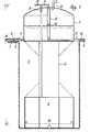
- the water storage reservoir 1 having the bottom and the top parts joined by tie rods (not shown), prevalently develops along the horizontal direction.
- Said water storage reservoir 1 rests partly on the circular top of the concrete tank 2 and partly on the base of the reservoir 4 by means of the structure 3.
- the water feeding pipe 5 is connected with the base of said reservoir 1, and a gate valve 6 is provided in said pipe.
- a branch 7 branches off from said pipe 5 upstream said gate valve 6, said branch connecting the water feeding to the tank 2.
- a gate valve 8 is provided in said branch 7.
- a water outlet pipe 9 is provided on the other side of the reservoir 1 again at its base, the gate valve 10 being mounted in said pipe.
- the top of the reservoir 1 and that of the reservoir 4 are connected through the pipe 11, which also includes a gate valve 12.
- the pipe 11 is connected with the pipe 13, whose ends are frustum shaped and it bears side holes at its upper and lower parts.
- a floating 14 is provided inside said pipe 13, the floating closing said pipe in the upper position when the reservoir 1 is full and in the lower position when it is empty.
- a previously calibrated valve 15 is provided at the top of the reservoir 1 for the damping of water hammer.
- the opening 16 in the lower part of the reservoir 14 connects said reservoir and the tank 2.
- An overflow 17 is finally provided at the top of the tank 2 for controlling the water level in the same.
- both the gate valves 6 and 10 are closed whereas the gate valve 12 is open.
- the gate valve 12 is opened for filling the tank 2 up to a level such that the empty volume left is equal to that of the reservoir 4 and next the gate valves 8 and 12 are closed.
- the gate valve 8 opens and it is closed again only after water flows over the point 17.
- the water level is higher than point C in the reservoir 4, so that, in order to optimize the system, air is pumped in the pipe 11 through the gate valve 12, letting water to flow over point 17 until air bubbles are seen to go out mixed with water.
- pressure PAC equivalent to the sum of the pressures of the water columns in series in the reservoir 1 and the tank 2 will be of such value as to allow the stock water contained within the reservoir 1 to flow out from the pipe 9.
- the frustum-shaped end can be obtained so that adherence in the closed position is so strong as to make it necessary to connect pipe 5 to pipe 9, below said frustum-shaped end, in order to release the floating 14, when the feeding water is back. All that occurs with no alteration of the operation of the system.
- the reservoir 1 can also be connected for service to more feeding pipes.
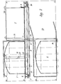
- the reservoirs 1 and 2' can be arranged either at the ground level or underground, when space is to be saved, whereas the reservoir 4 is arranged below reservoirs 1 and 2', at the end of a tunnel 23 bored purposely.
- the gate valves 12 and 8 are opened, the gate valve 8 being closed again when water from the feeding pipes 5 and 5', after filling the reservoir 4 into which it comes passing through the bottom of the reservoir 2' and through the pipe 16, has reached the level B within the pipe 11, said level corresponding to the letter E of the gauge 21.
- the gate valve 12 will be closed when water has reached level D in the pipe 11 and level F in the reservoir 2 1 as a result of the pressure of the air pumped through the valve itself.
- the pneumatic pressure given by the hydrostatic pressure P FD is conserved within the reservoir 1, such pressure being the minimum value available to the users.
- the stock water is in parallel to the normal feeding so that a double delivery is possible.
- the embodiment of Figure 2 according to the present invention can be employed for home uses arranging the reservoirs 1 and 2' below the ceiling or above it in case of cottages or of top floors, and the reservoir 4 on the floor.
- the reservoir 2 1 can also be arranged below the reservoir 1 in the form of a column. To that aim, the pipe 5' and the gate valve 10 become unnecessary and it is sufficient to joint the pipe 7 to a plug of the waterworks, placing the outlet valve 22 on the meter.
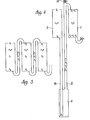
- FIGS. 3 and 4 help to understand better the principle on which the reservoir according to the present invention is based.
- the pressures of a number of vessels or reservoirs can be summed, even through said reservoirs are at reciprocally different levels, on condition that the communication means between said vessels or reservoirs contains air at the maximum pressure of the preceding vessel or reservoir.
Landscapes
- Engineering & Computer Science (AREA)
- Structural Engineering (AREA)
- Health & Medical Sciences (AREA)
- Life Sciences & Earth Sciences (AREA)
- Hydrology & Water Resources (AREA)
- Public Health (AREA)
- Water Supply & Treatment (AREA)
- Filling Or Discharging Of Gas Storage Vessels (AREA)
- Underground Structures, Protecting, Testing And Restoring Foundations (AREA)
- Sewage (AREA)
- Pipe Accessories (AREA)
Applications Claiming Priority (2)
| Application Number | Priority Date | Filing Date | Title |
|---|---|---|---|
| IT4856384 | 1984-07-13 | ||
| IT48563/84A IT1179404B (it) | 1984-07-13 | 1984-07-13 | Serbatoio di accumulazione idrica prevalentemente interrato |
Publications (2)
| Publication Number | Publication Date |
|---|---|
| EP0168361A2 true EP0168361A2 (de) | 1986-01-15 |
| EP0168361A3 EP0168361A3 (de) | 1987-03-18 |
Family
ID=11267340
Family Applications (1)
| Application Number | Title | Priority Date | Filing Date |
|---|---|---|---|
| EP85830175A Withdrawn EP0168361A3 (de) | 1984-07-13 | 1985-07-09 | Wasservorratsbehälter |
Country Status (3)
| Country | Link |
|---|---|
| US (1) | US4612951A (de) |
| EP (1) | EP0168361A3 (de) |
| IT (1) | IT1179404B (de) |
Families Citing this family (5)
| Publication number | Priority date | Publication date | Assignee | Title |
|---|---|---|---|---|
| US4962789A (en) * | 1989-11-13 | 1990-10-16 | Kenneth Benscoter | Emergency water reservoir |
| US6167899B1 (en) * | 1999-07-09 | 2001-01-02 | Chung-Min Chen | Water transporting device |
| RU2199629C2 (ru) * | 2000-12-25 | 2003-02-27 | Общество с ограниченной ответственностью "Татгазгео" | Резервуар накопитель воды |
| US7455782B2 (en) * | 2006-03-24 | 2008-11-25 | Kenneth Benscoter | Grit removal system and method for emergency water reservoir |
| JP6300770B2 (ja) * | 2015-09-10 | 2018-03-28 | 日本エンヂニヤ株式会社 | 貯水槽の緊急遮断装置 |
Family Cites Families (14)
| Publication number | Priority date | Publication date | Assignee | Title |
|---|---|---|---|---|
| US1230028A (en) * | 1917-06-12 | Edward E Rardon | Pneumatic pump. | |
| US308563A (en) * | 1884-11-25 | Waltee elam kauke | ||
| US323851A (en) * | 1885-08-04 | Vapor-burning lamp or stove | ||
| US992802A (en) * | 1909-11-22 | 1911-05-23 | Thomas B Jeffery | Apparatus for mixing and containing liquids. |
| US1486533A (en) * | 1922-06-22 | 1924-03-11 | Muffly Glenn | Water-supply system |
| US1514698A (en) * | 1923-02-15 | 1924-11-11 | James G Hampton | Water system |
| US1562693A (en) * | 1923-03-12 | 1925-11-24 | Richard E Dill | Cistern |
| US1746186A (en) * | 1927-03-16 | 1930-02-04 | Bramwell Balfour | Volumetric-displacement apparatus suitable for controlling the supply of gas for chlorinating water or similar purposes |
| US2322729A (en) * | 1941-03-22 | 1943-06-22 | Sylvania Electric Prod | Coating apparatus for gaseous discharge lamps |
| US2685887A (en) * | 1949-03-12 | 1954-08-10 | Chicago Bridge & Iron Co | Compound gravity pressure tank |
| US3301275A (en) * | 1964-02-10 | 1967-01-31 | Brady Air Controls Inc | Air retaining means for water tanks |
| US3527243A (en) * | 1969-04-15 | 1970-09-08 | Atomic Energy Commission | Liquid level control |
| SE404707B (sv) * | 1977-11-03 | 1978-10-23 | Soederstroem Gert | Vattenmagasinbrunn |
| US4185414A (en) * | 1977-11-07 | 1980-01-29 | General Electric Company | Feed regulator for nutrient film agriculture system |
-
1984
- 1984-07-13 IT IT48563/84A patent/IT1179404B/it active
-
1985
- 1985-07-09 EP EP85830175A patent/EP0168361A3/de not_active Withdrawn
- 1985-07-09 US US06/753,073 patent/US4612951A/en not_active Expired - Fee Related
Also Published As
| Publication number | Publication date |
|---|---|
| IT8448563A0 (it) | 1984-07-13 |
| US4612951A (en) | 1986-09-23 |
| IT8448563A1 (it) | 1986-01-13 |
| EP0168361A3 (de) | 1987-03-18 |
| IT1179404B (it) | 1987-09-16 |
Similar Documents
| Publication | Publication Date | Title |
|---|---|---|
| JP3771937B2 (ja) | 水の保存方法及びその装置 | |
| CN201787682U (zh) | 水蓄能稳压型精细布水系统 | |
| US3472033A (en) | Fluid storage apparatus | |
| US4612951A (en) | Water-storage reservoir | |
| CN116280852A (zh) | 一种在高压储气洞库内利用洞内气压智能控制的排水方法 | |
| US4906134A (en) | Self supporting flexible wall dams | |
| US4815494A (en) | Water tower | |
| US3422628A (en) | Offshore storage tank system | |
| CN101100847A (zh) | 分段固定孔缝泄漏闸板可拆自动报警并关闸的备用拦水坝 | |
| CN217710977U (zh) | 一种等高位连通式储水系统 | |
| CN212506687U (zh) | 自动调蓄池 | |
| CN111964870B (zh) | 一种泵房流道模拟的试验平台 | |
| CN211285727U (zh) | 一种可调节水浮力的井筒式地下空间 | |
| CN207295866U (zh) | 卫生间沉箱二次排水系统 | |
| CN224039880U (zh) | 一种基于高位消防水池的地铁车站及区间消火栓系统 | |
| JPH09111822A (ja) | 貯水装置 | |
| CN220542205U (zh) | 一种水利工程用水位监测装置 | |
| CN213390259U (zh) | 一种地下水池抗浮泄压结构 | |
| CN216999974U (zh) | 一种适于高寒地区冬季的储水装置 | |
| JPH04136332A (ja) | 雨水貯留浸透装置 | |
| CN215518989U (zh) | 装配式消防供水系统 | |
| CN214925812U (zh) | 一种混凝土加工用冷热水控制装置 | |
| EP0695256B1 (de) | Vorrichtung für kugelförmige schifftanks | |
| WO1986004628A1 (en) | Utility water distribution system | |
| Jackson | Advancements in steel storage facilities |
Legal Events
| Date | Code | Title | Description |
|---|---|---|---|
| PUAI | Public reference made under article 153(3) epc to a published international application that has entered the european phase |
Free format text: ORIGINAL CODE: 0009012 |
|
| AK | Designated contracting states |
Designated state(s): AT BE CH DE FR GB IT LI LU NL SE |
|
| PUAL | Search report despatched |
Free format text: ORIGINAL CODE: 0009013 |
|
| AK | Designated contracting states |
Kind code of ref document: A3 Designated state(s): AT BE CH DE FR GB IT LI LU NL SE |
|
| 17P | Request for examination filed |
Effective date: 19870903 |
|
| STAA | Information on the status of an ep patent application or granted ep patent |
Free format text: STATUS: THE APPLICATION HAS BEEN WITHDRAWN |
|
| 17Q | First examination report despatched |
Effective date: 19880613 |
|
| 18W | Application withdrawn |
Withdrawal date: 19880314 |