EP0167683B1 - Position fixing system - Google Patents
Position fixing system Download PDFInfo
- Publication number
- EP0167683B1 EP0167683B1 EP84303909A EP84303909A EP0167683B1 EP 0167683 B1 EP0167683 B1 EP 0167683B1 EP 84303909 A EP84303909 A EP 84303909A EP 84303909 A EP84303909 A EP 84303909A EP 0167683 B1 EP0167683 B1 EP 0167683B1
- Authority
- EP
- European Patent Office
- Prior art keywords
- receiver
- transmitters
- satellites
- frequency
- time
- Prior art date
- Legal status (The legal status is an assumption and is not a legal conclusion. Google has not performed a legal analysis and makes no representation as to the accuracy of the status listed.)
- Expired
Links
Images

Classifications
-
- G—PHYSICS
- G01—MEASURING; TESTING
- G01S—RADIO DIRECTION-FINDING; RADIO NAVIGATION; DETERMINING DISTANCE OR VELOCITY BY USE OF RADIO WAVES; LOCATING OR PRESENCE-DETECTING BY USE OF THE REFLECTION OR RERADIATION OF RADIO WAVES; ANALOGOUS ARRANGEMENTS USING OTHER WAVES
- G01S11/00—Systems for determining distance or velocity not using reflection or reradiation
- G01S11/02—Systems for determining distance or velocity not using reflection or reradiation using radio waves
- G01S11/10—Systems for determining distance or velocity not using reflection or reradiation using radio waves using Doppler effect
-
- G—PHYSICS
- G01—MEASURING; TESTING
- G01S—RADIO DIRECTION-FINDING; RADIO NAVIGATION; DETERMINING DISTANCE OR VELOCITY BY USE OF RADIO WAVES; LOCATING OR PRESENCE-DETECTING BY USE OF THE REFLECTION OR RERADIATION OF RADIO WAVES; ANALOGOUS ARRANGEMENTS USING OTHER WAVES
- G01S5/00—Position-fixing by co-ordinating two or more direction or position line determinations; Position-fixing by co-ordinating two or more distance determinations
- G01S5/02—Position-fixing by co-ordinating two or more direction or position line determinations; Position-fixing by co-ordinating two or more distance determinations using radio waves
- G01S5/0246—Position-fixing by co-ordinating two or more direction or position line determinations; Position-fixing by co-ordinating two or more distance determinations using radio waves involving frequency difference of arrival or Doppler measurements
-
- G—PHYSICS
- G01—MEASURING; TESTING
- G01S—RADIO DIRECTION-FINDING; RADIO NAVIGATION; DETERMINING DISTANCE OR VELOCITY BY USE OF RADIO WAVES; LOCATING OR PRESENCE-DETECTING BY USE OF THE REFLECTION OR RERADIATION OF RADIO WAVES; ANALOGOUS ARRANGEMENTS USING OTHER WAVES
- G01S19/00—Satellite radio beacon positioning systems; Determining position, velocity or attitude using signals transmitted by such systems
- G01S19/38—Determining a navigation solution using signals transmitted by a satellite radio beacon positioning system
- G01S19/39—Determining a navigation solution using signals transmitted by a satellite radio beacon positioning system the satellite radio beacon positioning system transmitting time-stamped messages, e.g. GPS [Global Positioning System], GLONASS [Global Orbiting Navigation Satellite System] or GALILEO
- G01S19/42—Determining position
Definitions
- the present invention concerns a method which makes it possible to obtain a position fix from the direct observation of range rate (i.e. frequency) from transmitters whose positions and velocities are known to the user.
- range rate i.e. frequency
- Ranges are measured in terms of the time taken by a radio signal to travel between transmitters and the user location. For any given point, with the additional knowledge of the location of the transmitters one can set up a set of linear simultaneous equation which computes the ranges or the equivalent time interval.
- matrix form one can write conventionally: where the vector x represents the vector of user position, u is the array of time intervals between arrival at the user and the instant of transmitting, and D is a matrix whose terms represent partial derivatives of time intervals with respect to the co-ordinates of the user.
- matrix D Assuming that matrix D is neither singular nor ill-conditioned, its inverse can be computed to produce the navigation solution where the user's position co-ordinates can be found from the measurements of ranges or time intervals. If there is no independent means of maintaining synchronisation between time at the transmitters and time at the user receiver, the dimensions of D (and D- 1 ) need to be increased by one to a square matrix of (n + 1) x (n + 1 elements) for n-dimensional navigation, and the position vector can be regarded as including time as well as geometric co-ordinates.
- Another well-known means of navigation consists of following the frequency of a radio signal transmitted from a single orbiting satellite, whose orbit and position are known at any time.
- the user observes the Doppler frequency throughout the trajectory of the satellite and, from the measurement of the time when the Doppler frequency goes through zero, and from the determination of the Doppler curve against time, he possesses all the knowledge necessary to fix his position.
- a set of simultaneous linear equations - one equation for each satellite - can then be written, expressing the Doppler offset as a function of user co-ordinates and time.
- this set of simultaneous equations can be written in terms of a (n + 1) x (n + 1) matrix (F) which, when multiplied by the (n + 1) element vector containing user position and time, yields the (n + 1) Doppler frequencies expected at the location of the user from the (n + 1) satellite transmissions (or at the (n + 1) satellites from a single transmission emanating from the user site).
- the partial differential coefficients which form the elements of the matrix describe the dependence of the Doppler offset on user co-ordinates and time; their value may be computed from the knowledge of the satellite's motion.
- Fx x v- where v- represents the (n + 1) Doppler frequencies. If F satisfies the same criteria as D, i.e. it is neither singular nor ill-conditioned, its inverse can be obtained and the user can obtain his position co-ordinates x from the measurement of Doppler frequencies v ⁇ :
- the reception of ⁇ still implies access to a precision frequency source at the user site, uncontaminated by Doppler shifts. Whilst this is not necessarily a insurmountable difficulty in all applications, it is clearly preferable to eliminate that requirement.
- the position vector x contains the co-ordinates x, y, z of the user site, T and g, where T represents the difference in synchronisation between user and satellites, and where g is the frequency offset between the satellite frequency source and the user equipment.
- T represents the difference in synchronisation between user and satellites
- g is the frequency offset between the satellite frequency source and the user equipment.
- n user-to-satellite position vectors need to be linearly independent, but that there is no restriction on satellite velocity vectors which could even be mutually parallel: one satellite may even be geo stationary.
- An example of a constellation capable of providing a minimum of 5 (or 4) satellites in view at any time on any point of the Earth is the one proposed for "GPS Navstar” or "ESA NAVSAT” - 24 (or 18) satellites uniformly spaced in 3 inclined (55°) 12 hour circular orbits - providing a continuous global 3- (or 2-) dimensional navigation service.
- the signal structure from the satellite can be made very simple. Multiple access is preferably achieved through time division, as is well established on other navigation aids like "Omega” or "HiFix".
- US-A-44.53165 discloses a navigation system comprising a plurality of satellites of which the positions and velocities are known, and a receiver for use in this navigation system. Such a receiver is arranged to receive and separate the signal emitted by the satellites, each of these signals containing a Doppler frequency shift.
- the present invention provides a receiver for use in a navigation system which includes a multiplicity of mobile transmitters of which the positions and velocities are known functions of time, the said mobile transmitters each emitting at least one signal of known frequency, the said receiver comprising means for receiving and separating the signals received from a plurality of said mobile transmitters, the received signals each containing a Doppler frequency shift corresponding to the respective radial velocity of the respective transmitter with respect to the said receiver; the receiver being characterised in that the said means are arranged to receive and separate the signals received from at least (n + 2) of said transmitters, where n represents the dimensions of a co-ordinate system with respect to which the position of said receiver is to be determined and in that it comprises further means for determining and storing values representing the Doppler frequency shifts associated respectively with said (n + 2) transmitters, and means arranged to solve (n + 2) simultaneous linear equations by which the stored Doppler frequency shifts are linked to the position co-ordinates of the receiver and to the frequency and time offsets between the transmitter
- the present invention provides a navigation system comprising at least five artificial satellites of which the positions and velocities are known functions of time, each of said satellites radiating at least one signal of known frequency, all the said known frequencies being in a known relationship, said satellites having orbits such that an unlimited number of receivers can receive said signals from a plurality of satellites, the system including at least one receiver comprising means for receiving and separating the signals received from said plurality of satellites, said received signals including a Doppler frequency shift in accordance with the velocity vector between the receiver and the respective satellite, the system being characterised in that said means are arranged to receive and separate the signals received from at least (n + 2) of said transmitters, where n represents the dimensions of a co-ordinate system with respect to which the position of said receiver is to be determined and in that it comprises further means for determining and storing the values representing said Doppler frequency shifts; and means arranged to solve (n + 2) simultaneous linear equations by which the stored Doppler frequency shifts are linked to the position co-ordinates
- Figure 1 illustrates the geometry of a known proposal for a constellation of satellites and in particular the "Navstar".
- artificial satellites encircle the Earth 1 in three 12-hour relatively inclined circular orbits, there being, for example, 8 satellites in each orbital plane. It is not necessary to employ all the satellites in the system for the purpose of the present invention and the system shown in Figure 3 employs signals from only 5 satellites.
- Figure 2 illustrates a sequence of switching signals from 5 satellites, A to E inclusive.
- Figure 2 shows a simple system in which the satellites are switched to radiate one at a time in cyclic sequence.
- the waveforms in Figure 2 are not intended to indicate the value of any particular signal but merely to show, where a pulse occurs, that the satellite is radiating at the respective time.
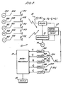
- FIG. 3 illustrates schematically 5 satellites and a mobile receiver for utilising the transmissions from the satellites.
- Satellite A includes a transmitter shown schematically as an oscillator 10A coupled via a switch S1A to an antenna 11A so as to radiate, for reception by a receiver 12 a continuous wave signal of frequency f t .
- satellite B essentially comprises oscillator 10B coupled by way of switch S1 B to antenna 11 B for radiation of the same frequency f, to the receiver 12.
- Satellites C to E inclusive are similarly arranged to radiate from respective antennas 11C to 11E.
- a switching sequence such as shown in Figure 2 is necessary and has to be controlled by suitable signals obtained, for example, from transmissions from a ground control station or otherwise in generally known manner.
- suitable signals obtained, for example, from transmissions from a ground control station or otherwise in generally known manner.
- the duration of the individual transmissions and the precise timing of them is not important and there is no requirement for any highly accurate synchronised clock.
- Signals from the various satellites are received at the receiver 12 by way of an antenna 13 which feeds one input of a mixer 14 which receives at another input a local 'oscillator signal at frequency f o from a synthesiser 15 driven by a reference oscillator 16.
- the signal received at antenna 13 is of the frequency (f t + d,) where d, is the Doppler frequency associated with the particular satellite from which signals are received at the relevant time.
- the mixer is provided in order to down convert the incoming signal prior to the measurement of its frequency.
- the output of the mixer is a frequency (f t - f o + d,) where, in successive periods of reception, d, has the values d A , d e , etc., where d A is the Doppler frequency associated with the relative movement between satellite A and the receiver 12 and so on.
- the down converted input signal is fed to one input of a digital frequency meter 17 which is clocked by the reference oscillator 16. Methods of digital frequency measurement are well-known and need not be described in any detail.
- the digital output signals from the meter 17 are fed into a switch S 2 which is synchronised with the switching of the switches S1A, S1 B etc., so as to direct the respective down converted received signal to the terminals S2A (for the signal received from satellite A), to the terminal S2B, for the down converted signal from satellite B and so on.
- the sequential output from the frequency meter 17 are transferred to individual digital stores 18A, 18B, 18C etc. Any offset in the numerical values stored in the stores is common to all five measurements.
- the stored values constitute a five dimensional vector (f 1 , f 2 , f 3 , f 4 , f s ) which is fed to a microprocessor 19.
- position co-ordinates can be obtained, for example, by matrix inversion, of a vector such as the vector obtainable from the stored digital values.
- the microprocessor is programmed in accordance with any suitable standards computer algorithm, for example, a matrix inversion algorithm, or a Gauss-Seidl elimination, to produce values for x, y, z, T and g as described above.
- a matrix inversion algorithm or a Gauss-Seidl elimination
- the technique described in the foregoing may be extended to include determination of the velocity of a receiver, especially for a surface vehicle of which the velocity vector does not have a vertical component or even an aircraft of which the vertical component of velocity is small.
- signals from two further satellites would be required.
- the foregoing embodiment is an example of a navigation system which provides at least (n + 2) transmitters of which the positions and velocities are known as a function of time each emitting at least one known frequency and all frequencies being in a known relationship so positioned that an unlimited number of passive users can obtain range rate information from n linearly independent directions which in turn can be converted into knowledge of n position co-ordinates of the user in addition to time and actual transmitted frequency.
- the user equipment can therefore attract the frequency of at least n + 2 transmitters to obtain n-dimensional position fixing, time offset and the difference between the actual transmitter frequency and the frequency source of the user without specific synchronisation with the satellite time source and without a calibrated frequency source.
- the user equipment may re-transmit signals received from transmitters as described to other users or to a ground station which can by the same technique employed by the user equipment establish in a quasi-instantaneous manner the mobile user's position and time in spite of uncertainty in the frequency shift between the received or re-transmitted frequency sets at the mobile user.
Abstract
Description
- It is well-known that a user can fix his position with respect to several transmitters at known locations through the measurement of range or elapsed time measurements. The present invention concerns a method which makes it possible to obtain a position fix from the direct observation of range rate (i.e. frequency) from transmitters whose positions and velocities are known to the user.
- Although the present invention will be particularly described with reference to a system in which the transmitters are constituted by earth-orbiting satellites, it is not intended that the invention should be restricted to such a system.
- One of the best known means of navigation makes use of radio transmitters located at known sites. Ranges are measured in terms of the time taken by a radio signal to travel between transmitters and the user location. For any given point, with the additional knowledge of the location of the transmitters one can set up a set of linear simultaneous equation which computes the ranges or the equivalent time interval. In matrix form one can write conventionally:


- Another well-known means of navigation consists of following the frequency of a radio signal transmitted from a single orbiting satellite, whose orbit and position are known at any time. The user observes the Doppler frequency throughout the trajectory of the satellite and, from the measurement of the time when the Doppler frequency goes through zero, and from the determination of the Doppler curve against time, he possesses all the knowledge necessary to fix his position.
- This is necessarily a long process depending on the orbital height. For a satellite in a 2 hour orbit, the transit time is about 20 minutes, and for a 12 hour orbit the transit time is about 5 hours. These times are too long to obtain an accurate position fix unless the question arises whether, with a small number (for example, five) of orbiting satellites, visible simultaneously to the user, it is possible for him to determine his position from a quasi-instantaneous sample of the frequencies of signals transmitted from those satellites (say within seconds), without any need for synchronisation between his time source and the satellite, and without the need for him to carry a calibrated frequency standard.
- As the satellite movements are known, their position and velocity are known at any time. Then the radial velocity of each satellite to a fixed position on Earth can be computed, and hence the Doppler frequency determined. A set of simultaneous linear equations - one equation for each satellite - can then be written, expressing the Doppler offset as a function of user co-ordinates and time. As described above, this set of simultaneous equations can be written in terms of a (n + 1) x (n + 1) matrix (F) which, when multiplied by the (n + 1) element vector containing user position and time, yields the (n + 1) Doppler frequencies expected at the location of the user from the (n + 1) satellite transmissions (or at the (n + 1) satellites from a single transmission emanating from the user site). The partial differential coefficients which form the elements of the matrix describe the dependence of the Doppler offset on user co-ordinates and time; their value may be computed from the knowledge of the satellite's motion. So again we have a matrix equation Fx x v-, where v- represents the (n + 1) Doppler frequencies. If F satisfies the same criteria as D, i.e. it is neither singular nor ill-conditioned, its inverse can be obtained and the user can obtain his position co-ordinates x from the measurement of Doppler frequencies v·:

- For the three dimensional case the position vector x contains the co-ordinates x, y, z of the user site, T and g, where T represents the difference in synchronisation between user and satellites, and where g is the frequency offset between the satellite frequency source and the user equipment. In detail, the matrix equation then represents the set of simultaneous equations:

- We have shown that it is possible to obtain at least n position co-ordinates from quasi-instantaneous frequency measurements of (n + 2) moving satellites without the need for an accurate frequency source or a synchronised clock.
- Note that n user-to-satellite position vectors need to be linearly independent, but that there is no restriction on satellite velocity vectors which could even be mutually parallel: one satellite may even be geo stationary.
- An example of a constellation capable of providing a minimum of 5 (or 4) satellites in view at any time on any point of the Earth is the one proposed for "GPS Navstar" or "ESA NAVSAT" - 24 (or 18) satellites uniformly spaced in 3 inclined (55°) 12 hour circular orbits - providing a continuous global 3- (or 2-) dimensional navigation service.
- The signal structure from the satellite can be made very simple. Multiple access is preferably achieved through time division, as is well established on other navigation aids like "Omega" or "HiFix".
- US-A-44.53165 discloses a navigation system comprising a plurality of satellites of which the positions and velocities are known, and a receiver for use in this navigation system. Such a receiver is arranged to receive and separate the signal emitted by the satellites, each of these signals containing a Doppler frequency shift.
- In one aspect, the present invention provides a receiver for use in a navigation system which includes a multiplicity of mobile transmitters of which the positions and velocities are known functions of time, the said mobile transmitters each emitting at least one signal of known frequency, the said receiver comprising means for receiving and separating the signals received from a plurality of said mobile transmitters, the received signals each containing a Doppler frequency shift corresponding to the respective radial velocity of the respective transmitter with respect to the said receiver; the receiver being characterised in that the said means are arranged to receive and separate the signals received from at least (n + 2) of said transmitters, where n represents the dimensions of a co-ordinate system with respect to which the position of said receiver is to be determined and in that it comprises further means for determining and storing values representing the Doppler frequency shifts associated respectively with said (n + 2) transmitters, and means arranged to solve (n + 2) simultaneous linear equations by which the stored Doppler frequency shifts are linked to the position co-ordinates of the receiver and to the frequency and time offsets between the transmitters and the receiver, so as to obtain the position co-ordinates of the receiver in the said co-ordinate system.
- In another aspect, the present invention provides a navigation system comprising at least five artificial satellites of which the positions and velocities are known functions of time, each of said satellites radiating at least one signal of known frequency, all the said known frequencies being in a known relationship, said satellites having orbits such that an unlimited number of receivers can receive said signals from a plurality of satellites, the system including at least one receiver comprising means for receiving and separating the signals received from said plurality of satellites, said received signals including a Doppler frequency shift in accordance with the velocity vector between the receiver and the respective satellite, the system being characterised in that said means are arranged to receive and separate the signals received from at least (n + 2) of said transmitters, where n represents the dimensions of a co-ordinate system with respect to which the position of said receiver is to be determined and in that it comprises further means for determining and storing the values representing said Doppler frequency shifts; and means arranged to solve (n + 2) simultaneous linear equations by which the stored Doppler frequency shifts are linked to the position co-ordinates of the receiver and to the frequency and time offsets between the transmitters and the receiver, so as to convert the velocity information represented by said Doppler frequency shifts into the position co-ordinates of said receiver in said co-ordinate system.
-
- Figure 1 illustrates the geometry of a constellation of satellites;
- Figure 2 is a diagram illustrating sequential switching of satellite signals; and
- Figure 3 illustrates schematically a preferred embodiment of the signal processing components according to one embodiment of the invention.
- Figure 1 illustrates the geometry of a known proposal for a constellation of satellites and in particular the "Navstar". In this system artificial satellites encircle the Earth 1 in three 12-hour relatively inclined circular orbits, there being, for example, 8 satellites in each orbital plane. It is not necessary to employ all the satellites in the system for the purpose of the present invention and the system shown in Figure 3 employs signals from only 5 satellites.
- Figure 2 illustrates a sequence of switching signals from 5 satellites, A to E inclusive. Figure 2 shows a simple system in which the satellites are switched to radiate one at a time in cyclic sequence. The waveforms in Figure 2 are not intended to indicate the value of any particular signal but merely to show, where a pulse occurs, that the satellite is radiating at the respective time.
- Figure 3 illustrates schematically 5 satellites and a mobile receiver for utilising the transmissions from the satellites. Satellite A includes a transmitter shown schematically as an
oscillator 10A coupled via a switch S1A to anantenna 11A so as to radiate, for reception by a receiver 12 a continuous wave signal of frequency ft. In like manner satellite B essentially comprisesoscillator 10B coupled by way of switch S1 B toantenna 11 B for radiation of the same frequency f, to thereceiver 12. Satellites C to E inclusive are similarly arranged to radiate from respective antennas 11C to 11E. - In this embodiment of the invention, where the signals radiated by the satellites are all-of the same frequency, a switching sequence such as shown in Figure 2 is necessary and has to be controlled by suitable signals obtained, for example, from transmissions from a ground control station or otherwise in generally known manner. However, provided that there is no overlap between the transmissions of the signals at frequency ft from the satellite, the duration of the individual transmissions and the precise timing of them is not important and there is no requirement for any highly accurate synchronised clock.
- Signals from the various satellites are received at the
receiver 12 by way of an antenna 13 which feeds one input of amixer 14 which receives at another input a local 'oscillator signal at frequency fo from asynthesiser 15 driven by areference oscillator 16. The signal received at antenna 13 is of the frequency (ft + d,) where d, is the Doppler frequency associated with the particular satellite from which signals are received at the relevant time. The mixer is provided in order to down convert the incoming signal prior to the measurement of its frequency. Thus the output of the mixer is a frequency (ft - fo + d,) where, in successive periods of reception, d, has the values dA, de, etc., where dA is the Doppler frequency associated with the relative movement between satellite A and thereceiver 12 and so on. - The down converted input signal is fed to one input of a
digital frequency meter 17 which is clocked by thereference oscillator 16. Methods of digital frequency measurement are well-known and need not be described in any detail. The digital output signals from themeter 17 are fed into a switch S2 which is synchronised with the switching of the switches S1A, S1 B etc., so as to direct the respective down converted received signal to the terminals S2A (for the signal received from satellite A), to the terminal S2B, for the down converted signal from satellite B and so on. Thus the sequential output from thefrequency meter 17 are transferred to individualdigital stores - The stored values constitute a five dimensional vector (f1, f2, f3, f4, fs) which is fed to a
microprocessor 19. - It is shown in the foregoing that position co-ordinates can be obtained, for example, by matrix inversion, of a vector such as the vector obtainable from the stored digital values. Accordingly, the microprocessor is programmed in accordance with any suitable standards computer algorithm, for example, a matrix inversion algorithm, or a Gauss-Seidl elimination, to produce values for x, y, z, T and g as described above. Of these values the required position vector (x, y, z) is extracted and displayed in numerical or graphical form on a
display 20. - The technique described in the foregoing may be extended to include determination of the velocity of a receiver, especially for a surface vehicle of which the velocity vector does not have a vertical component or even an aircraft of which the vertical component of velocity is small. In order to solve for the two velocity components dx/dt and dy/dt, signals from two further satellites would be required.
- The foregoing embodiment is an example of a navigation system which provides at least (n + 2) transmitters of which the positions and velocities are known as a function of time each emitting at least one known frequency and all frequencies being in a known relationship so positioned that an unlimited number of passive users can obtain range rate information from n linearly independent directions which in turn can be converted into knowledge of n position co-ordinates of the user in addition to time and actual transmitted frequency. The user equipment can therefore attract the frequency of at least n + 2 transmitters to obtain n-dimensional position fixing, time offset and the difference between the actual transmitter frequency and the frequency source of the user without specific synchronisation with the satellite time source and without a calibrated frequency source. The user equipment may re-transmit signals received from transmitters as described to other users or to a ground station which can by the same technique employed by the user equipment establish in a quasi-instantaneous manner the mobile user's position and time in spite of uncertainty in the frequency shift between the received or re-transmitted frequency sets at the mobile user.
Claims (3)
Priority Applications (3)
| Application Number | Priority Date | Filing Date | Title |
|---|---|---|---|
| AT84303909T ATE46580T1 (en) | 1984-06-08 | 1984-06-08 | LOCATION MEASUREMENT ARRANGEMENT. |
| DE8484303909T DE3479835D1 (en) | 1984-06-08 | 1984-06-08 | Position fixing system |
| EP84303909A EP0167683B1 (en) | 1984-06-08 | 1984-06-08 | Position fixing system |
Applications Claiming Priority (1)
| Application Number | Priority Date | Filing Date | Title |
|---|---|---|---|
| EP84303909A EP0167683B1 (en) | 1984-06-08 | 1984-06-08 | Position fixing system |
Publications (2)
| Publication Number | Publication Date |
|---|---|
| EP0167683A1 EP0167683A1 (en) | 1986-01-15 |
| EP0167683B1 true EP0167683B1 (en) | 1989-09-20 |
Family
ID=8192657
Family Applications (1)
| Application Number | Title | Priority Date | Filing Date |
|---|---|---|---|
| EP84303909A Expired EP0167683B1 (en) | 1984-06-08 | 1984-06-08 | Position fixing system |
Country Status (3)
| Country | Link |
|---|---|
| EP (1) | EP0167683B1 (en) |
| AT (1) | ATE46580T1 (en) |
| DE (1) | DE3479835D1 (en) |
Cited By (1)
| Publication number | Priority date | Publication date | Assignee | Title |
|---|---|---|---|---|
| US20230128046A1 (en) * | 2019-02-27 | 2023-04-27 | Fujitsu Limited | Detection method and computer-readable recording medium storing detection program |
Families Citing this family (4)
| Publication number | Priority date | Publication date | Assignee | Title |
|---|---|---|---|---|
| US4754283A (en) * | 1986-06-17 | 1988-06-28 | Tracor Aerospace Austin, Inc. | Codeless GPS sonde |
| DE4026740A1 (en) * | 1990-08-24 | 1992-02-27 | Wild Heerbrugg Ag | PROCESS FOR DETERMINING THE SITUATION |
| GB2368738A (en) * | 2000-07-03 | 2002-05-08 | Robert James Ely | System for space vehicle range-rate and integrated range-rate measurements |
| DE102016212919A1 (en) | 2016-07-14 | 2018-01-18 | Continental Automotive Gmbh | Method for determining a position, control module and storage medium |
Family Cites Families (3)
| Publication number | Priority date | Publication date | Assignee | Title |
|---|---|---|---|---|
| US4232389A (en) * | 1979-04-09 | 1980-11-04 | Jmr Instruments, Inc. | Receiver for satellite navigational positioning system |
| JPS58186810A (en) * | 1982-04-26 | 1983-10-31 | Nec Corp | Device for determining for space craft velocity |
| US4453165A (en) * | 1983-01-03 | 1984-06-05 | Sperry Corporation | Differential Doppler receiver |
-
1984
- 1984-06-08 AT AT84303909T patent/ATE46580T1/en active
- 1984-06-08 EP EP84303909A patent/EP0167683B1/en not_active Expired
- 1984-06-08 DE DE8484303909T patent/DE3479835D1/en not_active Expired
Cited By (1)
| Publication number | Priority date | Publication date | Assignee | Title |
|---|---|---|---|---|
| US20230128046A1 (en) * | 2019-02-27 | 2023-04-27 | Fujitsu Limited | Detection method and computer-readable recording medium storing detection program |
Also Published As
| Publication number | Publication date |
|---|---|
| EP0167683A1 (en) | 1986-01-15 |
| ATE46580T1 (en) | 1989-10-15 |
| DE3479835D1 (en) | 1989-10-26 |
Similar Documents
| Publication | Publication Date | Title |
|---|---|---|
| US5521887A (en) | Time transfer system | |
| US7711480B2 (en) | Differential GPS corrections using virtual stations | |
| US5815114A (en) | Positioning system and method | |
| US5225842A (en) | Vehicle tracking system employing global positioning system (gps) satellites | |
| Logsdon | The Navstar global positioning system | |
| US5510797A (en) | Provision of SPS timing signals | |
| EP1901088A1 (en) | Integrated mobile-terminal navigation | |
| US5886666A (en) | Airborne pseudolite navigation system | |
| Shapiro et al. | The Viking relativity experiment | |
| US5717404A (en) | Satellite ephemeris determination system using GPS tracking techniques | |
| JPH09505664A (en) | System and method for accurate position determination using code-based carrier phase | |
| Moore et al. | GPS applications in power systems. I. Introduction to GPS | |
| RU2563972C1 (en) | Spatially distributed jamming system | |
| EP0167683B1 (en) | Position fixing system | |
| Denaro | Aerospace: Navstar: The all-purpose satellite: The military sees Navstar as a way of keeping wide-ranging forces on target, and potential civilian users are showing interest too | |
| CN101382430B (en) | Temporary continental rise navigation method and system | |
| JPS6125081A (en) | Position determining system | |
| Gupta | Application of GPS and infrared for car navigation in foggy condition to avoid accident | |
| AU713642C (en) | Positioning system and method | |
| NO842540L (en) | POSITIONING SYSTEM. | |
| HOEFENER et al. | Missile Tracking with Global Positioning System (GPS) Satellites | |
| McConnell et al. | A UNIVERSAL RANGE TIMING SYSTEM USING NAVSTAR GPS | |
| Phatak | Where on earth am I? Don’t worry, GPS satellites will guide you: 2. Mechanism and uses of GPS | |
| McConnell et al. | WSMC Approach for Using GPS to Synchronize Remote Site Timing | |
| Schmid et al. | ATS-6 satellite-to-satellite tracking and data relay experiments |
Legal Events
| Date | Code | Title | Description |
|---|---|---|---|
| PUAI | Public reference made under article 153(3) epc to a published international application that has entered the european phase |
Free format text: ORIGINAL CODE: 0009012 |
|
| AK | Designated contracting states |
Designated state(s): AT BE CH DE FR GB IT LI LU NL SE |
|
| 17P | Request for examination filed |
Effective date: 19860715 |
|
| 17Q | First examination report despatched |
Effective date: 19880218 |
|
| GRAA | (expected) grant |
Free format text: ORIGINAL CODE: 0009210 |
|
| AK | Designated contracting states |
Kind code of ref document: B1 Designated state(s): AT BE CH DE FR GB IT LI LU NL SE |
|
| PG25 | Lapsed in a contracting state [announced via postgrant information from national office to epo] |
Ref country code: SE Effective date: 19890920 Ref country code: AT Effective date: 19890920 |
|
| REF | Corresponds to: |
Ref document number: 46580 Country of ref document: AT Date of ref document: 19891015 Kind code of ref document: T |
|
| ITF | It: translation for a ep patent filed |
Owner name: JACOBACCI & PERANI S.P.A. |
|
| REF | Corresponds to: |
Ref document number: 3479835 Country of ref document: DE Date of ref document: 19891026 |
|
| ET | Fr: translation filed | ||
| PGFP | Annual fee paid to national office [announced via postgrant information from national office to epo] |
Ref country code: SE Payment date: 19900615 Year of fee payment: 7 |
|
| PG25 | Lapsed in a contracting state [announced via postgrant information from national office to epo] |
Ref country code: LU Free format text: LAPSE BECAUSE OF NON-PAYMENT OF DUE FEES Effective date: 19900630 |
|
| PGFP | Annual fee paid to national office [announced via postgrant information from national office to epo] |
Ref country code: BE Payment date: 19900709 Year of fee payment: 7 |
|
| PLBE | No opposition filed within time limit |
Free format text: ORIGINAL CODE: 0009261 |
|
| STAA | Information on the status of an ep patent application or granted ep patent |
Free format text: STATUS: NO OPPOSITION FILED WITHIN TIME LIMIT |
|
| PGFP | Annual fee paid to national office [announced via postgrant information from national office to epo] |
Ref country code: LU Payment date: 19900717 Year of fee payment: 7 |
|
| 26N | No opposition filed | ||
| ITTA | It: last paid annual fee | ||
| PG25 | Lapsed in a contracting state [announced via postgrant information from national office to epo] |
Ref country code: BE Effective date: 19910630 |
|
| PGFP | Annual fee paid to national office [announced via postgrant information from national office to epo] |
Ref country code: CH Payment date: 19910730 Year of fee payment: 8 |
|
| BERE | Be: lapsed |
Owner name: DECCA LTD Effective date: 19910630 |
|
| PGFP | Annual fee paid to national office [announced via postgrant information from national office to epo] |
Ref country code: GB Payment date: 19920505 Year of fee payment: 9 |
|
| PGFP | Annual fee paid to national office [announced via postgrant information from national office to epo] |
Ref country code: FR Payment date: 19920609 Year of fee payment: 9 |
|
| PG25 | Lapsed in a contracting state [announced via postgrant information from national office to epo] |
Ref country code: LI Effective date: 19920630 Ref country code: CH Effective date: 19920630 |
|
| PGFP | Annual fee paid to national office [announced via postgrant information from national office to epo] |
Ref country code: NL Payment date: 19920630 Year of fee payment: 9 |
|
| PGFP | Annual fee paid to national office [announced via postgrant information from national office to epo] |
Ref country code: DE Payment date: 19920702 Year of fee payment: 9 |
|
| PG25 | Lapsed in a contracting state [announced via postgrant information from national office to epo] |
Ref country code: NL Effective date: 19930101 |
|
| NLV4 | Nl: lapsed or anulled due to non-payment of the annual fee | ||
| REG | Reference to a national code |
Ref country code: CH Ref legal event code: PL |
|
| PG25 | Lapsed in a contracting state [announced via postgrant information from national office to epo] |
Ref country code: GB Effective date: 19930608 |
|
| GBPC | Gb: european patent ceased through non-payment of renewal fee |
Effective date: 19930608 |
|
| PG25 | Lapsed in a contracting state [announced via postgrant information from national office to epo] |
Ref country code: FR Effective date: 19940228 |
|
| PG25 | Lapsed in a contracting state [announced via postgrant information from national office to epo] |
Ref country code: DE Effective date: 19940301 |
|
| REG | Reference to a national code |
Ref country code: FR Ref legal event code: ST |