EP0167348A2 - Vorrichtung zum Ausrichten von Anschlusselementen für ein Bauelement mit einer integrierten Schaltung - Google Patents
Vorrichtung zum Ausrichten von Anschlusselementen für ein Bauelement mit einer integrierten Schaltung Download PDFInfo
- Publication number
- EP0167348A2 EP0167348A2 EP85304553A EP85304553A EP0167348A2 EP 0167348 A2 EP0167348 A2 EP 0167348A2 EP 85304553 A EP85304553 A EP 85304553A EP 85304553 A EP85304553 A EP 85304553A EP 0167348 A2 EP0167348 A2 EP 0167348A2
- Authority
- EP
- European Patent Office
- Prior art keywords
- arms
- holes
- plate
- terminals
- package
- Prior art date
- Legal status (The legal status is an assumption and is not a legal conclusion. Google has not performed a legal analysis and makes no representation as to the accuracy of the status listed.)
- Granted
Links
Images

Classifications
-
- H—ELECTRICITY
- H05—ELECTRIC TECHNIQUES NOT OTHERWISE PROVIDED FOR
- H05K—PRINTED CIRCUITS; CASINGS OR CONSTRUCTIONAL DETAILS OF ELECTRIC APPARATUS; MANUFACTURE OF ASSEMBLAGES OF ELECTRICAL COMPONENTS
- H05K13/00—Apparatus or processes specially adapted for manufacturing or adjusting assemblages of electric components
- H05K13/04—Mounting of components, e.g. of leadless components
- H05K13/043—Feeding one by one by other means than belts
- H05K13/0439—Feeding one by one by other means than belts incorporating means for treating the terminal leads only before insertion
Definitions
- This invention relates to mechanisms which aid in inserting integrated circuit packages (IC packages) into the holes of a printed circuit board; and more particularly, it relates to mechanisms for straightening the terminals of pin grid array IC packages prior to their insertion.
- IC packages integrated circuit packages
- a semiconductor wafer is processed by various steps that have been described in the art in order to produce a plurality of identical circuits on the wafer. After this processing is complete, the circuits are cut from the wafer and are individually mounted in respective IC packages that are generally made from plastic or ceramic.
- each package contains a plurality of input/output terminals. These terminals are connected by conductors within the package to microscopic bonding pads on the integrated circuit die. Since the terminals are much larger and stronger than the bonding pads on the integrated circuit die, they are more suitable than the bonding pads themselves for making connections to the printed circuit board.
- the terminals on an IC package gets substantially larger (i.e., exceeds fifty), it is impractical to place half of the terminals on one side of the package and half on the other because the length of the package becomes too long. Instead, the terminals are made to extend from the package in a grid-like array. This is called a pin grid array package.
- the array is square-shaped, and it has at least two rows of terminals on each of the four sides. Also, the terminals are generally quite close together (e.g., less than 0.125 inches). Thus, the outer row of terminals blocks access to all of the terminals on all of the inner rows. This makes it impossible to manipulate the inner row terminals with one's fingers, and difficult at best to manipulate them with mechanical tools while the package is being inserted into the holes of a printed circuit board. Even if just a few of the terminals are slightly bent and misaligned with their respective holes, the insertion process is a tedious, time-consuming job.
- a primary object of the invention is to provide a means for straightening all of the terminals of a pin grid array IC package prior to their insertion into a printed circuit board.
- the above object, and others are by a mechanism which has a base and a pair of spaced apart arms pivotally coupled thereto. Rollers attach to the arms to support and move a plate when the arms are pivoted.
- the plate has a first set of holes which are tapered to accept bent terminals and to straighten them when they are forced into the taper.
- a plurality of pins extend from the base between the arms and stop parallel to the plate.
- the plate has a second set of holes through which the pins move when the arms are pivoted.
- a plurality of intermeshed gears couple to the base and the arms to pivot the arms in synchronization and move the plate perpendicular to the pins which push the integrated circuit package straight out of the first set of holes.
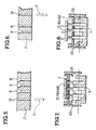
- This embodiment includes a base 11 to which a pair of spaced apart arms 12a and 12b are pivotally attached.
- a pair of shafts 13a and 13b pass through holes in base 11; and arms 12a and 12b attach to shafts 13a and 13b respectively.
- Each shaft has a cylindrical shape except for its ends which are flattened.
- Arm 12a has a pair of rectangular holes into which the flattened ends of shaft 13a fit.
- arm 12b has a pair of rectangular holes into which the flattened ends of shaft 13b fit.
- Arms 12a and 12b are coupled together by four spur gears 14a, 14b, 14c, and 14d.
- Gear 14a fits on shaft 13a between arm 12a and base 11;
- gear 14d fits onto shaft 13b between arm 12b and base 11; and gears 14b and 14c screw into base 11 between gears 14a and 14d.
- Each end of shaft 13a has a washer and a screw 15 which holds arm 12a and gear 14a in place. Another screw 15' locks gear 14a to arm 12a so that they move together. Additional screws 15 and 15' are similarly disposed on shaft 13b, arm 12b, and gear 14d.
- roller bearings 16a, 16b, 16c, and 16d screw into arm 12a; and four other roller bearings 16e, 16f, 16g, and 16h screw into arm 12b.
- These roller bearings support a flat rectangular plate 17.
- Bearings 16a, 16c, 16e, and 16g lie in one plane, and plate 17 lies on them.
- Bearings 16b, 16d, 16f, and 16h lie in another plane that is parallel to and over plate 17.
- base 11 is 5 inches long, 2-1/2 inches wide, and 1 inch high; arms 12a and 12b are 1-3/4 inches high and 2 inches long; gears 14a thru 14d are 1 inch in diameter; and plate 17 is 4-3/4 inches long, 2-1/2 inches wide, and 1/4 inch thick. All of these components are made of metal (e.g., aluminum) except for plate 17 which is made of plastic (e.g., nylon).
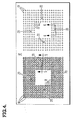
- Plate 17 has three sets of holes 18, 19, and 20. All of the holes 18 and all of the holes 19 are arranged in an identical grid-like pattern. This pattern is nineteen holes by nineteen holes on the outside, is six rows deep, and is nine holes by none holes on the inside. Various subsets of these holes correspond to the terminal pattern on several different packages.
- All of the holes 18 have a tapered upper portion and a cylindrical lower portion. Due to the tapering, the terminals of an integrated circuit package can be placed into the holes even when the terminals are bent. Then the bent terrninals can be straightened by pushing on the package to move the terminals along the taper and into the cylindrical portion of the holes.
- the sidewalls of the taper make an angle of less than 30° with the axis of the holes.
- Such a steep taper reduces the frictional force that must be overcome in order to push the IC package terminals into the holes, and it reduces wear on the tips of the terminals. This in turn enables an IC package with a large number of terminals to be easily pushed by hand into the holes 18 without scraping any conductive coating (such as gold plating) from the terminals.
- All of the holes 19 are arranged in the same pattern as the holes 18; and they are also tapered like the holes 18. However, the holes 19 are smaller than the holes 18. This enables the terminals of an IC package to be coarsely straightened via the holes 18 and then finely straightened via the holes 19.
- holes 18 and 19 respectively have a large diameter of 0.075 inches and 0.045 inches; and holes 18 and 19 respectively have a small diameter of 0.035 inches and 0.025 inches. All of the holes 18 and 19 are tapered to a depth of 0.075 inches; and they are spaced on 0.100 inch centers.
- All of the holes 20 in plate 17 are interspersed among the holes 18 and 19. These holes 20 are cylindrical and untapered; and a plurality of pins 21 extend from base 11 and fit into the holes. All of the ends of the pins 21 lie in a plane that is parallel to plate 17.
- arms 12a and 12b are pivoted pward away from base 11 until a position is reached where late 17 wedges and jams between the rollers on the top and bottom of the plate. Such a jam occurs because the radii from the pivot to the rollers on the top of plate 17 are offset by an angle of 15° with the radii to the rollers on the bottom of the plate.
- the arms 12a and 12b are pivoted to move plate 17 towards base 11. This causes the pins 21 to move through the holes 20 and push against the IC package.
- plate 17 stays perpendicular to the pins 21 as it moves. That is, whenever arm 12a is pivoted by a certain angle, the gears pivot arm 12b by the same angle; and vice versa.
- the circuit itself is in a cavity at the center of the package which is covered by a lid. This circuit and lid are not pushed on by the pins 21. Instead, the pins 21 push on the package between the surrounding terminals so that little or no mechanical stress is placed on the circuit.
- the arms 12a and 12b are L-shaped to provide a lever by which the arms are turned about their pivot point.
- the IC package terminals are removed from the holes 18 with a mechanical advantage.
- a removal force of about five pounds is required to move an IC package from plate 17. But the height of an IC package is only about one-eighth inch, and the width of one's fingers is only about one-half inch. So the pressure that must be applied by one's fingers is (5 lbs) (1/8" X 1/2" X 2) or 40 psi.
- the terminals of the IC package are removed from the holes 18, they are inserted into the holes 19 to straightem them to a finer degree. Then the bent terminals of another IC package can be inserted into the holes 18 to coarsely straighten them. Thereafter the arms 12a and 12b are pivoted to remove both IC packages from the holes 18 and 19. Then the package that was in the holes 18 is inserted into the holes 19; another package is inserted into the holes 18; etc. These operations take only a few seconds and the terminals are straightened evenly every time.
Landscapes
- Engineering & Computer Science (AREA)
- Manufacturing & Machinery (AREA)
- Microelectronics & Electronic Packaging (AREA)
- Lead Frames For Integrated Circuits (AREA)
- Wire Processing (AREA)
Applications Claiming Priority (2)
| Application Number | Priority Date | Filing Date | Title |
|---|---|---|---|
| US06/627,120 US4544003A (en) | 1984-07-02 | 1984-07-02 | Terminal straightener for an integrated circuit package |
| US627120 | 1984-07-02 |
Publications (3)
| Publication Number | Publication Date |
|---|---|
| EP0167348A2 true EP0167348A2 (de) | 1986-01-08 |
| EP0167348A3 EP0167348A3 (en) | 1988-08-24 |
| EP0167348B1 EP0167348B1 (de) | 1990-11-28 |
Family
ID=24513265
Family Applications (1)
| Application Number | Title | Priority Date | Filing Date |
|---|---|---|---|
| EP85304553A Expired EP0167348B1 (de) | 1984-07-02 | 1985-06-26 | Vorrichtung zum Ausrichten von Anschlusselementen für ein Bauelement mit einer integrierten Schaltung |
Country Status (6)
| Country | Link |
|---|---|
| US (1) | US4544003A (de) |
| EP (1) | EP0167348B1 (de) |
| JP (1) | JPS61502595A (de) |
| CA (1) | CA1233572A (de) |
| DE (1) | DE3580709D1 (de) |
| WO (1) | WO1986000548A1 (de) |
Cited By (2)
| Publication number | Priority date | Publication date | Assignee | Title |
|---|---|---|---|---|
| DE3735799A1 (de) * | 1987-10-22 | 1989-05-03 | Fraunhofer Ges Forschung | Verfahren und vorrichtung zum richten von drahtanschluessen |
| EP0316913A3 (de) * | 1987-11-16 | 1991-02-06 | OMRON Corporation | Zeitschalter |
Families Citing this family (5)
| Publication number | Priority date | Publication date | Assignee | Title |
|---|---|---|---|---|
| US4691747A (en) * | 1986-03-27 | 1987-09-08 | Advanced Micro Devices, Inc. | Controlled deformation alignment method and apparatus |
| US4945953A (en) * | 1989-05-02 | 1990-08-07 | The United States Of America As Represented By The United States Department Of Energy | Surface mount component jig |
| US5123457A (en) * | 1991-07-11 | 1992-06-23 | Ncr Corporation | Mass pin alignment tool |
| CN105396979B (zh) * | 2015-11-16 | 2017-05-10 | 如皋市大昌电子有限公司 | 一种二极管u型引脚成型装置 |
| CN110756696B (zh) * | 2019-12-06 | 2024-07-16 | 四川辰鸿电子有限公司 | 平面震动装置及具有该装置的变压器针脚校正装置 |
Family Cites Families (4)
| Publication number | Priority date | Publication date | Assignee | Title |
|---|---|---|---|---|
| US3664016A (en) * | 1970-03-24 | 1972-05-23 | Litton Systems Inc | Apparatus and method for aligning a plurality of connector mounted pins by deformation and reformation thereof |
| US3779201A (en) * | 1972-04-17 | 1973-12-18 | L Spahn | Inflatable amusement device for treading on water |
| US3779291A (en) * | 1972-05-11 | 1973-12-18 | Augat Inc | Pin straightening machine |
| US4102043A (en) * | 1978-01-17 | 1978-07-25 | Gte Sylvania Incorporated | Pin inserting apparatus |
-
1984
- 1984-07-02 US US06/627,120 patent/US4544003A/en not_active Expired - Fee Related
-
1985
- 1985-06-26 DE DE8585304553T patent/DE3580709D1/de not_active Expired - Lifetime
- 1985-06-26 EP EP85304553A patent/EP0167348B1/de not_active Expired
- 1985-06-27 CA CA000485604A patent/CA1233572A/en not_active Expired
- 1985-06-28 WO PCT/US1985/001233 patent/WO1986000548A1/en not_active Ceased
- 1985-06-28 JP JP60503054A patent/JPS61502595A/ja active Granted
Cited By (2)
| Publication number | Priority date | Publication date | Assignee | Title |
|---|---|---|---|---|
| DE3735799A1 (de) * | 1987-10-22 | 1989-05-03 | Fraunhofer Ges Forschung | Verfahren und vorrichtung zum richten von drahtanschluessen |
| EP0316913A3 (de) * | 1987-11-16 | 1991-02-06 | OMRON Corporation | Zeitschalter |
Also Published As
| Publication number | Publication date |
|---|---|
| JPS61502595A (ja) | 1986-11-13 |
| US4544003A (en) | 1985-10-01 |
| DE3580709D1 (de) | 1991-01-10 |
| EP0167348B1 (de) | 1990-11-28 |
| CA1233572A (en) | 1988-03-01 |
| JPH0350607B2 (de) | 1991-08-02 |
| EP0167348A3 (en) | 1988-08-24 |
| WO1986000548A1 (en) | 1986-01-30 |
Similar Documents
| Publication | Publication Date | Title |
|---|---|---|
| DE3789938T2 (de) | Elektrische Anordnung. | |
| US4544003A (en) | Terminal straightener for an integrated circuit package | |
| US4392301A (en) | Device for inserting and removing circuit modules with multiple leads | |
| WO1996002963A1 (en) | Electrical connector hold-down | |
| JPH0278504A (ja) | セラミック基板自動分離装置 | |
| US4461073A (en) | Device for inserting and extracting circuit modules with dual-in-line leads | |
| US4900276A (en) | Electrical connector with pin retention feature | |
| EP0289166A2 (de) | Das Geraderichten von Anschlussdrähten für eingekapselte elektronische Komponenten mit Anschlussdrähten | |
| US4943242A (en) | Zero insertion force high density connector system | |
| EP0044521A1 (de) | Verfahren und Zuführvorrichtung zum Anbringen aufeinanderfolgender Serien kleiner Gegenstände auf einer gemeinsamen Fläche | |
| US4212102A (en) | IC Socket insertion tool | |
| US4072177A (en) | Die set for forming axial leads of electrical component into hairpin lead pattern | |
| US3730234A (en) | Terminal pin straightening machine | |
| US5440803A (en) | Integrated circuit extraction tool | |
| US5617628A (en) | Integrated circuit extraction tool | |
| US4757845A (en) | Method and apparatus for bending wires | |
| US3111750A (en) | Standoff tool | |
| US5123457A (en) | Mass pin alignment tool | |
| US4470289A (en) | IC Pin adjustment tool | |
| US5319847A (en) | Method and apparatus for conditioning leads of packaged electronic devices | |
| US4515001A (en) | Variable radius lead former | |
| US4620572A (en) | Radial reform head | |
| JPH01183892A (ja) | 電子部品のリード線切断装置 | |
| JPS639680B2 (de) | ||
| WO1998051138A1 (en) | Bent lead repair tool for electronic components |
Legal Events
| Date | Code | Title | Description |
|---|---|---|---|
| PUAI | Public reference made under article 153(3) epc to a published international application that has entered the european phase |
Free format text: ORIGINAL CODE: 0009012 |
|
| 17P | Request for examination filed |
Effective date: 19850702 |
|
| AK | Designated contracting states |
Designated state(s): DE FR GB SE |
|
| RAP1 | Party data changed (applicant data changed or rights of an application transferred) |
Owner name: UNISYS CORPORATION |
|
| PUAL | Search report despatched |
Free format text: ORIGINAL CODE: 0009013 |
|
| RHK1 | Main classification (correction) |
Ipc: H05K 13/04 |
|
| AK | Designated contracting states |
Kind code of ref document: A3 Designated state(s): DE FR GB SE |
|
| 17Q | First examination report despatched |
Effective date: 19890703 |
|
| GRAA | (expected) grant |
Free format text: ORIGINAL CODE: 0009210 |
|
| AK | Designated contracting states |
Kind code of ref document: B1 Designated state(s): DE FR GB SE |
|
| ET | Fr: translation filed | ||
| REF | Corresponds to: |
Ref document number: 3580709 Country of ref document: DE Date of ref document: 19910110 |
|
| PLBE | No opposition filed within time limit |
Free format text: ORIGINAL CODE: 0009261 |
|
| STAA | Information on the status of an ep patent application or granted ep patent |
Free format text: STATUS: NO OPPOSITION FILED WITHIN TIME LIMIT |
|
| 26N | No opposition filed | ||
| PGFP | Annual fee paid to national office [announced via postgrant information from national office to epo] |
Ref country code: SE Payment date: 19920521 Year of fee payment: 8 |
|
| PGFP | Annual fee paid to national office [announced via postgrant information from national office to epo] |
Ref country code: FR Payment date: 19920606 Year of fee payment: 8 |
|
| PG25 | Lapsed in a contracting state [announced via postgrant information from national office to epo] |
Ref country code: SE Effective date: 19930627 |
|
| PG25 | Lapsed in a contracting state [announced via postgrant information from national office to epo] |
Ref country code: FR Effective date: 19940228 |
|
| REG | Reference to a national code |
Ref country code: FR Ref legal event code: ST |
|
| PGFP | Annual fee paid to national office [announced via postgrant information from national office to epo] |
Ref country code: GB Payment date: 19940511 Year of fee payment: 10 |
|
| PGFP | Annual fee paid to national office [announced via postgrant information from national office to epo] |
Ref country code: DE Payment date: 19940630 Year of fee payment: 10 |
|
| EUG | Se: european patent has lapsed |
Ref document number: 85304553.2 Effective date: 19940110 |
|
| PG25 | Lapsed in a contracting state [announced via postgrant information from national office to epo] |
Ref country code: GB Effective date: 19950626 |
|
| GBPC | Gb: european patent ceased through non-payment of renewal fee |
Effective date: 19950626 |
|
| PG25 | Lapsed in a contracting state [announced via postgrant information from national office to epo] |
Ref country code: DE Effective date: 19960301 |