EP0167283A2 - Pneumatic tyres - Google Patents
Pneumatic tyres Download PDFInfo
- Publication number
- EP0167283A2 EP0167283A2 EP85303886A EP85303886A EP0167283A2 EP 0167283 A2 EP0167283 A2 EP 0167283A2 EP 85303886 A EP85303886 A EP 85303886A EP 85303886 A EP85303886 A EP 85303886A EP 0167283 A2 EP0167283 A2 EP 0167283A2
- Authority
- EP
- European Patent Office
- Prior art keywords
- bead
- tyre
- bead core
- tyre according
- elastomeric material
- Prior art date
- Legal status (The legal status is an assumption and is not a legal conclusion. Google has not performed a legal analysis and makes no representation as to the accuracy of the status listed.)
- Granted
Links
Images
Classifications
-
- B—PERFORMING OPERATIONS; TRANSPORTING
- B60—VEHICLES IN GENERAL
- B60C—VEHICLE TYRES; TYRE INFLATION; TYRE CHANGING; CONNECTING VALVES TO INFLATABLE ELASTIC BODIES IN GENERAL; DEVICES OR ARRANGEMENTS RELATED TO TYRES
- B60C15/00—Tyre beads, e.g. ply turn-up or overlap
- B60C15/06—Flipper strips, fillers, or chafing strips and reinforcing layers for the construction of the bead
-
- B—PERFORMING OPERATIONS; TRANSPORTING
- B60—VEHICLES IN GENERAL
- B60C—VEHICLE TYRES; TYRE INFLATION; TYRE CHANGING; CONNECTING VALVES TO INFLATABLE ELASTIC BODIES IN GENERAL; DEVICES OR ARRANGEMENTS RELATED TO TYRES
- B60C15/00—Tyre beads, e.g. ply turn-up or overlap
- B60C15/02—Seating or securing beads on rims
- B60C15/024—Bead contour, e.g. lips, grooves, or ribs
Definitions
- This invention relates to pneumatic tyres and in particular to tyres having bead regions specially adapted to provide effective bead retention when used on a vehicle in a partially or fully deflated condition.
- the tyre comprises a tread portion, sidewalls and a pair of beads each containing a substantially inextensible annular reinforcement and being seated upon a bead seat one at each side of the wheel rim;
- the wheel rim including a tyre fitting well and being formed axially inward of and adjacent to at least one bead seat to provide a circumferentially extending groove which axially and radially locates at least the radially inward extremity or tip of an extended toe portion of the associated tyre bead, the said toe portion comprising elastomeric material, extending lengthwise from the annular reinforcement to the tip in a direction radially and axially .inward of the annular reinforcement, being flexible in a direction perpendicular to its length to allow tyre fitting and being substantially rigid in the direction of its length such that when an axially inward force at the tread portion is applied to the be
- the present invention provides an alternative means of improving the effectiveness of the rotating cam bead locking system which does not require a hump on the axially inner surface of the tyre bead.
- a tyre comprises a carcass and a pair of bead regions each containing a substantially inextensible bead core wherein at least one of the bead regions is provided with an axially and radially inwardly projecting extended toe portion, the extended toe portion comprising elastomeric material, being flexible perpendicular to its length and substantially rigid in the direction of its length wherein the portion of the bead region adjacent to the toe portion but radially outwards of the bead core and on the inside of the tyre carcass comprises elastomeric material having a hardness of greater than 70° Shore A.
- the said portion extends radially outwardly to a height of between 2 and 6 times the bead core cross-sectional diameter measured radially from the centre of the bead core cross-section.
- the said portion of elastomeric material comprises substantially all of the material between the carcass ply and the inner surface of the tyre bead.
- the said portion of elastomeric material more preferably has a hardness in the range 80-96° Shore A and this may be achieved by selection of compound or by the use of a filler.
- the region where the portion of elastomeric material having a hardness greater than 70° Shore A is provided may be separate from the toe although it must be adjacent thereto and it may be integral with the toe portion.
- a chafer strip of reinforcement fabric maybe provided at the outer surface 6f the said portion to provide a skin reinforcement for the portion and this chafer may be an extension of chafer strip for the toe portion when fitted.
- the chafer strip extends radially outwards of the bead core centre for 2 - 6 times the bead core cross-section diameter.
- the present invention may be combined with that of U K Patent Specification No 2 026 958 by providing also a hump at the bead core height so that both inventions combine their effects on the bead retention.
- the present invention is thought to operate by means of the bending stiffness of the elongated portion of the elastomeric material having a hardness greater than 70° Shore A acting as a lever to link the resistance of the rising cam of the toe to rotation into the tyre bead region above the bead core and thus effectively increase the torsional rigidity of the assembly. This in turn increases the tension applied to the bead core as a continuous hoop.
- the tyre is a 180/65 R 340 TD radial tyre. That is to say it is a radial tyre having bead regions designed for a TD type wheel rim.
- the tyre comprises a radial ply carcass 1, a tread 2 reinforced by a breaker structure 3 and a pair of tyre beads 4.
- Each tyre bead has a projecting toe 5 which extends radially and axially inwardly from an annular bead core 6, which in this case is a (1 x 2.2mm + 8 x 1.4mm) steel wire cable bead core.
- the carcass ply 1 is wrapped around the cable bead core 6 and extends radially outwards alongside a bead apex strip 7 in the usual way.
- the cable bead core is positioned in the bead so that the- compression under the bead when fitted to the TD wheel rim for which the tyre is intended is in the usual range of values.
- the projecting toe 5 has the usual TD cross-sectional shape as shown and in the region between the bead core 6 and the toe tip 8 is made of the usual hard rubber so that on rotation the toe acts as a cam to generate bead retaining tension in the bead core 6.
- the previously known region for.the hard rubber is between the lines A and B in Figure 2, i e from beneath the bead 6 to the level of the bead on the inside of the tyre, but in this tyre the hard rubber is continued radially outwards along the axially inner side of the bead region to the point C which is in this tyre 26mm above the centre line of the bead core.
- a cross-woven chafer strip 12 which is laid around the bead seat and toe in the usual manner has an extended portion 13 which extends radially outwards almost to the point C as shown.
- the resultant structure has the strut 9 extending beyond the 5mm cross-sectional diameter cable bead core by a distance of 26mm measured radially which provides a ratio of 26 5 5.2.
- the hardness of the material of the strut which is the same as the toe material, is in this case 92° Shore A.
- the chafer strip 12 is a cross-woven fabric available from Deering Miliken under the trade name of Takiwrap which is used untopped with rubber and cut at 45° bias. However other chafer strip fabrics may be used.
- the invention is applicable for TD tyres having all known bead core constructions and can be used with advantage in all TD tyres where rotation is used to generate bead core tensioning forces.
Abstract
Description
- This invention relates to pneumatic tyres and in particular to tyres having bead regions specially adapted to provide effective bead retention when used on a vehicle in a partially or fully deflated condition.
- Tyres of this type are disclosed in U K Patent Specification No 1 584 533 in which the tyre comprises a tread portion, sidewalls and a pair of beads each containing a substantially inextensible annular reinforcement and being seated upon a bead seat one at each side of the wheel rim; the wheel rim including a tyre fitting well and being formed axially inward of and adjacent to at least one bead seat to provide a circumferentially extending groove which axially and radially locates at least the radially inward extremity or tip of an extended toe portion of the associated tyre bead, the said toe portion comprising elastomeric material, extending lengthwise from the annular reinforcement to the tip in a direction radially and axially .inward of the annular reinforcement, being flexible in a direction perpendicular to its length to allow tyre fitting and being substantially rigid in the direction of its length such that when an axially inward force at the tread portion is applied to the bead by the tyre sidewall in the ground contacting portion of the tyre circumference, a substantially radially and axially outwardly directed force is generated at the annular reinforcement the generated force tightening the annular reinforcement and retaining the bead.
- The bead retention properties of tyres of this type are dependent on the rotating cam efficiency of the toe as it is rotated under the bead core and against the wheel rim. One attempt to improver this effeciency is disclosed in U K'Patent Publication NO 2.Q26 958 which discloses the provision of . an abutment means formed as a hump-on the axially inward face of the bead region of the tyre at the same radial height as the bead core which, on rotation of the bead, abuts the wheel rim and adds to the cam locking effect. The hump may be made of hard rubber.
- The present invention provides an alternative means of improving the effectiveness of the rotating cam bead locking system which does not require a hump on the axially inner surface of the tyre bead.
- According to the present invention a tyre comprises a carcass and a pair of bead regions each containing a substantially inextensible bead core wherein at least one of the bead regions is provided with an axially and radially inwardly projecting extended toe portion, the extended toe portion comprising elastomeric material, being flexible perpendicular to its length and substantially rigid in the direction of its length wherein the portion of the bead region adjacent to the toe portion but radially outwards of the bead core and on the inside of the tyre carcass comprises elastomeric material having a hardness of greater than 70° Shore A.
- Preferably the said portion extends radially outwardly to a height of between 2 and 6 times the bead core cross-sectional diameter measured radially from the centre of the bead core cross-section. Preferably the said portion of elastomeric material comprises substantially all of the material between the carcass ply and the inner surface of the tyre bead.
- The said portion of elastomeric material more preferably has a hardness in the range 80-96° Shore A and this may be achieved by selection of compound or by the use of a filler.
- The region where the portion of elastomeric material having a hardness greater than 70° Shore A is provided may be separate from the toe although it must be adjacent thereto and it may be integral with the toe portion.
- A chafer strip of reinforcement fabric maybe provided at the outer surface 6f the said portion to provide a skin reinforcement for the portion and this chafer may be an extension of chafer strip for the toe portion when fitted. Preferably the chafer strip extends radially outwards of the bead core centre for 2 - 6 times the bead core cross-section diameter.
- As will be appreciated the present invention may be combined with that of U K Patent Specification
No 2 026 958 by providing also a hump at the bead core height so that both inventions combine their effects on the bead retention. In contrast to the invention of U KPatent Specification No 2 026 958 the present invention is thought to operate by means of the bending stiffness of the elongated portion of the elastomeric material having a hardness greater than 70° Shore A acting as a lever to link the resistance of the rising cam of the toe to rotation into the tyre bead region above the bead core and thus effectively increase the torsional rigidity of the assembly. This in turn increases the tension applied to the bead core as a continuous hoop. - Further aspects of the present invention will be apparent from the following description, by way of example only of one embodiment in conjunction with the attached diagrammatic drawings in which:-
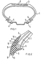
- Figure 1 is a cross-section of part of a tyre fitted to a wheel rim; and
- Figure 2 is an enlarged cross-section of one bead of the tyre of Figure 1.
- The tyre is a 180/65 R 340 TD radial tyre. That is to say it is a radial tyre having bead regions designed for a TD type wheel rim. The tyre comprises a radial ply carcass 1, a
tread 2 reinforced by abreaker structure 3 and a pair of tyre beads 4. Each tyre bead has a projectingtoe 5 which extends radially and axially inwardly from anannular bead core 6, which in this case is a (1 x 2.2mm + 8 x 1.4mm) steel wire cable bead core. The carcass ply 1 is wrapped around the cable beadcore 6 and extends radially outwards alongside a bead apex strip 7 in the usual way. The cable bead core is positioned in the bead so that the- compression under the bead when fitted to the TD wheel rim for which the tyre is intended is in the usual range of values. - The projecting
toe 5 has the usual TD cross-sectional shape as shown and in the region between thebead core 6 and the toe tip 8 is made of the usual hard rubber so that on rotation the toe acts as a cam to generate bead retaining tension in thebead core 6. The previously known region for.the hard rubber is between the lines A and B in Figure 2, i e from beneath thebead 6 to the level of the bead on the inside of the tyre, but in this tyre the hard rubber is continued radially outwards along the axially inner side of the bead region to the point C which is in this tyre 26mm above the centre line of the bead core. The radially outward continuation orstrut 9 of hard rubber is sufficiently wide to fill the space between theinner surface 10 of the tyre and the axiallyinner surface 11 of the carcass ply 1. Finally across-woven chafer strip 12 which is laid around the bead seat and toe in the usual manner has an extendedportion 13 which extends radially outwards almost to the point C as shown. - The resultant structure has the
strut 9 extending beyond the 5mm cross-sectional diameter cable bead core by a distance of 26mm measured radially which provides a ratio of 26 5 5.2. - The hardness of the material of the strut, which is the same as the toe material, is in this case 92° Shore A.
- The
chafer strip 12 is a cross-woven fabric available from Deering Miliken under the trade name of Takiwrap which is used untopped with rubber and cut at 45° bias. However other chafer strip fabrics may be used. - A tyre of the above specification was tested on a car in a fully deflated condition using the usual J turn dislodegement test and was found to be retained correctly on its wheel rim even at 45 m.p.h. (72 KPH). This made a distinct improvement over a second tyre having the
strut 9 rubber replaced by the normal inner lining material of approximately-60 - 65° Shore A hardness which dislodged on the same car in the same J turn test at 25 m.p.h. (40 KPH). - The invention is applicable for TD tyres having all known bead core constructions and can be used with advantage in all TD tyres where rotation is used to generate bead core tensioning forces.
- Materials other than the 92° Shore A hard material described may be used for the strut and hardness greater than 70° Shore A have been found to give improved bead retention.
Claims (9)
Applications Claiming Priority (2)
| Application Number | Priority Date | Filing Date | Title |
|---|---|---|---|
| GB848416529A GB8416529D0 (en) | 1984-06-28 | 1984-06-28 | Pneumatic tyres |
| GB8416529 | 1984-06-28 |
Publications (3)
| Publication Number | Publication Date |
|---|---|
| EP0167283A2 true EP0167283A2 (en) | 1986-01-08 |
| EP0167283A3 EP0167283A3 (en) | 1987-02-04 |
| EP0167283B1 EP0167283B1 (en) | 1989-08-16 |
Family
ID=10563137
Family Applications (1)
| Application Number | Title | Priority Date | Filing Date |
|---|---|---|---|
| EP19850303886 Expired EP0167283B1 (en) | 1984-06-28 | 1985-06-03 | Pneumatic tyres |
Country Status (5)
| Country | Link |
|---|---|
| EP (1) | EP0167283B1 (en) |
| JP (1) | JPS6118507A (en) |
| AU (1) | AU568710B2 (en) |
| DE (1) | DE3572329D1 (en) |
| GB (1) | GB8416529D0 (en) |
Cited By (6)
| Publication number | Priority date | Publication date | Assignee | Title |
|---|---|---|---|---|
| US4794968A (en) * | 1986-07-16 | 1989-01-03 | S P Tyres U K Limited | Tires |
| EP0434206A2 (en) * | 1989-11-17 | 1991-06-26 | Sumitomo Rubber Industries Limited | Tyre and wheel rim assembly |
| US5058649A (en) * | 1990-07-25 | 1991-10-22 | The Goodyear Tire & Rubber Company | Pneumatic tire comprising a pentagonal bead core |
| EP0498214A1 (en) * | 1991-02-08 | 1992-08-12 | Compagnie Generale Des Etablissements Michelin-Michelin & Cie | Rim-tyre combination which retains the tyre heads |
| EP0881104A1 (en) * | 1997-05-30 | 1998-12-02 | Compagnie Générale des Etablissements MICHELIN-MICHELIN & CIE | Tyre with bead comprising two cores |
| WO2013041301A1 (en) * | 2011-09-21 | 2013-03-28 | Continental Reifen Deutschland Gmbh | Pneumatic vehicle tyre with a radial design |
Citations (7)
| Publication number | Priority date | Publication date | Assignee | Title |
|---|---|---|---|---|
| FR1404543A (en) * | 1964-05-19 | 1965-07-02 | Michelin & Cie | Improvement of tire casings |
| FR2023015A2 (en) * | 1968-11-12 | 1970-08-07 | Cta | Heavy vehicle pneumatic tyre |
| US4019551A (en) * | 1976-01-23 | 1977-04-26 | The Goodyear Tire & Rubber Company | Chipperless radial ply tire |
| GB1480917A (en) * | 1973-10-26 | 1977-07-27 | Nissan Motor | Safety wheel and tire assembly for a motor vehicle |
| GB2026957A (en) * | 1978-07-29 | 1980-02-13 | Dunlop Ltd | Improvements to tyre and wheel assemblies |
| GB1584553A (en) * | 1976-06-04 | 1981-02-11 | Dunlop Ltd | Tyre and wheel rim assemblies |
| EP0077161A2 (en) * | 1981-10-09 | 1983-04-20 | Dunlop Limited | A tyre |
-
1984
- 1984-06-28 GB GB848416529A patent/GB8416529D0/en active Pending
-
1985
- 1985-06-03 EP EP19850303886 patent/EP0167283B1/en not_active Expired
- 1985-06-03 DE DE8585303886T patent/DE3572329D1/en not_active Expired
- 1985-06-26 AU AU44175/85A patent/AU568710B2/en not_active Ceased
- 1985-06-27 JP JP60141473A patent/JPS6118507A/en active Pending
Patent Citations (7)
| Publication number | Priority date | Publication date | Assignee | Title |
|---|---|---|---|---|
| FR1404543A (en) * | 1964-05-19 | 1965-07-02 | Michelin & Cie | Improvement of tire casings |
| FR2023015A2 (en) * | 1968-11-12 | 1970-08-07 | Cta | Heavy vehicle pneumatic tyre |
| GB1480917A (en) * | 1973-10-26 | 1977-07-27 | Nissan Motor | Safety wheel and tire assembly for a motor vehicle |
| US4019551A (en) * | 1976-01-23 | 1977-04-26 | The Goodyear Tire & Rubber Company | Chipperless radial ply tire |
| GB1584553A (en) * | 1976-06-04 | 1981-02-11 | Dunlop Ltd | Tyre and wheel rim assemblies |
| GB2026957A (en) * | 1978-07-29 | 1980-02-13 | Dunlop Ltd | Improvements to tyre and wheel assemblies |
| EP0077161A2 (en) * | 1981-10-09 | 1983-04-20 | Dunlop Limited | A tyre |
Cited By (13)
| Publication number | Priority date | Publication date | Assignee | Title |
|---|---|---|---|---|
| US4794968A (en) * | 1986-07-16 | 1989-01-03 | S P Tyres U K Limited | Tires |
| AU597685B2 (en) * | 1986-07-16 | 1990-06-07 | Dunlop Tyres Ltd. | Improvements to tyres |
| EP0434206A2 (en) * | 1989-11-17 | 1991-06-26 | Sumitomo Rubber Industries Limited | Tyre and wheel rim assembly |
| EP0434206A3 (en) * | 1989-11-17 | 1991-09-11 | Sumitomo Rubber Industries Limited | Tyre and wheel rim assembly |
| US5065803A (en) * | 1989-11-17 | 1991-11-19 | Sumitomo Rubber Industries, Ltd. | Tire and wheel rim assembly |
| US5058649A (en) * | 1990-07-25 | 1991-10-22 | The Goodyear Tire & Rubber Company | Pneumatic tire comprising a pentagonal bead core |
| EP0498214A1 (en) * | 1991-02-08 | 1992-08-12 | Compagnie Generale Des Etablissements Michelin-Michelin & Cie | Rim-tyre combination which retains the tyre heads |
| FR2672546A1 (en) * | 1991-02-08 | 1992-08-14 | Michelin & Cie | A TIRE AND RIM ASSEMBLY FOR AVOIDING THE DISCHARGE OF TIRE SADDLES. |
| US5297606A (en) * | 1991-02-08 | 1994-03-29 | Compagnie Generale Des Etablissements Michelin - Michelin & Cie | Combination of a tire and rim for avoiding the dislodging of the beads of the tire |
| EP0881104A1 (en) * | 1997-05-30 | 1998-12-02 | Compagnie Générale des Etablissements MICHELIN-MICHELIN & CIE | Tyre with bead comprising two cores |
| FR2763894A1 (en) * | 1997-05-30 | 1998-12-04 | Michelin & Cie | TIRE ENVELOPE WITH EACH TWO RODS IN EACH BUCKLE |
| US5968296A (en) * | 1997-05-30 | 1999-10-19 | Compagnie Generale Des Etablissements Michelin - Michelin & Cie | Tire having two wires in each bead |
| WO2013041301A1 (en) * | 2011-09-21 | 2013-03-28 | Continental Reifen Deutschland Gmbh | Pneumatic vehicle tyre with a radial design |
Also Published As
| Publication number | Publication date |
|---|---|
| EP0167283A3 (en) | 1987-02-04 |
| AU568710B2 (en) | 1988-01-07 |
| DE3572329D1 (en) | 1989-09-21 |
| EP0167283B1 (en) | 1989-08-16 |
| AU4417585A (en) | 1986-01-02 |
| JPS6118507A (en) | 1986-01-27 |
| GB8416529D0 (en) | 1984-08-01 |
Similar Documents
| Publication | Publication Date | Title |
|---|---|---|
| EP0185607B1 (en) | Pneumatic tire | |
| US4580610A (en) | Tire | |
| US6622765B1 (en) | Reinforcing tire bead for a radial tire | |
| JP3476565B2 (en) | Pneumatic tires for off-road driving | |
| JPH11502166A (en) | Tire with an aspect ratio H / S of 0.6 or less | |
| HU177085B (en) | Tyre and wheel rim structure | |
| JP2001522749A (en) | Tire crown reinforcement | |
| IE43927L (en) | Radial tyre beads. | |
| EP0410673B1 (en) | A Radial tyre for heavy duty vehicles | |
| EP0103346B1 (en) | Tyre bead reinforcement | |
| US6422280B1 (en) | Heavy duty tire with specified bead design | |
| US4541467A (en) | Heavy duty pneumatic radial tires | |
| JPH10329515A (en) | Tyre for heavy load | |
| AU760462B2 (en) | Tyre for heavy vehicle | |
| EP0955186B1 (en) | Pneumatic radial tires | |
| EP0167283B1 (en) | Pneumatic tyres | |
| EP0958153B1 (en) | Heavy duty tire with specified bead design | |
| US4260006A (en) | Tire and wheel rim assemblies | |
| CN109476189B (en) | Tire with reduced weight bead area | |
| US6386256B1 (en) | Crown reinforcement for a tire | |
| US4352383A (en) | Heavy duty pneumatic radial tire | |
| AU741644B2 (en) | Wheel and tyre assembly | |
| JP2002514537A (en) | Tire crown reinforcement | |
| US6585020B2 (en) | Crown reinforcement for a radial tire | |
| EP0253568B1 (en) | Pneumatic tyre |
Legal Events
| Date | Code | Title | Description |
|---|---|---|---|
| PUAI | Public reference made under article 153(3) epc to a published international application that has entered the european phase |
Free format text: ORIGINAL CODE: 0009012 |
|
| AK | Designated contracting states |
Designated state(s): DE FR GB IT |
|
| PUAL | Search report despatched |
Free format text: ORIGINAL CODE: 0009013 |
|
| AK | Designated contracting states |
Kind code of ref document: A3 Designated state(s): DE FR GB IT |
|
| 17P | Request for examination filed |
Effective date: 19870127 |
|
| 17Q | First examination report despatched |
Effective date: 19871130 |
|
| ITF | It: translation for a ep patent filed |
Owner name: GUZZI E RAVIZZA S.R.L. |
|
| GRAA | (expected) grant |
Free format text: ORIGINAL CODE: 0009210 |
|
| AK | Designated contracting states |
Kind code of ref document: B1 Designated state(s): DE FR GB IT |
|
| REF | Corresponds to: |
Ref document number: 3572329 Country of ref document: DE Date of ref document: 19890921 |
|
| ET | Fr: translation filed | ||
| PLBE | No opposition filed within time limit |
Free format text: ORIGINAL CODE: 0009261 |
|
| STAA | Information on the status of an ep patent application or granted ep patent |
Free format text: STATUS: NO OPPOSITION FILED WITHIN TIME LIMIT |
|
| 26N | No opposition filed | ||
| ITTA | It: last paid annual fee | ||
| PGFP | Annual fee paid to national office [announced via postgrant information from national office to epo] |
Ref country code: FR Payment date: 19980320 Year of fee payment: 14 |
|
| REG | Reference to a national code |
Ref country code: GB Ref legal event code: 732E |
|
| PG25 | Lapsed in a contracting state [announced via postgrant information from national office to epo] |
Ref country code: FR Free format text: THE PATENT HAS BEEN ANNULLED BY A DECISION OF A NATIONAL AUTHORITY Effective date: 19990630 |
|
| PGFP | Annual fee paid to national office [announced via postgrant information from national office to epo] |
Ref country code: GB Payment date: 20000614 Year of fee payment: 16 |
|
| PGFP | Annual fee paid to national office [announced via postgrant information from national office to epo] |
Ref country code: DE Payment date: 20000630 Year of fee payment: 16 |
|
| REG | Reference to a national code |
Ref country code: FR Ref legal event code: ST |
|
| PG25 | Lapsed in a contracting state [announced via postgrant information from national office to epo] |
Ref country code: GB Free format text: LAPSE BECAUSE OF NON-PAYMENT OF DUE FEES Effective date: 20010603 |
|
| GBPC | Gb: european patent ceased through non-payment of renewal fee |
Effective date: 20010603 |
|
| PG25 | Lapsed in a contracting state [announced via postgrant information from national office to epo] |
Ref country code: DE Free format text: LAPSE BECAUSE OF NON-PAYMENT OF DUE FEES Effective date: 20020403 |