EP0167167A2 - Disc case - Google Patents
Disc case Download PDFInfo
- Publication number
- EP0167167A2 EP0167167A2 EP85108295A EP85108295A EP0167167A2 EP 0167167 A2 EP0167167 A2 EP 0167167A2 EP 85108295 A EP85108295 A EP 85108295A EP 85108295 A EP85108295 A EP 85108295A EP 0167167 A2 EP0167167 A2 EP 0167167A2
- Authority
- EP
- European Patent Office
- Prior art keywords
- disc
- case
- locking
- plate
- disc case
- Prior art date
- Legal status (The legal status is an assumption and is not a legal conclusion. Google has not performed a legal analysis and makes no representation as to the accuracy of the status listed.)
- Granted
Links
- 239000002184 metal Substances 0.000 claims description 4
- 230000005489 elastic deformation Effects 0.000 claims 2
- 229920003023 plastic Polymers 0.000 claims 1
- 239000004033 plastic Substances 0.000 claims 1
- 238000010276 construction Methods 0.000 description 21
- 239000003381 stabilizer Substances 0.000 description 20
- 229920003002 synthetic resin Polymers 0.000 description 14
- 239000000057 synthetic resin Substances 0.000 description 14
- 125000006850 spacer group Chemical group 0.000 description 10
- 230000002093 peripheral effect Effects 0.000 description 7
- 238000003466 welding Methods 0.000 description 5
- 239000000853 adhesive Substances 0.000 description 4
- 230000001070 adhesive effect Effects 0.000 description 4
- 230000003287 optical effect Effects 0.000 description 4
- 230000001105 regulatory effect Effects 0.000 description 2
- 230000008094 contradictory effect Effects 0.000 description 1
- 238000006073 displacement reaction Methods 0.000 description 1
- 238000004519 manufacturing process Methods 0.000 description 1
Images


Classifications
-
- G—PHYSICS
- G11—INFORMATION STORAGE
- G11B—INFORMATION STORAGE BASED ON RELATIVE MOVEMENT BETWEEN RECORD CARRIER AND TRANSDUCER
- G11B23/00—Record carriers not specific to the method of recording or reproducing; Accessories, e.g. containers, specially adapted for co-operation with the recording or reproducing apparatus ; Intermediate mediums; Apparatus or processes specially adapted for their manufacture
- G11B23/02—Containers; Storing means both adapted to cooperate with the recording or reproducing means
- G11B23/03—Containers for flat record carriers
- G11B23/0301—Details
- G11B23/0317—Containers with interchangeable record carriers
Definitions
- the present invention relates to a disc case for receiving a disc on which information data are recorded and for supporting the disc rotatably in the disc case, the disc case being able to be set into a reproducing apparatus with the disc received in the disc case; and more particularly to a locking mechanism for locking the disc case which comprises a first case member and a second case member associated with said first case member to be able to open and close with each other.
- disc case for a microfloppy disc used in relation to various office automation equipments.
- Such disc case receives a microfloppy disc so ' that the disc can not be taken out of the case.
- a disc reproducing apparatus .. may be charged with the disc case together with the disc to be reproduced. Therefore, the disc case of such construction can not have the disc replaced and is not suitable for a disc case for a compact disc of the Compact Disc Digital Audio System.
- EPC Patent Application No.85 104 427.1 a disc case constructed to receive a disc so that the disc can be replaced.
- This disc case is formed of an upper case and a lower case which can be opened and closed with each other so that, when the upper case and lower case are opened, the disc will be able to be replaced.
- Such disc case must be locked in a closed state by a locking mechanism so that the upper case and the lower case may not accidentally open, and this locking mechanism is practically required to be easy to operate for opening the case.
- a locking mechanism of such construction as is shown, for example, in Fig. 1 is known.
- This locking mechanism is a device adopted in a dry battery containing part of such portable audio device as, for example, a portable radio set, wherein an engaging part d is formed at one end of a lid c for opening and closing an opening b of a device body a, and an opening and closing operation part h consisting of an elastically deformable part f of a U-shaped cross-section having a pawl e and an operating button g are formed at the other end of the lid c so that, when the lid c is to be closed, as shown in the drawing, the engaging part d and pawl e are engaged with the edge parts of the opening b and, when the lid c is to be opened, the operating button g is moved in the direction indicated by the arrow A to disengage the pawl e from the device body a and then the operating button g will be lifted (upward) in the direction indicated by the arrow B to take
- An object of the present invention is to provide a disc case of the kind described at the beginning which is easy in the opening and closing operation, is positive in the locking operation and is simple in the structure.
- a disc case for receiving a disc on which information data are recorded and for supporting the disc rotatably in the disc case, the disc case being able to be set into a reproducing apparatus with the disc received in the disc case and receiving the disc releasably
- the disc case comprises: a first case member having a disc receiving area on its central portion; a second case member (an upper case) associated with the first case member to be able to open and close the disc receiving area; and locking means having two locking members, a first locking member of which is formed integrally on one of the first and second case members and a second locking member of which is formed integrally on the other of the first and second case members and locks said first and second case members in a closed state with the . disc receiving area closed in cooperation with the first locking member, the second locking member having an operating part which release the locking of the first and second case members when operated.
- the first case member having the disc receiving area and the second case member are to be locked together by means of locking members formed integrally with them so that the first and second case members can be easily locked and unlocked with each other and are simple in the construction.
- the disc case according to the present invention is preferably constructed in such way that said first case member consists of: a frame with a recess, which forms the disc receiving area, on its central portion; and a magazine plate applied to a surface of the frame, the magazine plate being provided with an inserting aperture through which a turntable of the reproducing apparatus for driving to rotate the disc is introduced in a region of a position corresponding to the recess of the frame, and another inserting aperture through which a reproducing head of the reproducing appratus accesses a portion of information data recorded on the disc.
- the disc case is made thinner and is made simpler in the construction.
- the disc case according to the present invention is preferably constructed in such way that, during set into the reproducing apparatus, while the disc case is fixed in position within the reproducing apparatus, the disc is driven in rotation, and the said disc case further comprises: at least a pair of holes, arranged on at least one surface of the disc case, for positioning the disc case by engaging projections arranged on the reproducing apparatus, one hole of the pair of holes being formed as a loose hole.
- the disc case is easily and positively set and locked in a predetermined position within a reproducing apparatus.
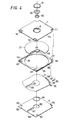
- Figs. 2 to 24 show a first embodiment of the present invention.
- Figs. 2 to 4 show the entire construction of the disc case explained hereunder.
- the disc case has as main components an upper case 1, a magazine frame 2, a shutter plate 3 and a magazine plate 4.
- the upper case 1 is a square plate-shaped body.
- This upper case 1 is integrally molded of a transparent synthetic resin, in a main wall part la of which a hole 5 is formed in its central part, tapered parts 6, 6 are formed respectively on both right and left side edges thereof, right and left cut parts 7, 7 are formed in the rear end part therof, a rear wall part 8 is formed on the rear end edge of the lower surface and right and left unlocking operating parts 10, 10 are formed in the front end part.
- the hole 5 is so formed as to steppedly reduce in the diameter in turn downward and consists of a large diameter part 5a, a medium diameter part 5b and a small diameter part 5c.
- Bosses 11, 11 for the connection with the magazine frame 2 are formed on the right and left outer end surfaces of the rear wall part 8.
- each operating part 10 consists of a bent part 10a of a U-shaped cross-section connected to the lower surface of the inner end edge of the recess 12 of the main wall part 1a, a plate part 10b extending forward from the front side upper end of this bent part 10a and an operating wall part 10c extending downward from the front end of the plate part 10b.
- a pawl 13 projecting obliquely upward is formed on the front end surface of the bent part 10a, and a hole 14 is formed in the rear end part of the plate part 10b.
- the bent part 10a is made so thin in the lower part to form a thin part 15 that the pawl 13 can be displaced forward and rearward by flexing the thin part 15.
- a stabilizer 20 is arranged within the hole 5.
- the stabilizer 20 is a member for holding a disc (compact disc) 21 and is a disc-shaped member made of a synthetic resin.
- a recess 23 to be engaged with a clamper 22 of a disc reproducing apparatus (detailed later) is formed in the central part of the upper surface
- a projection 25 to be engaged with a turntable 24 of the disc reproducing apparatus is formed in the central part of the lower surface
- a disc holding part 28 is formed on the outer peripheral edge of the lower surface and a groove 29 is formed inside this holding part.
- a sponge ring 30 is arranged by means of adhesive or the like as projected downward in the lower part within the groove 29.
- a ring 31 made of a synthetic resin for preventing the stabilizer 20 arranged within the hole 5 from being pulled out upward is fixed by means of adhesive, welding etc. within the large diameter part 5a of the hole 5.
- the stabilizer 20 is not pulled out upward as the tapered surface 26 of the engaging part 27 engages with the tapered surface 32 formed on the inner peripheral surface of the ring 31 and is not pulled out downward as the engaging part 27 engages with the step part 33 between the above mentioned medium diameter part 5b and small diameter part 5c, and is movable up and down within a range regulated by the above mentioned tapered surface 32 and step part 33 and is rotatable within the hole 5.
- the magazine frame 2 is also a square plate-shaped body and is integrally molded of a synthetic resin and easy to manufacture.
- a disc receiving recess 35 (disc receiving area) is formed in the central part of the main wall part 2a
- right and left cut parts 36, 36 are formed in the rear end part
- side wall parts 37, 37 are formed over the right and left side edges and cut parts on the upper surface, are tapered on the insides on both right and left side edges and are connected with the main wall part 2a
- a rear wall part 38 is formed in the rear end part of the main wall part 2a
- guide grooves 39, 39 are formed on both right and left side surfaces
- right and left locking parts 40, 40 are formed in the front end part
- a counterbore 41 for arranging the shutter plate 3 is formed around the disc receiving recess 35 on the lower surface
- a deep counterbore 43 deeper than this counter bore 41 and for arranging a shutter lever 42 fixed to the shutter plate 3 is formed within the counterbore 41 in the rear
- a hole 45 is formed in the end part of the deep counterbore 43 in the middle part in the right and left direction of the lower surface of the rear end part.
- the rear end part of the above mentioned side wall part 37 is positioned as separated by a fixed dimension from the side end surface of the rear wall part 38 and an engaging groove 46 for fitting the boss 11 of the upper case 1 is formed in this rear end part.
- a rack 47 to mesh with a disc case feeding pinion provided in the disc reproducing apparatus is formed on the bottom surface of one of the guide grooves 39, 39.
- the above mentioned locking part 40 is to lock the upper case 1 and magazine frame 2 with each other in cooperation with the operating part 10 of the upper case 1 and is shown in detail in Figs. 13 and 18.
- recesses 50 and holes 51 are formed in the front end part of the main wall part 2a.
- the wall part between the recess 50 and hole 51 is the locking part 40 which projects a little upward in the upper end from the upper surface of the main wall part 2a and has a pawl 52 projecting rearward on the rear surface of the upper end part as shown in Fig. 18.
- the thus constructed locking part 40 can engage with the operating part 10 as described later.
- the main wall part 2a is made a little thicker than the disc 21.
- the shutter plate 3 is a thin plate body formed of a synthetic resin and is formed to be of a shape of a circular plate body cut linearly by a predetermined dimension in the opposed outer peripheral parts, a deformed elliptic hole 54 is formed in the center part, a slot 55 connected to the hole 54 is formed in the front half part and the shutter lever 42 made of a synthetic resin is fixed to the rear end edge by means of welding or adhesive.
- the shutter lever 42 has a shaft part 56 projecting upward in the base end part, has a projection 57 projecting rearward in the intermediate part of its length and has in the tip part an operated part 58 projecting outward of the shutter plate 3.
- the magazine plate 4 is a square plate body made of a metal and contributes to the strength or rigidity of the disc case.
- This magazine plate 4 is to be fixed to the lower surface of the above mentioned magazine frame 2 and is of an outline substantially coinciding with the contour of the magazine frame 2.
- a laser beam introducing hole 61 is formed in the front half part
- right and left positioning holes 62, 62 are formed in the front end part
- fitting holes 63, 63 ... for the magazine frame 2 are formed in the four corners.
- an annular spacer 64 made of a synthetic resin is fixed by means of adhesive to the peripheral edge part of the turntable inserting aperture 60. The upper end part of the spacer 64 projects slightly above the upper surface of the magazine plate 4.
- the upper case 1 is connected to the magazine frame 2 by fitting the right and left bosses 11 in the engaging grooves 46 in the magazine frame 2 so that the upper case 1 can be rotated with the boss 11 as a center with respect to the magazine frame 2 to open and close the disc receiving recess 35.
- the disc case can be formed to be thin.
- the shutter plate 3 is arranged within the counterbore 41 while the shaft part 56 of the shutter lever 42 fixed there is fitted in the hole 45 in the magazine frame 2, and this shutter lever 42 is arranged within the deep counterbore 43 and is held within the counterbore 41 as the magazine plate 4 is fixed to the magazine frame 2 as described later.
- this shutter plate 3 is free to rotate in the directions indicated by the arrows S and T with the shaft part 56 as a center and is normally biased in the direction indicated by the arrow S by a shutter spring 65 interposed between the projection 57 of the shutter lever 42 and the magazine frame 2.
- the rotating range of the shutter plate 3 is regulated to be in a fixed range by the side wall of the counterbore 41 on the magazine frame 2.
- the shutter plate 3 has a small stroke for the opening and closing operation as its rotating center is deviated from the center of the shutter plate 3.
- the magazine plate 4 is contacted with the lower surface of the magazine frame 2 by inserting the spacer 64 in the upper end part in the hole 54 of the shutter plate 3 and is fixed to the magazine frame 2 by fastening screws not illustrated in screw holes 44 through fitting holes 63. (By the way, instead of the screw fastening, bosses may be formed on the magazine frame 2 side, may be fitted to the magazine plate 4 and then may be calked to fix the magazine plate 4.)
- the shutter plate 3 is normally biased in the direction indicated by the arrow S to close the laser beam introducing hole 61 as shown in Fig. 24.
- the operated part 58 of the shutter lever 42 will project out of the opening sidewise of the deep counterbore 43 on the magazine frame 2 and will be moved in the direction indicated by the arrow U to be in the position indicated by the solid line.
- the upper case 1 is opened with the boss 11 as a center with respcet to the magazine frame 2 and the disc 21 is received into the disc receiving recess 35 exposed outside. Then, as shown in Fig. 3, the upper case 1 is closed to close the disc receiving recess 35, the right and left unlocking operating parts 10 are engaged respectively with the locking parts 40 of the magazine frame 2 to lock the upper case 1 and magazine frame 2 with each other.
- the unlocking operating part 10 is engaged with the locking part 40, when the plate part 10b of the operating part 10 is pressed toward the locking part 40, as shown in Fig.
- the bent part 10a will come into the hole 51 in the magazine frame 2, the plate part 10b and operating wall part 10c will cover respectively the upper surface and front surface of the locking part 40, the thin part 15 of the bent part 10a will flex and the pawl 13 will engage with the pawl 52 so that the upper case 1 and magazine frame 2 will not be accidentally opened.
- the disc 21 received within will be pressed downward by the sponge ring 30 fixed to the stabilizer 20, will contact on the lower surface with the upper surface of the spacer 64 and will be held by this spacer 64 and sponge ring 30 so as not to accidentally move within the disc case.
- the operating wall parts 1 Oc of the operating parts 10 are pushed in the direction indicated by the arrow W to flex the thin parts 15 of the bent parts 10a and disengage the pawls 13 and 52 with each other and then the case 1 may be opened from the magazine frame 2.
- Such disc reproducing apparatus has a guide member for guiding the case to a predetermined playing position by engaging with the guide grooves 39, 39 of the disc case when the disc case containing the disc 21 is inserted into the apparatus, a pinion gear meshing with the rack 47 formed in one of the above mentioned guide grooves to carry the case to the predetermined position and an operating member for operating the operated part 58 of the shutter lever 42.
- the disc case has positioning pins for fixing the case in the predetermined position by engaging with the positioning holes 62, 62 of the disc case when the disc case is fed to the above mentioned predetermined position, a turntable 24 advancing into the spacer 64 to hold the disc 21 and rotating the disc 21 when it is played, a clamper 22 for pressing the stabilizer 20 downward to hold the disc 21 between the stabilizer 20 and turntable 24 and an optical head for reading the signal (information data) recorded in the disc 21 through the laser beam introducing hole 61.
- the above mentioned turntable 24 is a disc-shaped member, has a fitting wall part 71 for fitting the disc 21 in the central part of the upper surface and has a disc holding part 72 on the outer periphery of the upper surface.
- the clamper 22 is also a disc-shaped member having a projecting wall part 73 in the central part on the lower surface.
- the turntable 24 When the disc case is thus placed in the predetermined position, the turntable 24 will advance into the disc case through the spacer 64, and the fitting wall part 71 will fit into the center hole of the disc 21. At the same time, the clamper 22 will fit its projecting wall part 73 into the recess 23, and will press the stabilizer 20 downward. Thereby, the disc 21 as fitted to the fitting wall part 71 of the turntable 24 will be securely held between the disc holding part 72 of this turntable 24 and the disc holding part 28 of the stabilizer 20. By the way, at this time, the sponge ring 30 will be greatly compressed to strongly contact the disc 21.
- the turntable 24 will rotate, thereby the disc 21 will be rotated together with the clamper 22 and stabilizer 20, and the optical head will read out the signal recorded on the disc 21 through the laser beam introducing hole 61 to reproduce the disc 21.
- the above mentioned disc reproducing apparatus is an example of the apparatus for reproducing the disc by using the above described disc case.
- the disc receiving recess 35 is formed in the main wall part 2a of the magazine frame 2, and the main wall part 2a is made thicker than the disc 21, there are advantages that the space of the disc receiving area can be efficiently secured, and the entire case can be formed to be thin. Further, as the rotating center of the shutter plate 3 (the shaft part 56 of the shutter lever 42) is provided in the rear end part of the shutter plate 3 on the side opposite to the side on which the slot 55 is formed, there is an advantage that the moving stroke on the slot 55 side can be taken to be large with a small displacement of the shutter lever 42 to secure the operation of opening and closing the laser beam introducing hole 61.
- Figs. 25 to 49 show a second embodiment of the present invention.
- Figs. 25 to 27 show the entire construction of the disc case of the second embodiment.
- the disc case has as main components a lid 101, a magazine frame 102, a shutter plate 103 and a magazine plate 104.
- the lid 101 is a square plate-shaped body.
- This lid 101 integrally molded of a transparent synthetic resin and has a main wall part 101a with a hole 105 formed in its central part, a rear wall part 106 formed on the lower surface of the rear end part thereof, hook parts 107 (locking parts) and projections 108 formed on both right and left sides on the lower surface of the front end part and cut parts 109 formed in front of these hook parts 107 and projections 108.
- the hole 105 is so formed as to be smaller steppedly downward in turn to have step parts 110 and 111 within it. Holes 113,113,.. for fixing a ring 112 are formed in the step part 110 within this hole 105.
- Bosses 114, 114 for connecting with the magazine frame 102 are formed on the right and left outer end surfaces of the rear wall part 106.
- the above mentioned hook parts 107 and projections 108 form a locking device together with an unlocking operating part 115 of the magazine frame 102 (detailed later).
- the hook part 107 is so formed as to project below the main wall part 101a and has a pawl 116 in the lower end part.
- the side surface of the pawl 116 is a sloped surface 117.
- the projection 108 forms a pop-up part for moving the lid 101 upward at the time of the operation of unlocking the locking device and is so formed as to project downward on the side of the hook part 107.
- the surface of this projection 108 opposed to the hook part 107 is made a sloped surface 118.
- a stabilizer 120 is arranged within the hole 105 and is a disc-shaped member made of a synthetic resin to hold a disc (compact disc) 121.
- a sponge ring 122 contacting the disc 121 and this stabilizer 120 is fixed to the lower surface of this stabilizer 120.
- This stabilizer 120 is rotatably arranged on the step part 111 within the hole 105 and is prevented by ring 112 fixed on the step part 110 from being pulled out upward.
- the ring 112 is formed of a synthetic resin, has a plurality of projections (not illustrated) on the lower surface and is fixed to the lid 101 by inserting and heat welding these projections in respective holes 113,113,...
- the magazine frame 102 is also a square plate-shaped body, is integrally molded of a synthetic resin and can be easily manufactured.
- a disc receiving recess 125 (disc receiving area) is formed in the central part of the main wall part 102a
- a rear wall part 126 is formed on the lower surface of the rear end part
- side wall parts 127, 127 are formed in both right and left side parts
- a front wall part 128 is formed on the lower surface of the front end part
- cut parts 129, 129 are formed between the rear end parts of the side wall parts 127, 127 and the rear wall part 126
- a shutter lever supporting hole 131 is formed in the middle part of the lower surface of the rear end part
- a shutter spring receiving groove 132 is formed in one side part of the lower surface of the rear end part
- a shutter lever receiving cut part 133 is formed on the lower surface of the rear end part of one side wall part 127.
- Guide grooves 134, 134 are formed respectively on the outer surfaces of the side wall parts 127, 127, and a rack gear 135 is formed on the bottom surface of one guide groove 134.
- Supporting grooves 136 for supporting respectively the bosses 114 of the lid 101 are formed in the rear end parts of the side wall parts 127, 127.
- the contour of the unlocking operating part 115 is shown in detail in Figs. 35, 38, 39, 45 and 49. As shown in these drawings, a cut recess 140 is formed in the front end part of the main wall part 102a, and the unlocking operating part 115 is provided within this cut recess 140.
- two sets of forward extending elastically deformable arms 141a and 141b are formed respectively at a predetermined spacing on the right and left.
- An unlocking operating button 142 is formed to cover the arms 141a and 141b in the front end parts of these arms.
- a locking pawl 143 projecting sidewise is formed in the upper part of the front end of the arm 141a of the two arms.
- the contour of the arm 141a is shown in detail in Fig. 49.
- the upper surface of the locking pawl 143 is made a sloped surface 144.
- a sloped surface 145 is also formed on the surface on the side opposite to the side on which the locking pawl 143 is formed.
- the arm 141a having this sloped surface 145 together with the projection 108 of the above described lid 101 forms a pop-up part moving the lid 101 upward when the lid 101 is opened.
- the front end surface of the unlocking operating button 142 is formed to be rough so as to obtain a proper frictional force when the button is operated with a finger.
- the button 142 and arms 141a and 141b will be able to be displaced in the directions indicated by the arrows P 1 and P 2 , that is, in the directions of arranging the arms 141a and 141b by elastically deforming the arms 141a and 141b.
- a cut part 147 connected to the cut recess 1 40 is formed in the main wall part 102a so that, when the operating button 142 is moved in the direction indicated by the arrow P 11 this button 142 may not contact the main wall part 102a.
- the shutter plate 103 is a thin plate body formed of a synthetic resin, is formed to be a circular plate body cut linearly by a predetermined dimension in the opposed outer peripheral parts, and has a deformed elliptic hole 150 formed in the center part, a slot 151 connected to the hole 150 and formed in the front half part and a shutter lever 152 made of a synthetic resin and fixed by such means as of welding or adhesion to the rear end edge.
- the shutter lever 152 has an upward projecting shaft part 153 in the base end part, a projection 154 in the intermediate part in the longitudinal direction and an operated part 155 projecting toward the outside of the shutter plate 103 in the tip part.
- the magazine plate 104 is a square plate body made of a metal and contributes to the strength or rigidity of the disc case, is fixed to the lower surface of the above mentioned magazine frame 102 and is of an outline substantially coinciding with the contour of the magazine frame 102.
- a turntable inserting aperture 157 is formed in the central part
- a laser beam introducing hole 158 is formed in the front half part
- location pin inserting holes 159, 159,... and fitting holes 160, 160,... are formed in the four corners
- a front wall part 161 is formed in the front end part.
- the lid 101 is connected to the magazine frame 102 by positioning both right and left end parts of the rear wall part 106 respectively within the cut parts 129, 129 of the magazine frame 102 and fitting the bosses 114, 114 respectively within the supporting grooves 136, 136 so that it can be rotated with the bosses 114, 114 as a center with respect to the magazine frame 102 to open and close the disc receiving recess 125.
- the shutter plate 103 is arranged on the lower surface of the main wall part 102a of the magazine frame 102, while the shaft part 153 of the shutter lever 152 fixed there is fitted in the shutter lever supporting hole 131 of the magazine frame 102, and the operated part 155 of this shutter lever 152 is projected out of the cut part. 133, and is held in its position as the magazine plate 104 is fixed to the magazine frame 102 as described later.
- a spring 165 is arranged in the groove 132 of the magazine plate 102 and is engaged at one end with the projection 154 of the shutter lever and at the other end with the magazine plate 102.
- the shutter plate 103 is rotatable in the directions indicated by the arrows P 3 and P 4 with the shaft part 153 as a center and is normally biased in the direction indicated by the arrow P 3 by the biasing force of the spring 165.
- the magazine plate 104 is contacted with the lower surface of the magazine frame 102 fitted with the shutter plate 102 by inserting and welding the bosses 130b, 130b,.. formed on the magazine frame 102 respectively in the fitting holes 160.
- a spacer 166 made of a synthetic resin and shown in Fig. 27 is fixed to the upper surface of the peripheral edge part of the turntable inserting aperture 157 of the magazine plate 104.
- the location pin inserting holes 159, 159,.. of the magazine plate 104 are so positioned as to coincide respectively with the positions of the location pin inserting holes 130a, 130a,... of the magazine frame 102.
- the laser beam introducing hole 158 of the magazine plate 104 will be closed by the shutter plate 103 when the shutter- plate 103 is moved in the direction indicated by the arrow P 3 .
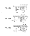
- the lid 101 In order to receive the disc 121 into the disc case of the above mentioned construction, as shown in the in Fig. 25, the lid 101 is rotated to open with the boss 114 as a center with respect to the magazine frame 102, - and the disc 121 is received into the disc receiving recess 125 exposed outside. Then, as shown in Fig. 26, the lid 101 is closed and, as shown in Fig. 49a, the pawl 116 of the hook part 107 formed on the lid 101 is engaged with the pawl 143 of the operating part 115 to lock the lid 101 and magazine frame 102 with each other.
- the lid 101 when the lid 101 is operated to be unlocked by the operating button 142, the lid 101 and magazine frame 102 will be unlocked with each other and, at the same time, the lid 101 will be opened slightly upward, that is, popped up with respect to the magazine frame 102. Therefore, in this state, if the lid 101 is gripped in the front end part and is rotated to be opened as shown in the F ig. 25, the lid 101 can be easily operated to be opened.
- the unlocking operating part 115 as the unlocking operating button 142 is supported by the elastically deformable arm 141a (141b) and all these constructions are integrally formed in the magazine frame 102, the so-called parts to be operated from outside, the power transmitting construction from there to the engaging means and the construction for guiding or supporting these members can be reasonably realized by a very simple construction and the smooth operation and positive locking of the operating button can be well satisfactory as the elastic force of the arm is utilized.
- this operating button 142 can be moved only in the directions (indicated by the arrows P 1 and P 2 ) of arranging the arms 141a and 141b, can be prevented from being moved in any other direction and can be easily moved in the predetermined directions.
- the case is so made as to be unlocked by moving the operating buttons 142, 142 in the direction indicated by the arrow P 1 .
- the case may be so made as to be unlocked by moving the buttons in the direction indicated by the arrow P 2 .
- Such disc reproducing apparatus has a guide member engaging with the guide grooves 134, 134 of the disc case to guide the case to the predetermined position for disc reproducing when the disc case containing the disc 121 is inserted into the case, a pinion gear meshing with the rack gear 135 to carry the case to the above mentioned predetermined position and an operating member operating the operated part 155 of the shutter lever 152.
- It has also location pins engaging with the location pin inserting holes 1 59 and 130a for the disc case to fix the case in the predetermined position when the disc case is fed to the above mentioned predetermined position, a turntable advancing into the turntable inserting aperture 157 to hold the disc being spaced from the spacer 166 and driven to rotate the disc 121 when it is to be reproduced, a clamper pressing the stabilizer 120 down ward to hold the disc 121 between the stabilizer 120 and turntable and an optical head for reading out the signal recorded on the disc 121 through the laser beam introducing hole 158.
- this device when the disc case is inserted by a predetermined amount into the apparatus, this device will drive the above described pinion gear to carry the disc to - the predetermined position.
- the operated part 155 of the shutter lever 152 of the disc case will contact the operating member arranged on the apparatus side, will be moved together with the case being carried and will rotate the shutter plate 103 in the direction indicated by the arrow P 4 in Fig. 25 so that the slot 151 of the shutter plate 103 will coincide with the laser beam introducing hole 158 to open it.
- the turntable When the disc case is thus placed in the predetermined position, the turntable will advance into the case through the turntable inserting aperture 157, the clamper will press the stabilizer 120 downward and the disc 121 will be held between the turntable and stabilizer 120. By the way, at this time, the sponge ring 122 will be compressed so greatly as to strongly contact the disc 121.
- the turntable will rotate, thereby the disc 121 will be rotated together with the clamper and stabilizer 120, and the optical head will read out the signal recorded on the disc 121 through the laser beam introducing hole 158 to reproduce the disc 121.
- the left side pair of holes 130a, 130a (in the Fig. 38) and corresponding holes 159, 159 for location are made into an elliptical form so that a setting operation of the disc case into the reproducing apparatus can be facilitated, and the upper side pair of holes 130a, 130a (in Fig. 38) and corresponding holes 159, 159 are disposed asymmetrically with the lower side ones so that an erroneous setting of the disc case can be inhibitted.
- the above mentioned disc reproducing apparatus is an example of the apparatus for reproducing the disc by using the above described disc case.
Landscapes
- Packaging For Recording Disks (AREA)
Abstract
Description
- The present invention relates to a disc case for receiving a disc on which information data are recorded and for supporting the disc rotatably in the disc case, the disc case being able to be set into a reproducing apparatus with the disc received in the disc case; and more particularly to a locking mechanism for locking the disc case which comprises a first case member and a second case member associated with said first case member to be able to open and close with each other.
- There is already known a disc case for a microfloppy disc used in relation to various office automation equipments. Such disc case receives a microfloppy disc so' that the disc can not be taken out of the case. Thus, when the disc is to be reproduced, a disc reproducing apparatus .. may be charged with the disc case together with the disc to be reproduced. Therefore, the disc case of such construction can not have the disc replaced and is not suitable for a disc case for a compact disc of the Compact Disc Digital Audio System.
- Therefore, the present applicant has suggested in EPC Patent Application No.85 104 427.1 a disc case constructed to receive a disc so that the disc can be replaced. This disc case is formed of an upper case and a lower case which can be opened and closed with each other so that, when the upper case and lower case are opened, the disc will be able to be replaced. Such disc case must be locked in a closed state by a locking mechanism so that the upper case and the lower case may not accidentally open, and this locking mechanism is practically required to be easy to operate for opening the case.
- There is already known such locking mechanism of this kind wherein, for example, a recess is formed in one of an upper case and a lower case, and a projection is formed in an other so that the upper case and the lower case may be locked with each other by elastically engaging the recess and the projection with each other. It is adopted, for example, in a case for storing a compact disc. In such construction, in the case of locking or unlocking it, it is necessary to elastically deform the entire case, and both the easy operation for opening the case and the - - - positive operation for locking the case are contradictory to each other and have been difficult to be compatible with each other.
- Also, a locking mechanism of such construction as is shown, for example, in Fig. 1 is known. This locking mechanism is a device adopted in a dry battery containing part of such portable audio device as, for example, a portable radio set, wherein an engaging part d is formed at one end of a lid c for opening and closing an opening b of a device body a, and an opening and closing operation part h consisting of an elastically deformable part f of a U-shaped cross-section having a pawl e and an operating button g are formed at the other end of the lid c so that, when the lid c is to be closed, as shown in the drawing, the engaging part d and pawl e are engaged with the edge parts of the opening b and, when the lid c is to be opened, the operating button g is moved in the direction indicated by the arrow A to disengage the pawl e from the device body a and then the operating button g will be lifted (upward) in the direction indicated by the arrow B to take out the lid c.
- In the conventional lid opening and closing device above mentioned, in the case of opening the lid c, the operating button g will have to be moved in the direction indicated by the arrow A and then further in the direction indicated by the arrow B and therefore there is a problem that the lid c opening operation is difficult.
- An object of the present invention is to provide a disc case of the kind described at the beginning which is easy in the opening and closing operation, is positive in the locking operation and is simple in the structure.
- This object is solved by a disc case for receiving a disc on which information data are recorded and for supporting the disc rotatably in the disc case, the disc case being able to be set into a reproducing apparatus with the disc received in the disc case and receiving the disc releasably, wherein the disc case comprises: a first case member having a disc receiving area on its central portion; a second case member (an upper case) associated with the first case member to be able to open and close the disc receiving area; and locking means having two locking members, a first locking member of which is formed integrally on one of the first and second case members and a second locking member of which is formed integrally on the other of the first and second case members and locks said first and second case members in a closed state with the . disc receiving area closed in cooperation with the first locking member, the second locking member having an operating part which release the locking of the first and second case members when operated.
- According to this invention, the first case member having the disc receiving area and the second case member are to be locked together by means of locking members formed integrally with them so that the first and second case members can be easily locked and unlocked with each other and are simple in the construction.
- The disc case according to the present invention is preferably constructed in such way that said first case member consists of: a frame with a recess, which forms the disc receiving area, on its central portion; and a magazine plate applied to a surface of the frame, the magazine plate being provided with an inserting aperture through which a turntable of the reproducing apparatus for driving to rotate the disc is introduced in a region of a position corresponding to the recess of the frame, and another inserting aperture through which a reproducing head of the reproducing appratus accesses a portion of information data recorded on the disc.
- By this construction, the disc case is made thinner and is made simpler in the construction.
- Further, the disc case according to the present invention is preferably constructed in such way that, during set into the reproducing apparatus, while the disc case is fixed in position within the reproducing apparatus, the disc is driven in rotation, and the said disc case further comprises: at least a pair of holes, arranged on at least one surface of the disc case, for positioning the disc case by engaging projections arranged on the reproducing apparatus, one hole of the pair of holes being formed as a loose hole.
- By this construction, the disc case is easily and positively set and locked in a predetermined position within a reproducing apparatus.
-
- Fig. 1 is a partly sectioned view showing an example of the conventional locking mechanism;
- Fig. 2 is a perspective view of an embodiment of the disc case according to the present invention in an opened state;
- Fig. 3 is a perspective view of the disc case in Fig. 2 in a closed state;
- Fig. 4 is an exploded perspective view of the disc case in Fig. 2,
- Fig. 5 is a plan view of the upper case-in Fig. 4;
- Fig.6 is an elevation of the upper case in Fig.4;
- Fig. 7 is a back view of the upper case in Fig. 4;
- Fig. 8 is a sectioned view along line VIII-VIII in Fig. 5;
- Fig. 9 is a sectioned view along line IX-IX in Fig. 5;
- Fig. 10 is a sectioned view along line X-X in Fig. 5;
- Fig. 11 is an enlarged view of the part indicated by the arrow P in Fig. 9;
- Fig. 12 is a bottom view of the upper case in Fig. 4;
- Fig. 13 is a plan view of the magazine frame in Fig. 4;
- Fig. 14 is an elevation of the magazine frame in Fig. 4;
- Fig. 15 is a back view of the magazine frame in Fig. 4;
- Fig. 16 is a partly side view along line XVI-XVI in Fig. 13;
- Fig. 17 is an enlarged view of the part indicated by the arrow Q in Fig. 14;
- Fig. 18 is a sectioned view along line XVIII-XVIII in Fig. 13;
- Fig. 19 is a bottom view of the magazine frame in Fig. 4;
- Fig. 20 is a partly side view along line XX-XX in Fig. 19;
- Fig. 21 is a sectioned view along line XXI-XXI in Fig. 19;
- Fig. 22 is a partly enlarged vertically sectioned view of the disc case in Fig. 2 containing a disc;
- Fig. 23 is a partly enlarged vertically sectioned view of the disc case in Fig. 2 containing a disc as set into a reproducing apparatus;
- Fig. 24 is a view showing the operation of the shutter plate in Fig. 4;
- Fig. 25 is a perspective view of another embodiment of the disc case according to the present invention in an opened state;
- Fig. 26 is a perspective view of the disc case in Fig. 25 in a closed state;
- Fig. 27 is an exploded perspective view of the disc case in Fig. 25;
- Fig.28 is a plan view of the upper case in Fig. 27;
- Fig. 29 is an elevation of the upper case in Fig. 27;
- Fig. 30 is a sectioned view along line XXX-XXX in Fig. 28;
- Fig. 31 is a bottom view of the upper case in Fig. 27;
- Fig. 32 is an elevational view along line XXXII-XXXII in Fig. 31;
- Fig. 33 is a side view along line XXXIII-XXXIII in Fig. 31;
- Fig. 34 is a sectioned view along line XXXIV- . XXXIV in Fig. 31;
- Fig. 35 is a plan view of the magazine frame in Fig. 27;
- Fig. 36 is a side view along line XXXVI-XXXVI in Fig. 35;
- Fig. 37 is a sectioned view along line XXXVII-XXXVII in Fig. 36;
- Fig. 38 is a bottom view of the magazine frame in Fig. 27;
- Fig. 39 is an elevational view along line XXXIX-XXXIX in Fig. 38;
- Fig. 40 is a back side view along line XL-XL in Fig. 38;
- Fig. 41 is a sectioned view along line XLI-XLI in Fig. 38;
- Fig. 42 is a sectioned view along line XLII-XLII in Fig. 38;
- Fig. 43 is a side view along line XLIII-XLIII in Fig. 38;
- Fig. 44 is a sectioned view along line XLIV-XLIV in Fig. 38;
- Fig. 45 is a sectioned view along line XLV-XLV in Fig. 38;
- Fig. 46 is a sectioned view along line XLVI-XLVI _. in Fig. 38;
- Fig. 47 is a sectioned view along line XLVII-XLVII in Fig. 38;
- Fig. 48 is a sectioned view along line XLVIII-XLVIII in Fig. 38;
- Fig. 49a, 49b and 49c are views for explaining the operations for unlocking and popping up the
lid 101 in Fig. 25. - The present invention shall be explained in the following with reference to the drawings on the basis of the embodiments as applied to disc cases for a compact disc of the Compact Disc Digital Audio System.
- Figs. 2 to 24 show a first embodiment of the present invention.
- Figs. 2 to 4 show the entire construction of the disc case explained hereunder. As shown in these drawings, the disc case has as main components an
upper case 1, amagazine frame 2, ashutter plate 3 and amagazine plate 4. - As shown in Figs. 5 to 12, the
upper case 1 is a square plate-shaped body. Thisupper case 1 is integrally molded of a transparent synthetic resin, in a main wall part la of which ahole 5 is formed in its central part, taperedparts left cut parts rear wall part 8 is formed on the rear end edge of the lower surface and right and left unlockingoperating parts hole 5 is so formed as to steppedly reduce in the diameter in turn downward and consists of alarge diameter part 5a, amedium diameter part 5b and asmall diameter part 5c.Bosses magazine frame 2 are formed on the right and left outer end surfaces of therear wall part 8. - The above mentioned operating
parts 10 are to lock theupper case 1 and themagazine frame 2 in a closed state in cooperation with a part of themagazine frame 2 and to unlock them when operated to unlock them and are formed within arecess 12 arranged in the front end part of themain wall part 1a. That is to say, as shown in Figs. 9 and 11, each operatingpart 10 consists of abent part 10a of a U-shaped cross-section connected to the lower surface of the inner end edge of therecess 12 of themain wall part 1a, aplate part 10b extending forward from the front side upper end of thisbent part 10a and anoperating wall part 10c extending downward from the front end of theplate part 10b. In this case apawl 13 projecting obliquely upward is formed on the front end surface of thebent part 10a, and a hole 14 is formed in the rear end part of theplate part 10b. Thebent part 10a is made so thin in the lower part to form athin part 15 that thepawl 13 can be displaced forward and rearward by flexing thethin part 15. - In the
upper case 1 formed as mentioned above, as shown in Figs. 2, 4, 22 and 23, astabilizer 20 is arranged within thehole 5. Thestabilizer 20 is a member for holding a disc (compact disc) 21 and is a disc-shaped member made of a synthetic resin. In thisstabilizer 20, arecess 23 to be engaged with aclamper 22 of a disc reproducing apparatus (detailed later) is formed in the central part of the upper surface, aprojection 25 to be engaged with aturntable 24 of the disc reproducing apparatus is formed in the central part of the lower surface, an engagingpart 27, the upper surface of which is a taperedsurface 26, is formed on the outer peripheral part, adisc holding part 28 is formed on the outer peripheral edge of the lower surface and agroove 29 is formed inside this holding part. Asponge ring 30 is arranged by means of adhesive or the like as projected downward in the lower part within thegroove 29. - A
ring 31 made of a synthetic resin for preventing thestabilizer 20 arranged within thehole 5 from being pulled out upward is fixed by means of adhesive, welding etc. within thelarge diameter part 5a of thehole 5. In this construction, thestabilizer 20 is not pulled out upward as the taperedsurface 26 of theengaging part 27 engages with the taperedsurface 32 formed on the inner peripheral surface of thering 31 and is not pulled out downward as the engagingpart 27 engages with thestep part 33 between the above mentionedmedium diameter part 5b andsmall diameter part 5c, and is movable up and down within a range regulated by the above mentioned taperedsurface 32 and steppart 33 and is rotatable within thehole 5. - As shown in Figs. 13 to 21, the
magazine frame 2 is also a square plate-shaped body and is integrally molded of a synthetic resin and easy to manufacture. In this magazine frame 2, a disc receiving recess 35 (disc receiving area) is formed in the central part of the main wall part 2a, right and left cut parts 36, 36 are formed in the rear end part, side wall parts 37, 37 are formed over the right and left side edges and cut parts on the upper surface, are tapered on the insides on both right and left side edges and are connected with the main wall part 2a, a rear wall part 38 is formed in the rear end part of the main wall part 2a, guide grooves 39, 39 are formed on both right and left side surfaces, right and left locking parts 40, 40 are formed in the front end part, a counterbore 41 for arranging the shutter plate 3 is formed around the disc receiving recess 35 on the lower surface, a deep counterbore 43 deeper than this counter bore 41 and for arranging a shutter lever 42 fixed to the shutter plate 3 is formed within the counterbore 41 in the rear end part of the lower surface, screw holes 44, 44, ... for fixing the magazine plate 4 are formed in the four corners on the lower surface and a hole 45 is formed in the end part of the deep counterbore 43 in the middle part in the right and left direction of the lower surface of the rear end part. The rear end part of the above mentionedside wall part 37 is positioned as separated by a fixed dimension from the side end surface of therear wall part 38 and an engaginggroove 46 for fitting theboss 11 of theupper case 1 is formed in this rear end part. Arack 47 to mesh with a disc case feeding pinion provided in the disc reproducing apparatus is formed on the bottom surface of one of theguide grooves - The above mentioned locking
part 40 is to lock theupper case 1 andmagazine frame 2 with each other in cooperation with the operatingpart 10 of theupper case 1 and is shown in detail in Figs. 13 and 18. As shown in these drawings, recesses 50 and holes 51 are formed in the front end part of themain wall part 2a. The wall part between therecess 50 andhole 51 is the lockingpart 40 which projects a little upward in the upper end from the upper surface of themain wall part 2a and has apawl 52 projecting rearward on the rear surface of the upper end part as shown in Fig. 18. The thus constructed lockingpart 40 can engage with the operatingpart 10 as described later. By the way, themain wall part 2a is made a little thicker than thedisc 21. - As shown in Figs. 4 and 24, the
shutter plate 3 is a thin plate body formed of a synthetic resin and is formed to be of a shape of a circular plate body cut linearly by a predetermined dimension in the opposed outer peripheral parts, a deformedelliptic hole 54 is formed in the center part, aslot 55 connected to thehole 54 is formed in the front half part and theshutter lever 42 made of a synthetic resin is fixed to the rear end edge by means of welding or adhesive. Theshutter lever 42 has ashaft part 56 projecting upward in the base end part, has aprojection 57 projecting rearward in the intermediate part of its length and has in the tip part an operatedpart 58 projecting outward of theshutter plate 3. - The
magazine plate 4 is a square plate body made of a metal and contributes to the strength or rigidity of the disc case. Thismagazine plate 4 is to be fixed to the lower surface of the above mentionedmagazine frame 2 and is of an outline substantially coinciding with the contour of themagazine frame 2. In thismagazine plate 4, as shown in Fig. 4, asturntable inserting aperture 60 is formed in the central part, a laserbeam introducing hole 61 is formed in the front half part, right and left positioning holes 62, 62 are formed in the front end part andfitting holes magazine frame 2 are formed in the four corners. In thismagazine plate 4, as shown in Figs. 4, 22 and 23, anannular spacer 64 made of a synthetic resin is fixed by means of adhesive to the peripheral edge part of theturntable inserting aperture 60. The upper end part of thespacer 64 projects slightly above the upper surface of themagazine plate 4. - The assembly of the above mentioned respective members is as follows. First, as shown in Figs. 2 to 4, the
upper case 1 is connected to themagazine frame 2 by fitting the right and leftbosses 11 in the engaginggrooves 46 in themagazine frame 2 so that theupper case 1 can be rotated with theboss 11 as a center with respect to themagazine frame 2 to open and close thedisc receiving recess 35. Thus, the disc case can be formed to be thin. - The
shutter plate 3 is arranged within thecounterbore 41 while theshaft part 56 of theshutter lever 42 fixed there is fitted in thehole 45 in themagazine frame 2, and thisshutter lever 42 is arranged within thedeep counterbore 43 and is held within thecounterbore 41 as themagazine plate 4 is fixed to themagazine frame 2 as described later. As shown in Fig. 24, thisshutter plate 3 is free to rotate in the directions indicated by the arrows S and T with theshaft part 56 as a center and is normally biased in the direction indicated by the arrow S by ashutter spring 65 interposed between theprojection 57 of theshutter lever 42 and themagazine frame 2. By the way, here the rotating range of theshutter plate 3 is regulated to be in a fixed range by the side wall of thecounterbore 41 on themagazine frame 2. Further, theshutter plate 3 has a small stroke for the opening and closing operation as its rotating center is deviated from the center of theshutter plate 3. - As shown in Figs. 22 and 23, the
magazine plate 4 is contacted with the lower surface of themagazine frame 2 by inserting thespacer 64 in the upper end part in thehole 54 of theshutter plate 3 and is fixed to themagazine frame 2 by fastening screws not illustrated in screw holes 44 through fitting holes 63. (By the way, instead of the screw fastening, bosses may be formed on themagazine frame 2 side, may be fitted to themagazine plate 4 and then may be calked to fix themagazine plate 4.) - In the above mentioned construction, the
shutter plate 3 is normally biased in the direction indicated by the arrow S to close the laserbeam introducing hole 61 as shown in Fig. 24. At this time, the operatedpart 58 of theshutter lever 42 will project out of the opening sidewise of thedeep counterbore 43 on themagazine frame 2 and will be moved in the direction indicated by the arrow U to be in the position indicated by the solid line. - In order to receive the
disc 21 into the disc case of the above mentioned construction, as shown in Fig. 2, theupper case 1 is opened with theboss 11 as a center with respcet to themagazine frame 2 and thedisc 21 is received into thedisc receiving recess 35 exposed outside. Then, as shown in Fig. 3, theupper case 1 is closed to close thedisc receiving recess 35, the right and left unlockingoperating parts 10 are engaged respectively with the lockingparts 40 of themagazine frame 2 to lock theupper case 1 andmagazine frame 2 with each other. In order to engage the unlocking operatingpart 10 with the lockingpart 40, when theplate part 10b of the operatingpart 10 is pressed toward the lockingpart 40, as shown in Fig. 11, thebent part 10a will come into thehole 51 in themagazine frame 2, theplate part 10b and operatingwall part 10c will cover respectively the upper surface and front surface of the lockingpart 40, thethin part 15 of thebent part 10a will flex and thepawl 13 will engage with thepawl 52 so that theupper case 1 andmagazine frame 2 will not be accidentally opened. - In this state, as shown in Fig. 22, the
disc 21 received within will be pressed downward by thesponge ring 30 fixed to thestabilizer 20, will contact on the lower surface with the upper surface of thespacer 64 and will be held by thisspacer 64 andsponge ring 30 so as not to accidentally move within the disc case. - Now, in order to open the disc case and take out the
disc 21, as shown in Figs. 3 and 11, the operatingwall parts 1 Oc of the operatingparts 10 are pushed in the direction indicated by the arrow W to flex thethin parts 15 of thebent parts 10a and disengage thepawls case 1 may be opened from themagazine frame 2. - The construction of the disc reproducing apparatus for reproducing the disc received in the above mentioned disc case shall be explained in the following. Such disc reproducing apparatus has a guide member for guiding the case to a predetermined playing position by engaging with the
guide grooves disc 21 is inserted into the apparatus, a pinion gear meshing with therack 47 formed in one of the above mentioned guide grooves to carry the case to the predetermined position and an operating member for operating the operatedpart 58 of theshutter lever 42. Also, it has positioning pins for fixing the case in the predetermined position by engaging with the positioning holes 62, 62 of the disc case when the disc case is fed to the above mentioned predetermined position, aturntable 24 advancing into thespacer 64 to hold thedisc 21 and rotating thedisc 21 when it is played, aclamper 22 for pressing thestabilizer 20 downward to hold thedisc 21 between thestabilizer 20 andturntable 24 and an optical head for reading the signal (information data) recorded in thedisc 21 through the laserbeam introducing hole 61. - The above mentioned
turntable 24 is a disc-shaped member, has afitting wall part 71 for fitting thedisc 21 in the central part of the upper surface and has adisc holding part 72 on the outer periphery of the upper surface. Theclamper 22 is also a disc-shaped member having a projectingwall part 73 in the central part on the lower surface. - In this apparatus, when the disc case is inserted by a predetermined amount into this apparatus, the above described pinion gear will be driven to carry the disc case in the direction X shown in Figs. 3 and 24 to the above mentioned predetermined position. In this case, the operated
part 58 of theshutter lever 42 of the disc case will contact the operating member arranged on the apparatus side and will be moved to the two-point chain line position from the solid line position in Fig. 24. Thereby, theshutter plate 3 will rotate in the direction indicated by the arrow T, and theslot 55 will coincide with the laserbeam introducing hole 61 to open thehole 61. - When the disc case is thus placed in the predetermined position, the
turntable 24 will advance into the disc case through thespacer 64, and thefitting wall part 71 will fit into the center hole of thedisc 21. At the same time, theclamper 22 will fit its projectingwall part 73 into therecess 23, and will press thestabilizer 20 downward. Thereby, thedisc 21 as fitted to thefitting wall part 71 of theturntable 24 will be securely held between thedisc holding part 72 of thisturntable 24 and thedisc holding part 28 of thestabilizer 20. By the way, at this time, thesponge ring 30 will be greatly compressed to strongly contact thedisc 21. - Here, if a playing instruction is given to the apparatus, the
turntable 24 will rotate, thereby thedisc 21 will be rotated together with theclamper 22 andstabilizer 20, and the optical head will read out the signal recorded on thedisc 21 through the laserbeam introducing hole 61 to reproduce thedisc 21. - The above mentioned disc reproducing apparatus is an example of the apparatus for reproducing the disc by using the above described disc case.
- By the way, in this embodiment, as the
disc receiving recess 35 is formed in themain wall part 2a of themagazine frame 2, and themain wall part 2a is made thicker than thedisc 21, there are advantages that the space of the disc receiving area can be efficiently secured, and the entire case can be formed to be thin. Further, as the rotating center of the shutter plate 3 (theshaft part 56 of the shutter lever 42) is provided in the rear end part of theshutter plate 3 on the side opposite to the side on which theslot 55 is formed, there is an advantage that the moving stroke on theslot 55 side can be taken to be large with a small displacement of theshutter lever 42 to secure the operation of opening and closing the laserbeam introducing hole 61. - Figs. 25 to 49 show a second embodiment of the present invention.
- Figs. 25 to 27 show the entire construction of the disc case of the second embodiment. As shown in these drawings, the disc case has as main components a
lid 101, amagazine frame 102, ashutter plate 103 and amagazine plate 104. - As shown in Figs. 28 to 34, the
lid 101 is a square plate-shaped body. Thislid 101 integrally molded of a transparent synthetic resin and has amain wall part 101a with ahole 105 formed in its central part, arear wall part 106 formed on the lower surface of the rear end part thereof, hook parts 107 (locking parts) andprojections 108 formed on both right and left sides on the lower surface of the front end part and cutparts 109 formed in front of thesehook parts 107 andprojections 108. As shown in Figs. 28 and 30, thehole 105 is so formed as to be smaller steppedly downward in turn to havestep parts ring 112 are formed in thestep part 110 within thishole 105.Bosses magazine frame 102 are formed on the right and left outer end surfaces of therear wall part 106. - The above mentioned
hook parts 107 andprojections 108 form a locking device together with an unlockingoperating part 115 of the magazine frame 102 (detailed later). As shown in Figs. 31, 32 and 49, thehook part 107 is so formed as to project below themain wall part 101a and has apawl 116 in the lower end part. The side surface of thepawl 116 is asloped surface 117. Theprojection 108 forms a pop-up part for moving thelid 101 upward at the time of the operation of unlocking the locking device and is so formed as to project downward on the side of thehook part 107. The surface of thisprojection 108 opposed to thehook part 107 is made asloped surface 118. - In the
lid 101 formed as mentioned above, as shown in Figs. 25 to 27, astabilizer 120 is arranged within thehole 105 and is a disc-shaped member made of a synthetic resin to hold a disc (compact disc) 121. Asponge ring 122 contacting thedisc 121 and thisstabilizer 120 is fixed to the lower surface of thisstabilizer 120. Thisstabilizer 120 is rotatably arranged on thestep part 111 within thehole 105 and is prevented byring 112 fixed on thestep part 110 from being pulled out upward. In this case, thering 112 is formed of a synthetic resin, has a plurality of projections (not illustrated) on the lower surface and is fixed to thelid 101 by inserting and heat welding these projections in respective holes 113,113,... - As shown in Figs. 35 to 48, the
magazine frame 102 is also a square plate-shaped body, is integrally molded of a synthetic resin and can be easily manufactured. In thismagazine frame 102, a disc receiving recess 125 (disc receiving area) is formed in the central part of themain wall part 102a, arear wall part 126 is formed on the lower surface of the rear end part,side wall parts front wall part 128 is formed on the lower surface of the front end part, cutparts side wall parts rear wall part 126, locationpin inserting holes plate fitting bosses operating parts lever supporting hole 131 is formed in the middle part of the lower surface of the rear end part, a shutterspring receiving groove 132 is formed in one side part of the lower surface of the rear end part and a shutter lever receiving cutpart 133 is formed on the lower surface of the rear end part of oneside wall part 127.Guide grooves side wall parts rack gear 135 is formed on the bottom surface of oneguide groove 134. Supportinggrooves 136 for supporting respectively thebosses 114 of thelid 101 are formed in the rear end parts of theside wall parts - The contour of the unlocking
operating part 115 is shown in detail in Figs. 35, 38, 39, 45 and 49. As shown in these drawings, acut recess 140 is formed in the front end part of themain wall part 102a, and the unlockingoperating part 115 is provided within thiscut recess 140. - That is to say, two sets of forward extending elastically
deformable arms operating button 142 is formed to cover thearms pawl 143 projecting sidewise is formed in the upper part of the front end of thearm 141a of the two arms. The contour of thearm 141a is shown in detail in Fig. 49. As shown in this drawing, the upper surface of the lockingpawl 143 is made asloped surface 144. Asloped surface 145 is also formed on the surface on the side opposite to the side on which the lockingpawl 143 is formed. Thearm 141a having this slopedsurface 145 together with theprojection 108 of the above describedlid 101 forms a pop-up part moving thelid 101 upward when thelid 101 is opened. The front end surface of the unlockingoperating button 142 is formed to be rough so as to obtain a proper frictional force when the button is operated with a finger. - In the unlocking
operating part 115 formed as mentioned above, when it is operated with a finger contac- , ted with the front surface of the unlockingoperating button 142, thebutton 142 andarms arms arms cut part 147 connected to thecut recess 1 40 is formed in themain wall part 102a so that, when theoperating button 142 is moved in the direction indicated by the arrow P11 thisbutton 142 may not contact themain wall part 102a. - As shown in Fig. 27, the
shutter plate 103 is a thin plate body formed of a synthetic resin, is formed to be a circular plate body cut linearly by a predetermined dimension in the opposed outer peripheral parts, and has a deformedelliptic hole 150 formed in the center part, aslot 151 connected to thehole 150 and formed in the front half part and ashutter lever 152 made of a synthetic resin and fixed by such means as of welding or adhesion to the rear end edge. Theshutter lever 152 has an upward projectingshaft part 153 in the base end part, aprojection 154 in the intermediate part in the longitudinal direction and an operatedpart 155 projecting toward the outside of theshutter plate 103 in the tip part. - The
magazine plate 104 is a square plate body made of a metal and contributes to the strength or rigidity of the disc case, is fixed to the lower surface of the above mentionedmagazine frame 102 and is of an outline substantially coinciding with the contour of themagazine frame 102. In thismagazine plate 104, aturntable inserting aperture 157 is formed in the central part, a laserbeam introducing hole 158 is formed in the front half part, locationpin inserting holes fitting holes front wall part 161 is formed in the front end part. - The assembly of the above mentioned respective member is as follows. First, as shown in the Figs. 25 to 27, the
lid 101 is connected to themagazine frame 102 by positioning both right and left end parts of therear wall part 106 respectively within thecut parts magazine frame 102 and fitting thebosses grooves bosses magazine frame 102 to open and close thedisc receiving recess 125. - The
shutter plate 103 is arranged on the lower surface of themain wall part 102a of themagazine frame 102, while theshaft part 153 of theshutter lever 152 fixed there is fitted in the shutterlever supporting hole 131 of themagazine frame 102, and the operatedpart 155 of thisshutter lever 152 is projected out of the cut part. 133, and is held in its position as themagazine plate 104 is fixed to themagazine frame 102 as described later. In this case, aspring 165 is arranged in thegroove 132 of themagazine plate 102 and is engaged at one end with theprojection 154 of the shutter lever and at the other end with themagazine plate 102. In this construction, as shown in Fig. 25, theshutter plate 103 is rotatable in the directions indicated by the arrows P3 and P4 with theshaft part 153 as a center and is normally biased in the direction indicated by the arrow P3 by the biasing force of thespring 165. - The
magazine plate 104 is contacted with the lower surface of themagazine frame 102 fitted with theshutter plate 102 by inserting and welding thebosses magazine frame 102 respectively in the fitting holes 160. In this case, aspacer 166 made of a synthetic resin and shown in Fig. 27 is fixed to the upper surface of the peripheral edge part of theturntable inserting aperture 157 of themagazine plate 104. In this construction, the locationpin inserting holes magazine plate 104 are so positioned as to coincide respectively with the positions of the locationpin inserting holes magazine frame 102. The laserbeam introducing hole 158 of themagazine plate 104 will be closed by theshutter plate 103 when the shutter-plate 103 is moved in the direction indicated by the arrow P3. - In order to receive the
disc 121 into the disc case of the above mentioned construction, as shown in the in Fig. 25, thelid 101 is rotated to open with theboss 114 as a center with respect to themagazine frame 102, - and thedisc 121 is received into thedisc receiving recess 125 exposed outside. Then, as shown in Fig. 26, thelid 101 is closed and, as shown in Fig. 49a, thepawl 116 of thehook part 107 formed on thelid 101 is engaged with thepawl 143 of the operatingpart 115 to lock thelid 101 andmagazine frame 102 with each other. In the case of engaging thepawl 116 withpawl 143, when thehook part 107 is lowered, thesloped surface 117 of thepawl 116 will contact thesloped surface 144 of thepawl 143 and thesloped surfaces arm 141a in the direction indicated by the arrow P1 and, when thepawl 11 6 is positioned below thepawl 143, thearm 141a will elastically return to engage thesepawls pawls lid 101 andmagazine frame 102 will not be accidentally unlocked. Here, thedisc 121 received within will be pressed downward by thesponge ring 122 and will be held between thissponge ring 122 and thespacer 166 fixed to themagazine plate 104. - Now, in order to open the disc case to take out the
disc 121, as shown in Figs. 26 and 49a, when the unlockingoperating button 142 of each locking operatingpart 115 is pressed with a finger and is moved in the direction indicated by the arrow Pi, thearms pawls lid 101 andmagazine frame 102 will be unlocked with each other. At this time, as shown in Fig. 49b, when thearm 141a moves in the direction indicated by the arrow P1, thesloped surface 145 of thearm 141a will contact thesloped surface 118 of theprojection 108 formed on thelid 101 and will guide theprojection 108 upward to move thelid 101 slightly upward. When the finger is separated from theoperating button 142, thearms sloped surface 144 formed on thepawl 143 will contact thesloped surface 117 of thepawl 116, will guide thehook part 107 to move upward and will further move thelid 101 upward. Thus, when thelid 101 is operated to be unlocked by theoperating button 142, thelid 101 andmagazine frame 102 will be unlocked with each other and, at the same time, thelid 101 will be opened slightly upward, that is, popped up with respect to themagazine frame 102. Therefore, in this state, if thelid 101 is gripped in the front end part and is rotated to be opened as shown in the Fig. 25, thelid 101 can be easily operated to be opened. In this case, in the unlockingoperating part 115, as the unlockingoperating button 142 is supported by the elasticallydeformable arm 141a (141b) and all these constructions are integrally formed in themagazine frame 102, the so-called parts to be operated from outside, the power transmitting construction from there to the engaging means and the construction for guiding or supporting these members can be reasonably realized by a very simple construction and the smooth operation and positive locking of the operating button can be well satisfactory as the elastic force of the arm is utilized. Furthermore, as thisoperating button 142 is supported by the twoarms button 142 can be moved only in the directions (indicated by the arrows P1 and P2) of arranging thearms buttons - The construction of the apparatus for reproducing the disc received in the above mentioned disc case shall be explained in the following. Such disc reproducing apparatus has a guide member engaging with the
guide grooves disc 121 is inserted into the case, a pinion gear meshing with therack gear 135 to carry the case to the above mentioned predetermined position and an operating member operating the operatedpart 155 of theshutter lever 152. It has also location pins engaging with the locationpin inserting holes 1 59 and 130a for the disc case to fix the case in the predetermined position when the disc case is fed to the above mentioned predetermined position, a turntable advancing into theturntable inserting aperture 157 to hold the disc being spaced from thespacer 166 and driven to rotate thedisc 121 when it is to be reproduced, a clamper pressing thestabilizer 120 down ward to hold thedisc 121 between thestabilizer 120 and turntable and an optical head for reading out the signal recorded on thedisc 121 through the laserbeam introducing hole 158. - For example, when the disc case is inserted by a predetermined amount into the apparatus, this device will drive the above described pinion gear to carry the disc to - the predetermined position. In such case, the operated
part 155 of theshutter lever 152 of the disc case will contact the operating member arranged on the apparatus side, will be moved together with the case being carried and will rotate theshutter plate 103 in the direction indicated by the arrow P4 in Fig. 25 so that theslot 151 of theshutter plate 103 will coincide with the laserbeam introducing hole 158 to open it. - When the disc case is thus placed in the predetermined position, the turntable will advance into the case through the
turntable inserting aperture 157, the clamper will press thestabilizer 120 downward and thedisc 121 will be held between the turntable andstabilizer 120. By the way, at this time, thesponge ring 122 will be compressed so greatly as to strongly contact thedisc 121. - Here, if a disc reproducing (playing) instruction is given to the apparatus, the turntable will rotate, thereby the
disc 121 will be rotated together with the clamper andstabilizer 120, and the optical head will read out the signal recorded on thedisc 121 through the laserbeam introducing hole 158 to reproduce thedisc 121. - It should be noted here that, in the above embodiment, the left side pair of
holes holes holes holes - By the way, the above mentioned disc reproducing apparatus is an example of the apparatus for reproducing the disc by using the above described disc case.
Claims (13)
Applications Claiming Priority (6)
| Application Number | Priority Date | Filing Date | Title |
|---|---|---|---|
| JP1984101162U JPH0713100Y2 (en) | 1984-07-04 | 1984-07-04 | Disc case |
| JP101162/84 | 1984-07-04 | ||
| JP1984137562U JPH0348780Y2 (en) | 1984-09-11 | 1984-09-11 | |
| JP137561/84 | 1984-09-11 | ||
| JP1984137561U JPH0348779Y2 (en) | 1984-09-11 | 1984-09-11 | |
| JP137562/84 | 1984-09-11 |
Publications (3)
| Publication Number | Publication Date |
|---|---|
| EP0167167A2 true EP0167167A2 (en) | 1986-01-08 |
| EP0167167A3 EP0167167A3 (en) | 1988-03-30 |
| EP0167167B1 EP0167167B1 (en) | 1992-03-04 |
Family
ID=27309403
Family Applications (1)
| Application Number | Title | Priority Date | Filing Date |
|---|---|---|---|
| EP85108295A Expired EP0167167B1 (en) | 1984-07-04 | 1985-07-04 | Disc case |
Country Status (3)
| Country | Link |
|---|---|
| US (2) | US4669078A (en) |
| EP (1) | EP0167167B1 (en) |
| DE (1) | DE3585465D1 (en) |
Cited By (9)
| Publication number | Priority date | Publication date | Assignee | Title |
|---|---|---|---|---|
| US4771890A (en) * | 1986-05-09 | 1988-09-20 | International Business Machines Corporation | Disk retainer and packaging system for optical disks |
| EP0260898A3 (en) * | 1986-09-16 | 1989-05-31 | Sony Corporation | Disc cartridges |
| EP0335461A1 (en) * | 1988-03-31 | 1989-10-04 | Koninklijke Philips Electronics N.V. | Cassette |
| EP0370690A3 (en) * | 1988-11-22 | 1990-10-31 | Philip Yung Tak Lam | A video and/or audio cassette assembly |
| EP0368347A3 (en) * | 1988-11-11 | 1991-01-16 | Sony Corporation | Disk cartridge |
| EP0498606A3 (en) * | 1991-02-05 | 1993-08-18 | Hoechst Celanese Corporation | Flexible magnetic disc cassettes with separable cassette case |
| WO1994014160A1 (en) * | 1992-12-12 | 1994-06-23 | White Knight Products Limited | Compact disc package |
| EP0669615A3 (en) * | 1994-02-28 | 1996-01-24 | Hokko Kabushiki Kaisha | Disc case. |
| EP0768662A1 (en) * | 1995-10-13 | 1997-04-16 | Kabushiki Kaisha Toshiba | Disc cartridge |
Families Citing this family (20)
| Publication number | Priority date | Publication date | Assignee | Title |
|---|---|---|---|---|
| CA1328015C (en) * | 1988-03-11 | 1994-03-22 | Shuji Haruna | Disk cartridge |
| US4817079A (en) * | 1988-06-27 | 1989-03-28 | Eastman Kodak Company | Carrier retainer for disk cartridge |
| US4899244A (en) * | 1988-07-28 | 1990-02-06 | Polaroid Corporation | Disk cartridge with hub seal |
| JPH075589Y2 (en) * | 1989-08-08 | 1995-02-08 | ティーディーケイ株式会社 | Disc cartridge |
| USD332048S (en) | 1989-10-27 | 1992-12-29 | Ryford Limited | Container for a compact disc |
| US5164871A (en) * | 1991-02-05 | 1992-11-17 | Hoechst Celanese Corporation | Shutters with integrally molded spring elements for flexible magnetic disc cassettes |
| US5200871A (en) * | 1991-02-05 | 1993-04-06 | Hoechst Celanese Corporation | Flexible magnetic disc cassettes with integrally molded drag fingers |
| US5177656A (en) * | 1991-02-05 | 1993-01-05 | Hoechst Celanese Corporation | Flexible magnetic disc cassettes with integrally molded wear button |
| US5214555A (en) * | 1991-04-12 | 1993-05-25 | Hoechst Celanese Corporation | Central hubs for flexible magnetic data discs formed of magnetically soft polyacetal compositions |
| US5903542A (en) * | 1994-03-18 | 1999-05-11 | Opticord, Inc. | Protective cartridge for rewritable optical disk |
| JPH09510815A (en) * | 1994-03-18 | 1997-10-28 | オプティコード、インク. | Protective cartridge for rewritable optical disc |
| US5719851A (en) * | 1995-09-13 | 1998-02-17 | International Business Machines Corporation | Optical disk data storage cartridge system having hinged disk receptacle with dual disk side access |
| US6137771A (en) | 1997-04-09 | 2000-10-24 | Iomega Corporation | Shutterless data recording cartridge and drive for using same |
| US6108298A (en) * | 1997-04-15 | 2000-08-22 | Tdk Corporation | Disc cartridge |
| JP2001067833A (en) | 1999-09-01 | 2001-03-16 | Sony Corp | Disk cartridge |
| US7263706B2 (en) * | 2002-02-19 | 2007-08-28 | Samsung Electronics Co., Ltd. | Disk cartridge and disk player using the same |
| TWI244072B (en) * | 2002-03-20 | 2005-11-21 | Samsung Electronics Co Ltd | Disc cartridge |
| US8177129B2 (en) * | 2004-02-17 | 2012-05-15 | Timothy D. Larin | Interactive multimedia smart affinity card with flash memory |
| US7213749B2 (en) * | 2004-02-17 | 2007-05-08 | R&R Card Systems, Inc. | Interactive multimedia smart affinity card |
| CN100555591C (en) * | 2005-12-30 | 2009-10-28 | 鸿富锦精密工业(深圳)有限公司 | Chip packaging carrier structure |
Family Cites Families (13)
| Publication number | Priority date | Publication date | Assignee | Title |
|---|---|---|---|---|
| US3526884A (en) * | 1965-04-26 | 1970-09-01 | Ibm | Dustproof magnetic discs housing |
| US4084540A (en) * | 1977-05-19 | 1978-04-18 | Discwasher, Inc. | Apparatus for applying lubricating and protective film to phonograph records |
| JPS5654641A (en) * | 1979-10-11 | 1981-05-14 | Hitachi Ltd | Optical disk device |
| JPS5870463A (en) * | 1981-10-21 | 1983-04-26 | Hitachi Ltd | Disk cassette |
| JPS58130473A (en) * | 1982-01-29 | 1983-08-03 | Toshiba Corp | Containing case of information recording medium |
| KR830001889Y1 (en) * | 1982-03-18 | 1983-09-24 | 박종수 | Record case |
| US4477894A (en) * | 1982-08-10 | 1984-10-16 | Rca Corporation | Protective cartridge for disc record |
| DE3301644A1 (en) * | 1983-01-19 | 1984-07-19 | Polygram Gmbh, 2000 Hamburg | STORAGE CASSETTE FOR TWO AND MORE DISK-SHAPED INFORMATION CARRIERS WITH HIGH STORAGE DENSITY |
| EP0137965B1 (en) * | 1983-08-20 | 1989-04-05 | Hitachi Maxell Ltd. | Disc cartridge |
| US4577756A (en) * | 1984-04-26 | 1986-03-25 | Hennessy Michael P | Protective canister for computer discs |
| US4541036A (en) * | 1984-07-06 | 1985-09-10 | General Motors Corporation | Latch for terminal block |
| US4571718A (en) * | 1984-07-11 | 1986-02-18 | Eastman Kodak Company | Optical disk cartridge and cooperating apparatus |
| US4549669A (en) * | 1984-10-30 | 1985-10-29 | Tandy Corporation | Latch for video cassette container |
-
1985
- 1985-07-03 US US06/751,731 patent/US4669078A/en not_active Ceased
- 1985-07-04 DE DE8585108295T patent/DE3585465D1/en not_active Expired - Lifetime
- 1985-07-04 EP EP85108295A patent/EP0167167B1/en not_active Expired
-
1988
- 1988-09-08 US US07/242,443 patent/USRE33695E/en not_active Expired - Lifetime
Cited By (11)
| Publication number | Priority date | Publication date | Assignee | Title |
|---|---|---|---|---|
| US4771890A (en) * | 1986-05-09 | 1988-09-20 | International Business Machines Corporation | Disk retainer and packaging system for optical disks |
| EP0260898A3 (en) * | 1986-09-16 | 1989-05-31 | Sony Corporation | Disc cartridges |
| EP0335461A1 (en) * | 1988-03-31 | 1989-10-04 | Koninklijke Philips Electronics N.V. | Cassette |
| EP0368347A3 (en) * | 1988-11-11 | 1991-01-16 | Sony Corporation | Disk cartridge |
| US5150354A (en) * | 1988-11-11 | 1992-09-22 | Sony Corporation | Disk cartridge |
| EP0370690A3 (en) * | 1988-11-22 | 1990-10-31 | Philip Yung Tak Lam | A video and/or audio cassette assembly |
| EP0498606A3 (en) * | 1991-02-05 | 1993-08-18 | Hoechst Celanese Corporation | Flexible magnetic disc cassettes with separable cassette case |
| WO1994014160A1 (en) * | 1992-12-12 | 1994-06-23 | White Knight Products Limited | Compact disc package |
| EP0669615A3 (en) * | 1994-02-28 | 1996-01-24 | Hokko Kabushiki Kaisha | Disc case. |
| EP0768662A1 (en) * | 1995-10-13 | 1997-04-16 | Kabushiki Kaisha Toshiba | Disc cartridge |
| US5748609A (en) * | 1995-10-13 | 1998-05-05 | Kabushiki Kaisha Toshiba | Disc cartridge including elastically deformable lid member and engaging mechanism for locking lid member to cartridge body |
Also Published As
| Publication number | Publication date |
|---|---|
| US4669078A (en) | 1987-05-26 |
| EP0167167B1 (en) | 1992-03-04 |
| DE3585465D1 (en) | 1992-04-09 |
| USRE33695E (en) | 1991-09-17 |
| EP0167167A3 (en) | 1988-03-30 |
Similar Documents
| Publication | Publication Date | Title |
|---|---|---|
| EP0167167A2 (en) | Disc case | |
| US5537389A (en) | Disk cartridge having a single closing energizer for closing two independently opened shutters | |
| US5195084A (en) | Disc cartridge | |
| KR910001651B1 (en) | Drive device of information recording medium | |
| US5610891A (en) | Minidisc player having improved shutter actuating mechanism of disc cartridge | |
| JP2916799B2 (en) | Disk cartridge | |
| JPS61206978A (en) | Container of disk | |
| JP3438408B2 (en) | Disk cartridge | |
| JPH01232588A (en) | Disk cartridge | |
| JPH0713100Y2 (en) | Disc case | |
| JPH0616339B2 (en) | Cartridge mounting device | |
| JPH06168561A (en) | Disc cartridge | |
| JPH0348779Y2 (en) | ||
| JP2558657B2 (en) | Magnetic disk device | |
| JP3440535B2 (en) | Disk cartridge | |
| JPH0250374A (en) | Shutter open/close mechanism for disk cartridge | |
| JPS5916178A (en) | Magnetic sheet jacket | |
| JPS61199282A (en) | Cartridge of light disk | |
| JPH0348780Y2 (en) | ||
| JP2002032949A (en) | Recording medium cartridge holder and recording and / or reproducing apparatus | |
| JPH059869B2 (en) | ||
| JPS58108056A (en) | Cassette loading device | |
| JPH06293377A (en) | Disk cartridge case | |
| JPH0441431B2 (en) | ||
| JPH1064225A (en) | Removable disk cartridge |
Legal Events
| Date | Code | Title | Description |
|---|---|---|---|
| PUAI | Public reference made under article 153(3) epc to a published international application that has entered the european phase |
Free format text: ORIGINAL CODE: 0009012 |
|
| AK | Designated contracting states |
Designated state(s): DE GB |
|
| PUAL | Search report despatched |
Free format text: ORIGINAL CODE: 0009013 |
|
| AK | Designated contracting states |
Kind code of ref document: A3 Designated state(s): DE GB |
|
| 17P | Request for examination filed |
Effective date: 19880419 |
|
| RAP1 | Party data changed (applicant data changed or rights of an application transferred) |
Owner name: YAMAHA CORPORATION |
|
| 17Q | First examination report despatched |
Effective date: 19890921 |
|
| GRAA | (expected) grant |
Free format text: ORIGINAL CODE: 0009210 |
|
| AK | Designated contracting states |
Kind code of ref document: B1 Designated state(s): DE GB |
|
| REF | Corresponds to: |
Ref document number: 3585465 Country of ref document: DE Date of ref document: 19920409 |
|
| PLBE | No opposition filed within time limit |
Free format text: ORIGINAL CODE: 0009261 |
|
| STAA | Information on the status of an ep patent application or granted ep patent |
Free format text: STATUS: NO OPPOSITION FILED WITHIN TIME LIMIT |
|
| 26N | No opposition filed | ||
| PGFP | Annual fee paid to national office [announced via postgrant information from national office to epo] |
Ref country code: GB Payment date: 19980625 Year of fee payment: 14 |
|
| PGFP | Annual fee paid to national office [announced via postgrant information from national office to epo] |
Ref country code: DE Payment date: 19980713 Year of fee payment: 14 |
|
| PG25 | Lapsed in a contracting state [announced via postgrant information from national office to epo] |
Ref country code: GB Free format text: LAPSE BECAUSE OF NON-PAYMENT OF DUE FEES Effective date: 19990704 |
|
| GBPC | Gb: european patent ceased through non-payment of renewal fee |
Effective date: 19990704 |
|
| PG25 | Lapsed in a contracting state [announced via postgrant information from national office to epo] |
Ref country code: DE Free format text: LAPSE BECAUSE OF NON-PAYMENT OF DUE FEES Effective date: 20000503 |