EP0167014B1 - Process for treating fluidized carbon black with gases and fluidizing apparatus for carrying it out - Google Patents
Process for treating fluidized carbon black with gases and fluidizing apparatus for carrying it out Download PDFInfo
- Publication number
- EP0167014B1 EP0167014B1 EP85107048A EP85107048A EP0167014B1 EP 0167014 B1 EP0167014 B1 EP 0167014B1 EP 85107048 A EP85107048 A EP 85107048A EP 85107048 A EP85107048 A EP 85107048A EP 0167014 B1 EP0167014 B1 EP 0167014B1
- Authority
- EP
- European Patent Office
- Prior art keywords
- carbon black
- fluidized bed
- treatment
- gases
- soot
- Prior art date
- Legal status (The legal status is an assumption and is not a legal conclusion. Google has not performed a legal analysis and makes no representation as to the accuracy of the status listed.)
- Expired - Lifetime
Links
- 239000007789 gas Substances 0.000 title claims description 27
- 239000006229 carbon black Substances 0.000 title claims description 26
- 238000000034 method Methods 0.000 title claims description 25
- 230000008569 process Effects 0.000 title claims description 16
- 241000872198 Serjania polyphylla Species 0.000 title claims 3
- 238000006073 displacement reaction Methods 0.000 claims description 7
- 230000000694 effects Effects 0.000 claims description 4
- 238000010926 purge Methods 0.000 claims description 3
- 239000012141 concentrate Substances 0.000 claims 1
- 230000001276 controlling effect Effects 0.000 claims 1
- 230000001105 regulatory effect Effects 0.000 claims 1
- 230000000087 stabilizing effect Effects 0.000 claims 1
- 239000002912 waste gas Substances 0.000 claims 1
- 239000004071 soot Substances 0.000 description 38
- 235000019241 carbon black Nutrition 0.000 description 12
- 238000006243 chemical reaction Methods 0.000 description 9
- 230000001914 calming effect Effects 0.000 description 6
- 239000012530 fluid Substances 0.000 description 4
- 238000005243 fluidization Methods 0.000 description 4
- MWUXSHHQAYIFBG-UHFFFAOYSA-N nitrogen oxide Inorganic materials O=[N] MWUXSHHQAYIFBG-UHFFFAOYSA-N 0.000 description 3
- 239000002245 particle Substances 0.000 description 3
- 239000000126 substance Substances 0.000 description 3
- CURLTUGMZLYLDI-UHFFFAOYSA-N Carbon dioxide Chemical compound O=C=O CURLTUGMZLYLDI-UHFFFAOYSA-N 0.000 description 2
- 230000008901 benefit Effects 0.000 description 2
- 238000006731 degradation reaction Methods 0.000 description 2
- 239000000428 dust Substances 0.000 description 2
- 238000011010 flushing procedure Methods 0.000 description 2
- 239000011521 glass Substances 0.000 description 2
- 230000007257 malfunction Effects 0.000 description 2
- 238000002844 melting Methods 0.000 description 2
- 230000008018 melting Effects 0.000 description 2
- 239000000203 mixture Substances 0.000 description 2
- 239000007800 oxidant agent Substances 0.000 description 2
- 230000003647 oxidation Effects 0.000 description 2
- 238000007254 oxidation reaction Methods 0.000 description 2
- 230000001590 oxidative effect Effects 0.000 description 2
- 238000005498 polishing Methods 0.000 description 2
- 230000001681 protective effect Effects 0.000 description 2
- 239000007858 starting material Substances 0.000 description 2
- 230000007704 transition Effects 0.000 description 2
- XLYOFNOQVPJJNP-UHFFFAOYSA-N water Chemical compound O XLYOFNOQVPJJNP-UHFFFAOYSA-N 0.000 description 2
- VYPSYNLAJGMNEJ-UHFFFAOYSA-N Silicium dioxide Chemical compound O=[Si]=O VYPSYNLAJGMNEJ-UHFFFAOYSA-N 0.000 description 1
- QVGXLLKOCUKJST-UHFFFAOYSA-N atomic oxygen Chemical compound [O] QVGXLLKOCUKJST-UHFFFAOYSA-N 0.000 description 1
- 239000011230 binding agent Substances 0.000 description 1
- 230000015572 biosynthetic process Effects 0.000 description 1
- 229910002092 carbon dioxide Inorganic materials 0.000 description 1
- 239000001569 carbon dioxide Substances 0.000 description 1
- 239000012159 carrier gas Substances 0.000 description 1
- 230000015556 catabolic process Effects 0.000 description 1
- 230000008859 change Effects 0.000 description 1
- 239000003153 chemical reaction reagent Substances 0.000 description 1
- 239000003795 chemical substances by application Substances 0.000 description 1
- 230000007797 corrosion Effects 0.000 description 1
- 238000005260 corrosion Methods 0.000 description 1
- 238000013016 damping Methods 0.000 description 1
- 230000001419 dependent effect Effects 0.000 description 1
- 238000003795 desorption Methods 0.000 description 1
- 238000009826 distribution Methods 0.000 description 1
- 230000002349 favourable effect Effects 0.000 description 1
- 230000004907 flux Effects 0.000 description 1
- 229930195733 hydrocarbon Natural products 0.000 description 1
- 239000012535 impurity Substances 0.000 description 1
- 239000012212 insulator Substances 0.000 description 1
- 230000031700 light absorption Effects 0.000 description 1
- 239000007788 liquid Substances 0.000 description 1
- 238000004519 manufacturing process Methods 0.000 description 1
- 239000000463 material Substances 0.000 description 1
- 238000005259 measurement Methods 0.000 description 1
- 239000002184 metal Substances 0.000 description 1
- 230000003287 optical effect Effects 0.000 description 1
- 239000013307 optical fiber Substances 0.000 description 1
- 238000013021 overheating Methods 0.000 description 1
- 239000001301 oxygen Substances 0.000 description 1
- 229910052760 oxygen Inorganic materials 0.000 description 1
- -1 polycyclic hydrocarbons Chemical class 0.000 description 1
- 238000012545 processing Methods 0.000 description 1
- 230000009103 reabsorption Effects 0.000 description 1
- 230000000717 retained effect Effects 0.000 description 1
- 239000000523 sample Substances 0.000 description 1
- 239000000932 sedative agent Substances 0.000 description 1
- 230000001624 sedative effect Effects 0.000 description 1
- 230000011664 signaling Effects 0.000 description 1
- 239000007787 solid Substances 0.000 description 1
- 239000002904 solvent Substances 0.000 description 1
- 238000012546 transfer Methods 0.000 description 1
- 238000009736 wetting Methods 0.000 description 1
Images

Classifications
-
- B—PERFORMING OPERATIONS; TRANSPORTING
- B01—PHYSICAL OR CHEMICAL PROCESSES OR APPARATUS IN GENERAL
- B01J—CHEMICAL OR PHYSICAL PROCESSES, e.g. CATALYSIS OR COLLOID CHEMISTRY; THEIR RELEVANT APPARATUS
- B01J8/00—Chemical or physical processes in general, conducted in the presence of fluids and solid particles; Apparatus for such processes
- B01J8/18—Chemical or physical processes in general, conducted in the presence of fluids and solid particles; Apparatus for such processes with fluidised particles
- B01J8/1809—Controlling processes
-
- C—CHEMISTRY; METALLURGY
- C09—DYES; PAINTS; POLISHES; NATURAL RESINS; ADHESIVES; COMPOSITIONS NOT OTHERWISE PROVIDED FOR; APPLICATIONS OF MATERIALS NOT OTHERWISE PROVIDED FOR
- C09C—TREATMENT OF INORGANIC MATERIALS, OTHER THAN FIBROUS FILLERS, TO ENHANCE THEIR PIGMENTING OR FILLING PROPERTIES ; PREPARATION OF CARBON BLACK ; PREPARATION OF INORGANIC MATERIALS WHICH ARE NO SINGLE CHEMICAL COMPOUNDS AND WHICH ARE MAINLY USED AS PIGMENTS OR FILLERS
- C09C1/00—Treatment of specific inorganic materials other than fibrous fillers; Preparation of carbon black
- C09C1/44—Carbon
- C09C1/48—Carbon black
- C09C1/56—Treatment of carbon black ; Purification
-
- B—PERFORMING OPERATIONS; TRANSPORTING
- B01—PHYSICAL OR CHEMICAL PROCESSES OR APPARATUS IN GENERAL
- B01J—CHEMICAL OR PHYSICAL PROCESSES, e.g. CATALYSIS OR COLLOID CHEMISTRY; THEIR RELEVANT APPARATUS
- B01J2208/00—Processes carried out in the presence of solid particles; Reactors therefor
- B01J2208/00008—Controlling the process
- B01J2208/0061—Controlling the level
-
- C—CHEMISTRY; METALLURGY
- C01—INORGANIC CHEMISTRY
- C01P—INDEXING SCHEME RELATING TO STRUCTURAL AND PHYSICAL ASPECTS OF SOLID INORGANIC COMPOUNDS
- C01P2006/00—Physical properties of inorganic compounds
- C01P2006/80—Compositional purity
Definitions
- the invention relates to a process for the treatment of fluidized carbon blacks in a fluidized bed with gases at a preferably elevated temperature, an apparatus for carrying out this method and a limit indicator which can be used in the apparatus for indicating a predetermined level of a fluidized bed.
- Carbon blacks are often aftertreated for various purposes, be it to bring about certain changes in properties, drive off impurities or to specifically reduce the soot. Soot, for example.
- carbon blacks can also contain polycyclic hydrocarbons absorbed on their surface, which can be extracted with solvents and quantified. Too high a content of these extractable substances can interfere considerably in some applications, so that there is a need to lower the content of extractable components beforehand. This can e.g. B. according to DE-OS 31 18 907 by treatment with hot air and / or water vapor.
- carbon blacks If an increase in the inner surface of carbon blacks is desired, they can be reacted at high temperature with reactive gases such as oxygen, water vapor or carbon dioxide, whereby targeted degradation with an increase in electrical conductivity is achieved.
- reactive gases such as oxygen, water vapor or carbon dioxide
- the so-called fluidized bed process has generally proven to be particularly advantageous for aftertreatment with gaseous treatment agents, because the powdered state of the starting material is retained and the fluidized bed process ensures an optimal mass transfer.
- So z. B. in GB-PS 895 990 describes a process for the oxidation of soot, in which the starting material is reacted with a mixture of nitrogen oxides and air in cocurrent within a reaction zone.
- a disadvantage of this procedure is that the soot is exposed to the risk of overheating, which can lead to ignition and smoldering fire. This is due to the fact that fresh, reactive carbon black comes into direct contact with the fresh oxidizing agent.
- Another disadvantage is that the soot that has largely reacted at the end of the reaction zone only comes into contact with an atmosphere in which the oxidizing agent has already been depleted. A gradient of activity runs across the reaction path, which is too high at the beginning and too low at the end.
- the device based on the dielectric measuring path proved to be unusable because of the electrical conductivity of the carbon black and the unavoidable deposits on the insulators of the electrodes.
- the invention is therefore based on the object of providing a suitable method for treating fluidized soot with gases at a preferably elevated temperature in a fluidized bed, which enables the countercurrent principle and to develop an apparatus for carrying out this method with a SignaU control device which can be used for level control .
- the process according to the invention is characterized in that the soot and the treatment gases lead to the setting of a desired activity profile in the sense of a reaction rate and temperature distribution in the treatment section which is as uniform as possible in countercurrent, the mass flows of soot and treatment gases are kept constant and the mass flow of the starting soot or regulates the treated soot with the aid of an optical-electrical level signal so that the height of the fluidized bed is kept at a predetermined level.
- the optical-electrical level indicator provided in the method according to the invention uses the light absorption by the fluidized soot to generate an electrical signal.
- the new method allows two advantageous modes of operation.
- the first provides that the treated soot is discharged in a constant mass flow and the starting soot is fed in in such an amount that the level of the fluidized bed is kept constant.
- the second mode of operation is that the initial soot is introduced in a mass flow which is constant over time and the treated soot is discharged in such an amount that the level of the fluidized bed is kept constant.
- the former has the advantage of more favorable behavior in the event of a malfunction, in which, if the soot discharge fails, overfilling of the treatment vessel is avoided with certainty and a potential safety risk is thus eliminated.
- Another object of the invention is an apparatus for performing the method according to the invention. It consists of a vertical cylindrical treatment vessel, a fluidization part arranged at the lower end of it, consisting of a truncated cone-shaped jacket running downward from the cylinder cross-section, a conical displacement body inserted into the truncated cone and tapering upwards, at least one essentially tangential at the deepest point of the fluidization part opening inlet pipe for the treatment gas and a calming part arranged above the treatment vessel with outlet pipe for the exhaust gas and is characterized by an axially inserted into the displacement body, opening in its tapered end, connected with a lock, a soot discharge pipe opening at the head of the calming part and with a lock connected soot supply as well as an optisc that controls the upper level of the fluidized bed at the transition between the treatment vessel and the sedative section h-electrical limit switch.
- a further subject of the invention is a limit indicator which can advantageously be used in the apparatus according to the invention, but which can otherwise be used universally to indicate a predetermined level of a preferably hot fluidized bed composed of light-absorbing particles. It provides a technical prerequisite for the implementation of countercurrent processes of the type discussed.
- the new limit indicator is characterized by a hairpin-shaped light guide interrupted by a measuring section, which is connected to a light source at one end of the leg and to a light receiver generating an electrical signal at the other end of the leg. the limit indicator being mountable relative to the fluidized bed in such a way that its part having the measuring section projects into the fluidized bed, but its rear leg sections lead out of the fluidized bed to the light source or receiver.
- the limit transmitter In order to be able to periodically remove a possible build-up of solid matter at the light guide ends of the measuring section zone, the limit transmitter according to an advantageous embodiment of the invention is provided with a line leading to the measuring section, which is provided with at least one outlet opening directed towards the light guide ends on the measuring section for purging gas pulses.
- the smoothest possible formation of the light guide ends on the measuring section has been found to be neck-tight. This can be done by measures such as fine sanding, polishing or smooth melting.
- a particularly effective variant of the limit transmitter according to the invention provides that the light-guiding light guide leg tapered at the measuring section for the light bundling and / or that its light exit surface is convex. As a result, the emerging luminous flux is bundled more intensely and light losses are reduced.
- rods made of temperature-resistant and corrosion-resistant glasses e.g. B. made of quartz glass or chemical equipment glass.
- Lamps can be used as the light source, on the light of which the light-sensitive element used, for. B. addresses a photo resistor or a photocell or a photo transistor. If necessary, filters can be installed in front of the light-sensitive element which only allow light of a certain wavelength to pass through.
- the legs of the hairpin-shaped light guide emerge from the fluidized bed in their rear section and each end in a chamber of a measuring head which is outside the treatment is arranged and receives Uchtetti and light receiver in each of the chambers.
- the two chambers are light-tight against each other. Additional components for signal processing can be accommodated in the chamber for the light receiver.
- the Uchtleiterschen led out gas-tight from the measuring head and optionally the purge gas line are surrounded by a protective tube, which in turn is attached gas-tight to the treatment vessel at the desired location and opens into this.
- the fluidized bed apparatus consists of a vertically standing cylindrical treatment vessel 1.
- This has a fluidization part at its lower end, which consists of a truncated cone-shaped jacket 2 that runs downwards from the cylinder cross section, a conical displacement body inserted into the truncated cone and tapering upwards 3 and at least one at the lowest point of the fluidization part essentially tangential opening 4 for the treatment gas.
- a calming part 5 with an outlet pipe 6 for the exhaust gas is arranged above the treatment vessel 1.
- the calming part 5 advantageously has a somewhat larger cross section than the treatment vessel 1 in order to lower the flow rate of the carrier gas below the sinking rate of the fluidized soot particles.
- a soot discharge tube 8 connected axially to a lock 7 is inserted. It opens into the tapered end of the displacement body 3.
- a soot supply 10 connected to a metering lock 9 opens at the head of the calming part 5.
- the lock 9 is fed with soot from a bunker arranged above it. In the case of loading from a deeper soot bunker, the soot is metered into a pneumatic conveying device by means of the lock 9 and in a separating device connected to the soot supply 10, e.g. B. a cyclone, separated from the flow and fed into the head part 5 of the apparatus.
- an optical-electrical sensor 11 is attached to the transition between treatment vessel 1 and calming part 5, which sensor converts the optical density at the measuring point into electrical voltage.
- This sensor 11 which is switched as a limit value transmitter, controls the metering lock 9.
- a particularly advantageous and reliable embodiment of the limit transmitter consists of a hairpin-shaped light guide 12 which has an interruption 13 serving as a measuring section on one leg.
- the two legs of the interrupted light guide end in a measuring head 14 consisting of two light-tight chambers.
- One of the chambers contains a light source 15, from which one leg end of the light guide 12 is exposed to light.
- a light receiver 16 which is connected to the second leg end of the light guide.
- a measuring amplifier for amplifying the light-dependent electrical signal of the light receiver is expediently also accommodated in the measuring head.
- the two legs of the light guide 12 are located in guide tubes 17 and 18.
- the light guide legs are locked by seals 19 and the guide tubes are sealed gas-tight.
- the light guide 12 and the guide tubes 17 and 18 are surrounded by a common protective tube 20 which is provided with a flange 21 or a similar device with the aid of which the measuring probe is attached to the container wall in a gas-tight manner in such a way that the measuring path 13 inside of the container comes to rest, but the measuring head 14 is located outside the container.
- the surface of the z. B. formed by polishing or smooth melting particularly smooth.
- the limit value transmitter can contain a flushing line 22, which at its end has at least one outlet opening 23 directed towards the measuring section 13, with the aid of which flushing gas pulses can be periodically applied to the measuring section.
- the process for treating fluidized soot in countercurrent with gases can be carried out in such a way that the treated soot is discharged from the fluidized bed in a time-constant mass flow and the starting soot is fed in in such an amount that the level of the fluidized bed is kept constant.
- the lock 7 connected to the discharge pipe 8 is operated at a constant speed. If the surface of the fluidized bed sinks below the level defined by the limit transmitter 11, the limit switch switches on the entry lock 9 until the measuring section of the limit transmitter plunges again into the fluidized bed. In this way, the entry lock 9 is constant over time Discharge of the lock 7 always fed so much soot that the fluidized bed maintains the level determined by the limit indicator 11. According to a second variant of the method, the soot can also be introduced into the fluidized bed via the lock 9 in a time-constant mass flow.
- the soot discharge by means of the lock 7 is controlled by the limit switch 11 in such a way that the lock 7 is started when the limit switch 11 is immersed in the fluidized bed and is stopped or slowed down when the level of the fluidized bed is below that the limit set level drops.
Description
Die Erfindung betrifft ein Verfahren zur Behandlung von fluidisierten Rußen in einem Fließbett mit Gasen bei vorzugsweise erhöhter Temperatur, eine Apparatur zur Durchführung dieses Verfahrens und einen in der Apparatur verwendbaren Grenzwertgeber zur Anzeige eines vorgegebenen Niveaus eines Fließbettes.The invention relates to a process for the treatment of fluidized carbon blacks in a fluidized bed with gases at a preferably elevated temperature, an apparatus for carrying out this method and a limit indicator which can be used in the apparatus for indicating a predetermined level of a fluidized bed.
Ruße werden häufig zu verschiedenen Zwecken nachbehandelt, sei es um bestimmte Eigenschaftsänderungen herbeizuführen, Verunreinigungen auszutreiben oder den Ruß gezielt abzubauen. So können Ruße, um z. B. ihre Benetzung durch Bindemittel zu erleichtern, einer oxidativen Nachbehandlung mit flüssigen oder gasförmigen Reagenzien unterworfen werden, wobei die an sich unpolare Rußoberfläche in eine teilweise polare Oberfläche umgewandelt wird.Carbon blacks are often aftertreated for various purposes, be it to bring about certain changes in properties, drive off impurities or to specifically reduce the soot. Soot, for example. B. to facilitate their wetting by binders, undergo an oxidative aftertreatment with liquid or gaseous reagents, the non-polar surface of the carbon black being converted into a partially polar surface.
Ruße können des weiteren, abhängig von ihrer Herstellungsart und Teilchengröße, an ihrer Oberfläche polycyklische Kohlenwasserstoffe absorbiert enthalten, die sich mit Lösungsmitteln extrahieren und mengenmäßig bestimmen lassen. Ein zu hoher Gehalt an diesen extrahierbaren Stoffen kann bei manchen Anwendungen erheblich stören, so daß sich die Notwendigkeit ergibt, vorher eine Absenkung des Gehalts an extrahierbaren Bestandteilen vorzunehmen. Dies kann z. B. gemäß der DE-OS 31 18 907 durch eine Behandlung mit heißer Luft und/oder Wasserdampf erfolgen.Depending on their type of production and particle size, carbon blacks can also contain polycyclic hydrocarbons absorbed on their surface, which can be extracted with solvents and quantified. Too high a content of these extractable substances can interfere considerably in some applications, so that there is a need to lower the content of extractable components beforehand. This can e.g. B. according to DE-OS 31 18 907 by treatment with hot air and / or water vapor.
Ist eine Erhöhung der inneren Oberfläche von Rußen erwünscht, so kann man sie bei hoher Temperatur mit reaktionsfähigen Gasen, wie Sauerstoff, Wasserdampf oder Kohlendioxid umsetzen, wodurch ein gezielter Abbau mit Erhöhung der elektrischen Leitfähigkeit erzielt wird.If an increase in the inner surface of carbon blacks is desired, they can be reacted at high temperature with reactive gases such as oxygen, water vapor or carbon dioxide, whereby targeted degradation with an increase in electrical conductivity is achieved.
Für eine Nachbehandlung mit gasförmigen Behandlungsmitteln hat sich im allgemeinen das sogenannte Fließbett-Verfahren als besonders vorteilhaft erwiesen, weil dabei der pulverförmige Zustand des Ausgangsmaterials erhalten bleibt und das Fließbett-Verfahren einen optimalen Stoffaustausch sichert.The so-called fluidized bed process has generally proven to be particularly advantageous for aftertreatment with gaseous treatment agents, because the powdered state of the starting material is retained and the fluidized bed process ensures an optimal mass transfer.
So ist z. B. in der GB-PS 895 990 ein Verfahren zur Oxidation von Ruß beschrieben, bei dem das Ausgangsmaterial mit einem Gemisch von Stickoxiden und Luft im Gleichstrom innerhalb einer Reaktionsstrecke umgesetzt wird. Ein Nachteil dieser Verfahrensweise besteht jedoch darin, daß der Ruß der Gefahr einer Überhitzung ausgesetzt ist, die zu Entzündung und Glimmbrand führen kann. Dies ist darauf zurückzuführen, daß frischer, reaktionsfähiger Ruß unmittelbar mit dem frischen Oxidationsmittel in Berührung kommt. Ein anderer Nachteil besteht darin, daß der am Ende der Reaktionsstrecke weitgehend ausreagierte Ruß nur noch mit einer Atmosphäre in Berührung kommt, in der das Oxidationsmittel bereits abgereichert ist. Über die Reaktionsstrecke verläuft daher ein Gradient der Aktivität, welcher am Anfang zu hoch, am Ende zu niedrig liegt.So z. B. in GB-PS 895 990 describes a process for the oxidation of soot, in which the starting material is reacted with a mixture of nitrogen oxides and air in cocurrent within a reaction zone. However, a disadvantage of this procedure is that the soot is exposed to the risk of overheating, which can lead to ignition and smoldering fire. This is due to the fact that fresh, reactive carbon black comes into direct contact with the fresh oxidizing agent. Another disadvantage is that the soot that has largely reacted at the end of the reaction zone only comes into contact with an atmosphere in which the oxidizing agent has already been depleted. A gradient of activity runs across the reaction path, which is too high at the beginning and too low at the end.
An sich erscheint ein Arbeiten im Gegenstrom günstiger, da hier der frische Ruß nur noch mit abgemagertem Gas, der reaktionsträge schon umgesetzte Ruß jedoch mit frischem, reaktionsfähigen Gasgemisch in Berührung kommt. Die Reaktion sollte demgemäß hier gleichmäßiger über die gesamte Reaktionsstrecke verlaufen.In itself, working in countercurrent seems cheaper, since here the fresh soot only comes into contact with emaciated gas, but the inert soot that has already reacted comes into contact with a fresh, reactive gas mixture. The reaction should therefore run more uniformly over the entire reaction path.
Trotz dieser erkennbaren Vorteile ist eine Gegenstrombehandlung von Rußen im Fließbett in der Praxis bisher nicht verwirklicht worden, weil keine Niveauregelung zur Verfügung stand, die sich für das auf hohen Temperaturen befindliche Ruß-Fließbett geeignet hätte. Damit fehlte eine unabdingbare Voraussetzung, um ein solches Fließbett überhaupt im Gegenstrom betreiben zu können. Gegenstrom setzt nämlich voraus, daß der Ruß oben ein- und unten ausgetragen wird, weil das Behandlungsgas immer von unten nach oben strömen muß, um das Fließbett aufrechtzuerhalten. Wenn also dieses weder überlaufen noch leerlaufen soll, der Reaktionsraum also immer gleichmäßig gefüllt sein soll, ist eine geeignete Messung und Regelung des Füllstandes des Fließbetts unumgänglich. Diese Maßnahmen sind bei fluidisierten Rußen besonders schwierig zu bewerkstelligen, weil erstens die Fließbettdichte hier mit 10-20 g/I sehr niedrig liegt und weil zweitens zumindest für die bei den meisten Rußnachbehandlungsmethoden erforderlichen hohen Temperaturen keine geeigneten Meßfühler zur Verfügung standen.Despite these recognizable advantages, counter-current treatment of carbon blacks in the fluidized bed has not yet been achieved in practice because no level control was available that would have been suitable for the soot fluidized bed at high temperatures. This was an essential prerequisite for being able to operate such a fluidized bed in countercurrent. Counterflow presupposes that the soot is carried in at the top and at the bottom, because the treatment gas must always flow from the bottom to the top in order to maintain the fluidized bed. If this should neither overflow nor run empty, that is, the reaction space should always be filled evenly, a suitable measurement and control of the filling level of the fluidized bed is essential. These measures are particularly difficult to achieve with fluidized carbon blacks, firstly because the fluid bed density here is very low at 10-20 g / l and secondly because at least for the high temperatures required in most soot aftertreatment methods, no suitable sensors were available.
Die aufgezeigte Problematik besteht nicht nur hinsichtlich oxidativer Nachbehandlungsverfahren für Ruße, sondern allgemein für an den Rußen vorzunehmende chemische Reaktionen.The problem presented does not only exist with regard to oxidative aftertreatment processes for carbon blacks, but generally for chemical reactions to be carried out on the carbon blacks.
Im Prinzip gelten die beim Oxidationsverfahren angestellten Überlegungen auch für Desorptionsverfahren bzw. Abbau-Verfahren. Dabei käme im Gleichstrom der behandelte Ruß mit einem Behandlungsgas zusammen, welches mit den höchsten Anteilen an desorbierten Stoffen beladen ist, wodurch die Gefahr einer Reabsorption besteht. Der frische Ruß jedoch, welcher desorbierbare Bestandteile besonders leicht abspaltet, käme hier unnötigerweise mit frischem Behandlungsgas zusammen.In principle, the considerations made with the oxidation process also apply to desorption processes or degradation processes. The treated carbon black would come together with a treatment gas, which is loaded with the highest proportions of desorbed substances, so that there is a risk of reabsorption. The fresh soot, however, which splits off desorbable components particularly easily, would unnecessarily come together with fresh treatment gas.
Bei Anwendung des Gegenstromprinzips könnte dagegen unter Anwendung gleicher Gasmengen eine wesentlich höhere Wirksamkeit oder aber gleiche Wirksamkeit bei kürzeren Verweilzeiten erzielt werden. Auch hier ist aber eine geeignete Niveauregelung wiederum Voraussetzung.When using the countercurrent principle, however, a significantly higher effectiveness or the same effectiveness with shorter residence times could be achieved using the same gas quantities. Here, too, a suitable level control is a prerequisite.
Als Signalgeber für den Füllstand von Fließbetten waren Geräte auf dem Markt, welche z. B. die Dämpfung einer elektrisch zu Schwingungen angeregten Metallgabel oder die Änderung der dielektrischen Eigenschaften beim Eintauchen des betreffenden Fühlers in das Fließbett erfaßten. Der erstgenannte Gerätetyp erwies sich bei den geringen Dichten eines Rußfließbettes schon bei niedrigen Temperaturen häufig als unzuverlässig ; bei hohen Temperaturen ist er aus Materialgründen überhaupt nicht einsetzbar.As signaling devices for the filling level of fluidized beds, devices were on the market which, for. B. the damping of an electrically excited metal fork or the change in dielectric properties when immersing the sensor in question in the fluidized bed. With the low densities of a soot fluid bed, the first-mentioned device type often proved to be unreliable even at low temperatures; at high temperatures it cannot be used at all due to material reasons.
Das auf dem dielektrischen Meßweg gründende Gerät erwies sich wegen der elektrischen Leitfähigkeit des Rußes und der unvermeidbaren Ablagerungen auf den Isolatoren der Elektroden als unbrauchbar.The device based on the dielectric measuring path proved to be unusable because of the electrical conductivity of the carbon black and the unavoidable deposits on the insulators of the electrodes.
Der Erfindung liegt daher die Aufgabe zugrunde, ein geeignetes Verfahren zur Behandlung von fluidisiertem Ruß mit Gasen bei vorzugsweise erhöhter Temperatur in einem Fließbett zu schaffen, welches das Gegenstromprinzip ermöglicht und eine Apparatur zur Durchführung dieses Verfahrens mit einer zur Niveauregelung brauchbaren SignaU Regel-Einrichtung zu entwickeln.The invention is therefore based on the object of providing a suitable method for treating fluidized soot with gases at a preferably elevated temperature in a fluidized bed, which enables the countercurrent principle and to develop an apparatus for carrying out this method with a SignaU control device which can be used for level control .
Das Verfahren ist gemäß der Erfindung dadurch gekennzeichnet, daß man den Ruß und die Behandlungsgase zur Einstellung eines gewünschten Wirkungsprofils im Sinne einer möglichst gleichmäßigen Reaktionsgeschwindigkeit und Temperaturverteilung in der Behandlungsstrecke im Gegenstrom führt, die Massenströme von Ruß und Behandlungsgasen konstant hält und den Massenstrom des Ausgangsrußes oder des behandetten Rußes mit Hilfe eines optisch-elektrischen Füllstandsignals so regelt, daß die Höhe des Fließbetts auf einem vorgegebenen Niveau gehalten wird.The process according to the invention is characterized in that the soot and the treatment gases lead to the setting of a desired activity profile in the sense of a reaction rate and temperature distribution in the treatment section which is as uniform as possible in countercurrent, the mass flows of soot and treatment gases are kept constant and the mass flow of the starting soot or regulates the treated soot with the aid of an optical-electrical level signal so that the height of the fluidized bed is kept at a predetermined level.
Die im erfindungsgemäßen Verfahren vorgesehene optischelektrische Füllstandsanzeige nutzt die Lichtabsorption durch den fluidisierten Ruß zur Erzeugung eines elektrischen Signals aus.The optical-electrical level indicator provided in the method according to the invention uses the light absorption by the fluidized soot to generate an electrical signal.
Das neue Verfahren erlaubt zwei vorteilhafte Betriebsweisen. Die erste sieht vor, daß man den behandelten Ruß in zeitlich konstantem Massenstrom austrägt und den Ausgangsruß in einer solchen Menge einspeist, daß das Niveau des Fließbetts konstant gehalten wird.The new method allows two advantageous modes of operation. The first provides that the treated soot is discharged in a constant mass flow and the starting soot is fed in in such an amount that the level of the fluidized bed is kept constant.
Die zweite Betriebsweise besteht darin, daß man den Ausgangsruß in zeitlich konstantem Massenstrom einträgt und den behandelten Ruß in einer solchen Menge austrägt, daß das Niveau des Fließbetts konstant gehalten wird.The second mode of operation is that the initial soot is introduced in a mass flow which is constant over time and the treated soot is discharged in such an amount that the level of the fluidized bed is kept constant.
Von den beiden Betriebsweisen hat erstgenannte den Vorteil eines günstigeren Verhaltens im Störfall, in dem nämlich bei einem Versagen des Rußaustrags ein Überfüllen des Behandlungsgefäßes mit Sicherheit vermieden wird und damit ein potentielles Sicherheitsrisiko ausgeschaltet bleibt.Of the two modes of operation, the former has the advantage of more favorable behavior in the event of a malfunction, in which, if the soot discharge fails, overfilling of the treatment vessel is avoided with certainty and a potential safety risk is thus eliminated.
Ein weiterer Gegenstand der Erfindung besteht in einer Apparatur zur Durchführung des erfindungsgemäßen Verfahrens. Sie besteht aus einem senkrecht stehenden zylinderförmigen Behandlungsgefäß, einem an dessen unterem Ende angeordneten Fluidisierungsteil aus einem vom Zylinderquerschnitt aus nach unten verlaufenden kegelstumpfförmigen Mantel, einem in den Kegelstumpf eingesetzten, nach oben zulaufenden kegelförmigen Verdrängungskörper, mindestens einem an der tiefsten Stelle des Fluidisierungsteils im wesentlichen tangential mündenden Einleitungsrohr für das Behandlungsgas sowie einem über dem Behandlungsgefäß angeordneten Beruhigungsteil mit Auslaßrohr für das Abgas und ist gekennzeichnet durch ein axial in den Verdrängungskörper eingesetztes, in seinem verjüngten Ende mündendes, mit einer Schleuse verbundenes Rußaustragsrohr, eine am Kopf des Beruhigungsteils mündende und mit einer Schleuse verbundene Rußzufuhr sowie einen am Übergang zwischen Behandlungsgefäß und Beruhigungsteil angebrachten, das obere Niveau des Fließbetts über eine der beiden Schleusen steuernden optisch-elektrischen Grenzwertgeber.Another object of the invention is an apparatus for performing the method according to the invention. It consists of a vertical cylindrical treatment vessel, a fluidization part arranged at the lower end of it, consisting of a truncated cone-shaped jacket running downward from the cylinder cross-section, a conical displacement body inserted into the truncated cone and tapering upwards, at least one essentially tangential at the deepest point of the fluidization part opening inlet pipe for the treatment gas and a calming part arranged above the treatment vessel with outlet pipe for the exhaust gas and is characterized by an axially inserted into the displacement body, opening in its tapered end, connected with a lock, a soot discharge pipe opening at the head of the calming part and with a lock connected soot supply as well as an optisc that controls the upper level of the fluidized bed at the transition between the treatment vessel and the sedative section h-electrical limit switch.
Ein mit Vorteil in der erfindungsgemäßen Apparatur verwendbarer, sonst aber universell zur Anzeige eines vorgegebenen Niveaus eines vorzugsweise heißen Fließbettes aus lichtabsorbierenden Teilchen brauchbarer Grenzwertgeber ist ein weiterer Gegenstand der Erfindung. Er liefert eine technische Voraussetzung für die Verwirklichung von Gegenstromverfahren der besprochenen Art. Der neue Grenzwertgeber ist gekennzeichnet durch einen haamadelförmigen von einer Meßstrecke unterbrochenen Lichtleiter, der an einem Schenkelende mit einer Lichtquelle und am anderen Schenkelende mit einem ein elektrisches Signal erzeugenden Lichtempfänger in Verbindung steht, wobei der Grenzwertgeber relativ zum Fließbett so anbringbar ist, daß sein die Meßstrecke aufweisender Teil in das Fließbett ragt, seine rückwärtigen Schenkelabschnitte aber aus dem Fließbett zu Lichtquelle bzw. -empfänger herausführen.A further subject of the invention is a limit indicator which can advantageously be used in the apparatus according to the invention, but which can otherwise be used universally to indicate a predetermined level of a preferably hot fluidized bed composed of light-absorbing particles. It provides a technical prerequisite for the implementation of countercurrent processes of the type discussed. The new limit indicator is characterized by a hairpin-shaped light guide interrupted by a measuring section, which is connected to a light source at one end of the leg and to a light receiver generating an electrical signal at the other end of the leg. the limit indicator being mountable relative to the fluidized bed in such a way that its part having the measuring section projects into the fluidized bed, but its rear leg sections lead out of the fluidized bed to the light source or receiver.
Um einen eventuellen Ansatz von Feststoff an den Lichtleiterenden der Meßstreckenzone periodisch entfernen zu können, ist der Grenzwertgeber nach einer vorteilhaften Ausgestaltung der Erfindung mit einer zur Meßstrecke führenden Leitung versehen, welche mit mindestens einer auf die Lichtleiterenden an der Meßstrecke gerichteten Austrittsöffnung für Spülgasimpulse versehen ist.In order to be able to periodically remove a possible build-up of solid matter at the light guide ends of the measuring section zone, the limit transmitter according to an advantageous embodiment of the invention is provided with a line leading to the measuring section, which is provided with at least one outlet opening directed towards the light guide ends on the measuring section for purging gas pulses.
Ansatzhindemd erweist sich ferner eine möglichst glatte Ausbildung der Lichtleiterenden an der Meßstrecke. Diese kann durch Maßnahmen wie Feinschliff, Polieren oder Glattschmelzen hergestellt werden.In addition, the smoothest possible formation of the light guide ends on the measuring section has been found to be neck-tight. This can be done by measures such as fine sanding, polishing or smooth melting.
Eine besonders wirkungsvolle Variante des Grenzwertgebers gemäß der Erfindung sieht vor, daß der lichtzuführende Lichtleiterschenkel zur Lichtbündelung an der Meßstrecke verjüngt und/ oder seine Lichtaustrittsfläche konvex ausgebildet ist. Dadurch werden der austretende Lichtstrom stärker gebündelt und Lichtverluste reduziert.A particularly effective variant of the limit transmitter according to the invention provides that the light-guiding light guide leg tapered at the measuring section for the light bundling and / or that its light exit surface is convex. As a result, the emerging luminous flux is bundled more intensely and light losses are reduced.
Als Lichtleiter lassen sich Stäbe aus temperaturbeständigen und korrosionsunempfindlichen Gläsem, z. B. aus Quarzglas oder Chemie-Geräteglas einsetzen.As a light guide, rods made of temperature-resistant and corrosion-resistant glasses, e.g. B. made of quartz glass or chemical equipment glass.
Als Lichtquelle sind Lampen brauchbar, auf deren Licht das jeweils verwendete lichtempfindliche Element, z. B. ein Fotowiderstand oder eine Fotozelle oder ein Fototransistor anspricht. Gegebenenfalls können vor dem lichtempfindlichen Element Filter angebracht werden, welche nur Licht bestimmter Wellenlänge durchlassen.Lamps can be used as the light source, on the light of which the light-sensitive element used, for. B. addresses a photo resistor or a photocell or a photo transistor. If necessary, filters can be installed in front of the light-sensitive element which only allow light of a certain wavelength to pass through.
Die Schenkel des haamadelförmigen Lichtleiters treten in ihrem rückwärtigen Abschnitt aus dem Fließbett aus und enden in je einer Kammer eines Meßkopfes, welcher außerhalb des Behandlungsgefäßes angeordnet ist und Uchtquelle und Lichtempfänger in jeweils einer der Kammern aufnimmt. Die beiden Kammern sind gegeneinander lichtdicht ausgeführt. In der Kammer für den Lichtempfänger können weitere, zur Signaiverarbeitung dienende Bauteile untergebracht sein.The legs of the hairpin-shaped light guide emerge from the fluidized bed in their rear section and each end in a chamber of a measuring head which is outside the treatment is arranged and receives Uchtquelle and light receiver in each of the chambers. The two chambers are light-tight against each other. Additional components for signal processing can be accommodated in the chamber for the light receiver.
Die aus dem Meßkopf gasdicht herausgeführten Uchtleiterschenkel sowie gegebenenfalls die Spülgasleitung sind von einem Schutzrohr umgeben, welches seinerseits an der gewünschten Stelle gasdicht am Behandlungsgefäß befestigt wird und in dieses einmündet.The Uchtleiterschen led out gas-tight from the measuring head and optionally the purge gas line are surrounded by a protective tube, which in turn is attached gas-tight to the treatment vessel at the desired location and opens into this.
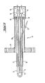
Eine bevorzugte Ausführungsform der erfindungsgemäßen Apparatur mit einem eingebauten Grenzwertgeber gemäß der Erfindung ist in der Zeichnung dargestellt. Es zeigt
- Figur 1 eine schematische Darstellung der Fließbett-Apparatur und
Figur 2 eine detaillierte Darstellung einer vorteilhaften Ausführungsform des Grenzwertgebers mit schematisierter Zuordnung zu der Fließbett-Apparatur von Figur 1.
- Figure 1 is a schematic representation of the fluid bed apparatus and
- FIG. 2 shows a detailed illustration of an advantageous embodiment of the limit value transmitter with a schematic assignment to the fluid bed apparatus from FIG. 1.
Die Fließbett-Apparatur gemäß Figur 1 besteht aus einem senkrecht stehenden zylinderförmigen Behandlungsgefäß 1. Dieses weist an seinem unteren Ende einen Fluidisierungsteil auf, der aus einem vom Zylinderquerschnitt aus nach unten verlaufenden kegelstumpfförmigen Mantel 2, einem in den Kegelstumpf eingesetzten, nach oben zulaufenden kegelförmigen Verdrängungskörper 3 und mindestens einem an der tiefsten Stelle des Fluidisierungsteils im wesentlichen tangential mündenden Einieitungsrohr 4 für das Behandlungsgas besteht. Über dem Behandlungsgefäß 1 ist ein Beruhigungsteil 5 mit einem Auslaßrohr 6 für das Abgas angeordnet. Der Beruhigungsteil 5 weist vorteilhaft einen etwas größeren Querschnitt als das Behandlungsgefäß 1 auf, um die Strömungsgeschwindigkeit des Trägergases unter die Sinkgeschwindigkeit der fluidisierten Rußteilchen abzusenken.The fluidized bed apparatus according to FIG. 1 consists of a vertically standing cylindrical treatment vessel 1. This has a fluidization part at its lower end, which consists of a truncated cone-shaped
Um diese Apparatur im Gegenstrom betreiben zu können, ist sie mit folgenden Merkmalen versehen: In den Verdrängungskörper 3 ist axial ein mit einer Schleuse 7 verbundenes Rußaustragsrohr 8 eingesetzt. Es mündet im verjüngten Ende des Verdrängungskörpers 3. Am Kopf des Beruhigungsteils 5 mündet eine mit einer Dosierschleuse 9 verbundene Rußzufuhr 10. Die Schleuse 9 wird von einem darüber angeordneten Bunker aus mit Ruß beschickt. Im Falle der Beschickung aus einem tiefer liegenden Rußbunker wird der Ruß mittels der Schleuse 9 in eine pneumatische Fördereinrichtung eindosiert und in einer mit der Rußzufuhr 10 verbundenen Abscheidevorrichtung, z. B. einem Zyklon, aus dem Förderstrom abgetrennt und in den Kopfteil 5 der Apparatur eingespeist.In order to be able to operate this apparatus in countercurrent, it is provided with the following features: In the
Um das Fließbett auf einem konstanten Niveau halten zu können, ist am Übergang zwischen Behandlungsgefäß 1 und Beruhigungsteil 5 ein optisch-elektrischer Fühler 11 angebracht, welcher die optische Dichte an der Meßstelle in elektrische Spannung umsetzt.In order to be able to keep the fluidized bed at a constant level, an optical-
Dieser als Grenzwertgeber geschaltete Fühler 11 steuert die Dosierschleuse 9.This
Prinzipiell sind für den erfindungsgemäß in der Apparatur zu verwendenden Grenzwertgeber verschiedene Ausführungen im Rahmen des beanspruchten Prinzips möglich. Eine besonders vorteilhafte und betriebssichere Ausführungsform des Grenzwertgebers besteht gemäß Fig. 2 aus einem haamadelförmigen Lichtleiter 12, der an einem Schenkel eine als Meßstrecke dienende Unterbrechung 13 aufweist. Die beiden Schenkel des unterbrochenen Lichtleiters enden in einem aus zwei lichtdichten Kammem bestehenden Meßkopf 14. Eine der Kammern enthält eine Lichtquelle 15, von der das eine Schenkelende des Lichtleiters 12 mit Licht beaufschlagt wird. In der anderen Kammer befindet sich ein Lichtempfänger 16, der mit dem zweiten Schenkelende des Lichtleiters in Verbindung steht. Als Lichtempfänger können z. B. Fotowiderstände, Fototransistoren oder Fotozellen verwendet werden. Zweckmä-Bigerweise ist auch ein Meßverstärker zur Verstärkung des lichtabhängigen elektrischen Signals des Lichtempfängers in dem Meßkopf untergebracht.In principle, various designs are possible for the limit value transmitter to be used in the apparatus according to the invention within the scope of the principle claimed. According to FIG. 2, a particularly advantageous and reliable embodiment of the limit transmitter consists of a hairpin-shaped
Die beiden Schenkel des Lichtleiters 12 befinden sich in Führungsrohren 17 und 18. Durch Dichtungen 19 werden die Lichtleiterschenkel arretiert und die Führungsrohre gasdicht abgeschlossen. Der Lichtleiter 12 und die Führungsrohre 17 und 18 sind von einem gemeinsamen Schutzrohr 20 umgeben, das mit einem Flansch 21 oder einer ähnlichen Einrichtung versehen ist, mit deren Hilfe die Meßsonde in der Weise gasdicht an der Behälterwand befestigt wird, daß die Meßstrecke 13 im Innem des Behälters zu liegen kommt, der Meßkopf 14 sich aber außerhalb des Behälters befindet. Um zu vermeiden, daß sich auf den die Meßstrecke begrenzenden Lichfleiterenden Staub ablagert, ist deren Oberfläche z. B. durch polieren oder Glattschmelzen besonders glatt ausgebildet.The two legs of the
Zusätzlich kann zur Vermeidung von Staubablagerungen in der Meßstrecke der Grenzwertgeber eine Spülleitung 22 enthalten, die an ihrem Ende mindestens eine auf die Meßstrecke 13 gerichtete Austrittsöffnung 23 besitzt, mit deren Hilfe die Meßstrecke periodisch mit Spülgasimpulsen beaufschlagt werden kann.In addition, in order to avoid dust deposits in the measuring section, the limit value transmitter can contain a
Das Verfahren zur Behandlung von fluidisiertem Ruß im Gegenstrom mit Gasen kann in der Weise durchgeführt werden, daß man aus dem Fließbett den behandelten Ruß in zeitlich konstantem Massenstrom austrägt und den Ausgangsruß in einer solchen Menge einspeist, daß das Niveau des Fließbetts konstant gehalten wird.The process for treating fluidized soot in countercurrent with gases can be carried out in such a way that the treated soot is discharged from the fluidized bed in a time-constant mass flow and the starting soot is fed in in such an amount that the level of the fluidized bed is kept constant.
In der in Fig. 1 dargestellten Apparatur geschieht das in der Weise, daß die mit dem Austragsrohr 8 verbundene Schleuse 7 mit konstanter Drehzahl betrieben wird. Sinkt die Oberfläche des Fließbetts unter das durch den Grenzwertgeber 11 festgelegte Niveau, schaltet der Grenzwertgeber die Eintragsschleuse 9 so lange ein, bis die Meßstrecke des Grenzwertgebers wieder in das Fließbett eintaucht. Auf diese Weise wird durch die Eintragsschleuse 9 bei zeitlich konstantem Austrag der Schleuse 7 immer so viel Ruß eingespeist, daß das Fließbett das durch den Grenzwertgeber 11 festgelegte Niveau beibehält. Nach einer zweiten Verfahrensvariante kann auch der Ausgangsruß über die Schleuse 9 in zeitlich konstantem Massenstrom in das Fließbett eingetragen werden. In diesem Fall wird der Rußaustrag mittels der Schleuse 7 durch den - Grenzwertgeber 11 so gesteuert, daß die Schleuse 7 in Gang gesetzt wird, wenn der Grenzwertgeber 11 in das Fließbett eintaucht und angehalten bzw. verlangsamt wird, wenn das Niveau des Fließbetts unter die durch den Grenzwertgeber festgelegte Höhe absinkt.In the apparatus shown in Fig. 1, this is done in such a way that the lock 7 connected to the discharge pipe 8 is operated at a constant speed. If the surface of the fluidized bed sinks below the level defined by the
Im Hinblick auf die Betriebssicherheit im Störfall und auf die Konstanz der Reaktionsführung wird die zuerst beschriebene Verfahrensvariante bevorzugt.With regard to operational safety in the event of a malfunction and the constancy of the reaction, the process variant described first is preferred.
Claims (8)
Applications Claiming Priority (2)
| Application Number | Priority Date | Filing Date | Title |
|---|---|---|---|
| DE19843423580 DE3423580A1 (en) | 1984-06-27 | 1984-06-27 | METHOD FOR TREATING FLUIDIZED SOOT WITH GASES, FLUID BED APPARATUS FOR CARRYING OUT THE METHOD AND LIMIT VALUES USED IN THE APPARATUS |
| DE3423580 | 1984-06-27 |
Publications (3)
| Publication Number | Publication Date |
|---|---|
| EP0167014A2 EP0167014A2 (en) | 1986-01-08 |
| EP0167014A3 EP0167014A3 (en) | 1987-09-09 |
| EP0167014B1 true EP0167014B1 (en) | 1990-01-24 |
Family
ID=6239210
Family Applications (1)
| Application Number | Title | Priority Date | Filing Date |
|---|---|---|---|
| EP85107048A Expired - Lifetime EP0167014B1 (en) | 1984-06-27 | 1985-06-07 | Process for treating fluidized carbon black with gases and fluidizing apparatus for carrying it out |
Country Status (4)
| Country | Link |
|---|---|
| US (2) | US4647444A (en) |
| EP (1) | EP0167014B1 (en) |
| JP (1) | JPS6119667A (en) |
| DE (1) | DE3423580A1 (en) |
Families Citing this family (17)
| Publication number | Priority date | Publication date | Assignee | Title |
|---|---|---|---|---|
| DE3721476C1 (en) * | 1987-06-30 | 1988-12-22 | Asea Brown Boveri | Process for regulating the fluidized bed height in a pyrolysis reactor and arrangement for carrying out the process |
| DE3816045A1 (en) * | 1987-09-11 | 1989-05-24 | Flowtec Ag | Optical fibre device, in particular for mass flow rate meters |
| US4940007A (en) * | 1988-08-16 | 1990-07-10 | A. Ahlstrom Corporation | Fast fluidized bed reactor |
| FI91971C (en) * | 1992-04-10 | 1994-09-12 | Borealis Holding As | Fluidized bed reactor |
| JP2518994B2 (en) * | 1992-04-22 | 1996-07-31 | 富士通株式会社 | Semiconductor device |
| US5435972A (en) * | 1992-10-22 | 1995-07-25 | The United States Of America As Represented By The United States Department Of Energy | Fluidization quality analyzer for fluidized beds |
| US6301546B1 (en) * | 1999-01-22 | 2001-10-09 | Exxon Research And Engineering Company | Process for detecting and monitoring changes in properties of fluidized bed solids by pressure difference fluctuation measurement |
| MXPA01012838A (en) * | 1999-06-16 | 2004-04-21 | Marine Biotech Inc | Fluidizing reactor and method for treatment of fluids. |
| DE10211098A1 (en) * | 2002-03-14 | 2003-10-02 | Degussa | Process for the production of post-treated carbon black |
| US20040140812A1 (en) * | 2003-01-21 | 2004-07-22 | Ademir Scallante | Arrangements containing electrical assemblies and methods of cleaning such electrical assemblies |
| EP1616914A1 (en) * | 2004-07-12 | 2006-01-18 | Matter Engineering AG | Apparatus for Producing Carbon Black |
| JP4274124B2 (en) * | 2005-01-11 | 2009-06-03 | 株式会社Ihi | Method and apparatus for measuring fluid circulation rate of circulating fluidized bed combustion apparatus |
| DE102005037336A1 (en) * | 2005-08-04 | 2007-02-08 | Degussa Ag | Carbon material |
| DE102007060307A1 (en) * | 2007-12-12 | 2009-06-18 | Evonik Degussa Gmbh | Process for the aftertreatment of carbon black |
| DE102008044116A1 (en) * | 2008-11-27 | 2010-06-02 | Evonik Degussa Gmbh | Pigment granules, process for their preparation and use |
| DE102010002244A1 (en) | 2010-02-23 | 2011-08-25 | Evonik Carbon Black GmbH, 63457 | Carbon black, process for its preparation and its use |
| GB201811076D0 (en) * | 2018-07-05 | 2018-08-22 | Sensient Colors Uk Ltd | Nanoparticle dispersions |
Family Cites Families (21)
| Publication number | Priority date | Publication date | Assignee | Title |
|---|---|---|---|---|
| US2445327A (en) * | 1944-08-02 | 1948-07-20 | Hydrocarbon Research Inc | Fluidizing process for gasifying carbonaceous solids |
| US2761769A (en) * | 1952-07-17 | 1956-09-04 | Gulf Research Development Co | Fluidized catalytic apparatus |
| US2864674A (en) * | 1954-07-12 | 1958-12-16 | Phillips Petroleum Co | Process and apparatus for recovery of powdered materials such as carbon black |
| US2953437A (en) * | 1956-12-21 | 1960-09-20 | Phillips Petroleum Co | Process for treating carbon black pellets |
| DE1196808B (en) * | 1957-05-08 | 1965-07-15 | Degussa | Process for the oxidative aftertreatment of dry soot |
| US3251337A (en) * | 1963-07-16 | 1966-05-17 | Robert E Latta | Spiral fluidized bed device and method for coating particles |
| US3318720A (en) * | 1963-10-14 | 1967-05-09 | Phillips Petroleum Co | Oxidation of carbon black |
| AT263405B (en) * | 1965-04-29 | 1968-07-25 | Hectronic Ag | Photoelectric liquid detector |
| GB1187567A (en) * | 1966-03-31 | 1970-04-08 | Gas Council | Apparatus for use in producing a Fluidised Bed |
| DE2139865B2 (en) * | 1971-08-09 | 1976-12-02 | Ulrich, Helmut, Dipl.-Chem., 8000 München | LEVEL INDICATOR OR CONDITION DETECTOR WITH A LIGHT GUIDING ROD PASSED THROUGH A PARTITION WALL |
| US4138471A (en) * | 1976-06-01 | 1979-02-06 | J. M. Huber Corporation | Process for reducing the polycyclic aromatic hydrocarbon content of carbon black |
| US4080927A (en) * | 1976-10-06 | 1978-03-28 | General Atomic Company | Fluidized bed-gas coater apparatus |
| JPS53114861U (en) * | 1977-02-19 | 1978-09-12 | ||
| GB2036326B (en) * | 1978-10-20 | 1983-08-17 | Klinger Ag | Liquid level sensor |
| JPS5588452U (en) * | 1978-12-15 | 1980-06-18 | ||
| DE3118907A1 (en) * | 1981-05-13 | 1982-12-02 | Degussa Ag, 6000 Frankfurt | METHOD FOR REMOVING EXTRACTABLE COMPONENTS FROM RUSSIA |
| US4423006A (en) * | 1981-05-20 | 1983-12-27 | Uop Inc. | Fluid catalyst regeneration apparatus |
| US4468567A (en) * | 1981-05-21 | 1984-08-28 | Showa Electric Wire & Cable Co., Ltd. | Liquid level detecting device and method for producing the same |
| IT1150650B (en) * | 1982-03-10 | 1986-12-17 | Montedison Spa | FLUID BED REACTOR |
| US4421523A (en) * | 1982-05-11 | 1983-12-20 | The United States Of America As Represented By The Department Of Energy | Control of bed height in a fluidized bed gasification system |
| US4453950A (en) * | 1982-09-20 | 1984-06-12 | The United States Of America As Represented By The United States Department Of Energy | Coal gasification system with a modulated on/off control system |
-
1984
- 1984-06-27 DE DE19843423580 patent/DE3423580A1/en active Granted
-
1985
- 1985-06-07 EP EP85107048A patent/EP0167014B1/en not_active Expired - Lifetime
- 1985-06-21 US US06/747,609 patent/US4647444A/en not_active Expired - Fee Related
- 1985-06-26 JP JP60138087A patent/JPS6119667A/en active Granted
-
1986
- 1986-01-14 US US06/818,590 patent/US4755358A/en not_active Expired - Fee Related
Also Published As
| Publication number | Publication date |
|---|---|
| DE3423580C2 (en) | 1988-09-29 |
| JPS6119667A (en) | 1986-01-28 |
| US4647444A (en) | 1987-03-03 |
| US4755358A (en) | 1988-07-05 |
| JPH0125514B2 (en) | 1989-05-18 |
| EP0167014A2 (en) | 1986-01-08 |
| DE3423580A1 (en) | 1986-01-02 |
| EP0167014A3 (en) | 1987-09-09 |
Similar Documents
| Publication | Publication Date | Title |
|---|---|---|
| EP0167014B1 (en) | Process for treating fluidized carbon black with gases and fluidizing apparatus for carrying it out | |
| DE533037C (en) | Process for the cycle coupling of two reactions between a solid powdery to small piece and a gaseous substance or mixture of substances | |
| DE3152314C2 (en) | ||
| DE2227176A1 (en) | Process for purifying gases containing mercury | |
| DE2116481A1 (en) | Method and device for irradiating liquids | |
| DE2159847B2 (en) | Process for the treatment of molten aluminum | |
| DE3139078C2 (en) | ||
| DE2506394A1 (en) | FLUID BED REACTOR FOR THERMAL REGENERATION OF LOADED ACTIVATED CARBONS | |
| DE2405669A1 (en) | DEVICE FOR CLEANING EXHAUST GAS OR EXHAUST AIR | |
| DE3909288C2 (en) | Process for melting glass of liquid radioactive waste | |
| DE2436792A1 (en) | METHOD OF CLEANING WASTE WATER USING ACTIVATED CARBON | |
| CH690790A5 (en) | A process for the thermal treatment of waste material. | |
| DE7817177U1 (en) | DEVICE FOR REGENERATING ACTIVE CARBON | |
| DE2749399C2 (en) | Device for the thermal regeneration of loaded adsorbents | |
| EP0740110B1 (en) | Method and apparatus for the treatment of solid combustion residues from an incinerator | |
| DE1908747A1 (en) | Process for separating pyrogenic titanium dioxide pigment from a gas suspension | |
| DE972373C (en) | Separation device for the recovery of solid suspended particles from gas or steam with a dust chamber and a downstream cyclone with flushing discharge | |
| DE2901529C2 (en) | Method and device for the continuous removal of undesired constituents from solid particles with a solvent in countercurrent | |
| EP0147617B1 (en) | Apparatus and process for the thermal regeneration of dry, pulverulent, charged carbon-containing adsorbents | |
| DE69909122T2 (en) | METHOD FOR THE HEAT TREATMENT OF FINE-PARTICLE SOLIDS, AND DEVICE FOR IMPLEMENTING IT | |
| DE2519669C3 (en) | Use of a fluidized bed reactor for the thermal regeneration of loaded adsorbents | |
| DE4234111C2 (en) | Method and device for cleaning contaminated soils | |
| EP0411412A1 (en) | Process and apparatus for regenerating active carbon loaded with heavy metals | |
| DE2854489C2 (en) | Process for removing alkyl lead compounds from gas streams | |
| DE2758400C2 (en) |
Legal Events
| Date | Code | Title | Description |
|---|---|---|---|
| PUAI | Public reference made under article 153(3) epc to a published international application that has entered the european phase |
Free format text: ORIGINAL CODE: 0009012 |
|
| 17P | Request for examination filed |
Effective date: 19850607 |
|
| AK | Designated contracting states |
Designated state(s): FR GB IT NL |
|
| EL | Fr: translation of claims filed | ||
| TCNL | Nl: translation of patent claims filed | ||
| ITCL | It: translation for ep claims filed |
Representative=s name: BARZANO' E ZANARDO ROMA S.P.A. |
|
| PUAL | Search report despatched |
Free format text: ORIGINAL CODE: 0009013 |
|
| AK | Designated contracting states |
Kind code of ref document: A3 Designated state(s): FR GB IT NL |
|
| 17Q | First examination report despatched |
Effective date: 19881025 |
|
| GRAA | (expected) grant |
Free format text: ORIGINAL CODE: 0009210 |
|
| AK | Designated contracting states |
Kind code of ref document: B1 Designated state(s): FR GB IT NL |
|
| ET | Fr: translation filed | ||
| ITF | It: translation for a ep patent filed |
Owner name: BARZANO' E ZANARDO ROMA S.P.A. |
|
| GBT | Gb: translation of ep patent filed (gb section 77(6)(a)/1977) | ||
| PLBE | No opposition filed within time limit |
Free format text: ORIGINAL CODE: 0009261 |
|
| STAA | Information on the status of an ep patent application or granted ep patent |
Free format text: STATUS: NO OPPOSITION FILED WITHIN TIME LIMIT |
|
| 26N | No opposition filed | ||
| PGFP | Annual fee paid to national office [announced via postgrant information from national office to epo] |
Ref country code: GB Payment date: 19910528 Year of fee payment: 7 |
|
| PGFP | Annual fee paid to national office [announced via postgrant information from national office to epo] |
Ref country code: FR Payment date: 19910627 Year of fee payment: 7 |
|
| ITTA | It: last paid annual fee | ||
| PGFP | Annual fee paid to national office [announced via postgrant information from national office to epo] |
Ref country code: NL Payment date: 19910630 Year of fee payment: 7 |
|
| PG25 | Lapsed in a contracting state [announced via postgrant information from national office to epo] |
Ref country code: GB Effective date: 19920607 |
|
| PG25 | Lapsed in a contracting state [announced via postgrant information from national office to epo] |
Ref country code: NL Effective date: 19930101 |
|
| GBPC | Gb: european patent ceased through non-payment of renewal fee |
Effective date: 19920607 |
|
| NLV4 | Nl: lapsed or anulled due to non-payment of the annual fee | ||
| PG25 | Lapsed in a contracting state [announced via postgrant information from national office to epo] |
Ref country code: FR Effective date: 19930226 |
|
| REG | Reference to a national code |
Ref country code: FR Ref legal event code: ST |