EP0166558A2 - Méthode et dispositif pour transporter une pièce à usiner à une station de travail - Google Patents
Méthode et dispositif pour transporter une pièce à usiner à une station de travail Download PDFInfo
- Publication number
- EP0166558A2 EP0166558A2 EP85304252A EP85304252A EP0166558A2 EP 0166558 A2 EP0166558 A2 EP 0166558A2 EP 85304252 A EP85304252 A EP 85304252A EP 85304252 A EP85304252 A EP 85304252A EP 0166558 A2 EP0166558 A2 EP 0166558A2
- Authority
- EP
- European Patent Office
- Prior art keywords
- pallet
- transport
- cart
- housing
- docking station
- Prior art date
- Legal status (The legal status is an assumption and is not a legal conclusion. Google has not performed a legal analysis and makes no representation as to the accuracy of the status listed.)
- Granted
Links
Images


Classifications
-
- B—PERFORMING OPERATIONS; TRANSPORTING
- B65—CONVEYING; PACKING; STORING; HANDLING THIN OR FILAMENTARY MATERIAL
- B65G—TRANSPORT OR STORAGE DEVICES, e.g. CONVEYORS FOR LOADING OR TIPPING, SHOP CONVEYOR SYSTEMS OR PNEUMATIC TUBE CONVEYORS
- B65G47/00—Article or material-handling devices associated with conveyors; Methods employing such devices
- B65G47/02—Devices for feeding articles or materials to conveyors
- B65G47/04—Devices for feeding articles or materials to conveyors for feeding articles
- B65G47/06—Devices for feeding articles or materials to conveyors for feeding articles from a single group of articles arranged in orderly pattern, e.g. workpieces in magazines
-
- B—PERFORMING OPERATIONS; TRANSPORTING
- B23—MACHINE TOOLS; METAL-WORKING NOT OTHERWISE PROVIDED FOR
- B23Q—DETAILS, COMPONENTS, OR ACCESSORIES FOR MACHINE TOOLS, e.g. ARRANGEMENTS FOR COPYING OR CONTROLLING; MACHINE TOOLS IN GENERAL CHARACTERISED BY THE CONSTRUCTION OF PARTICULAR DETAILS OR COMPONENTS; COMBINATIONS OR ASSOCIATIONS OF METAL-WORKING MACHINES, NOT DIRECTED TO A PARTICULAR RESULT
- B23Q7/00—Arrangements for handling work specially combined with or arranged in, or specially adapted for use in connection with, machine tools, e.g. for conveying, loading, positioning, discharging, sorting
- B23Q7/14—Arrangements for handling work specially combined with or arranged in, or specially adapted for use in connection with, machine tools, e.g. for conveying, loading, positioning, discharging, sorting co-ordinated in production lines
- B23Q7/1426—Arrangements for handling work specially combined with or arranged in, or specially adapted for use in connection with, machine tools, e.g. for conveying, loading, positioning, discharging, sorting co-ordinated in production lines with work holders not rigidly fixed to the transport devices
- B23Q7/1442—Arrangements for handling work specially combined with or arranged in, or specially adapted for use in connection with, machine tools, e.g. for conveying, loading, positioning, discharging, sorting co-ordinated in production lines with work holders not rigidly fixed to the transport devices using carts carrying work holders
Definitions
- This invention relates generally to machinery utilising interchangeable pallets providing machine tooling and/or workpieces with a common registering base.
- one aspect of the invention relates to the interchange of pallets in a system which utilises motorised parts for the automatic interchange of pallets between stations.
- FMS flexible manufacturing system
- Wire-guided carts are available from a variety of commercial suppliers, for example Eaton Corp. in the United States and AGC Division of Volvo, in Sweden.
- the carts typically have an internal elevating mechanism for raising and lowering the top deck of the cart.
- the user must affix part-specific tooling to the top deck of the cart.
- the cart may be positioned solely in response to the signal received from the wire.
- the stopping or positioning accuracy of the cart is typically within +.200 inch, or 5 millimetres. This accuracy is sufficient for grossly-positioned objects such as boxes and the like which are to be utilised in packaging systems etc.
- a common positioning means used in machine systems for positioning wire-guided carts is to equip the cart with at least one detent socket, and to have a precisely positioned detent pin positioned in the machine floor proximal the machine site.
- the detent pin is fired into the detent socket of the cart and serves to pull the cart into an aligned position. Thereafter, the precisely aligned pallet on the cart may be successfully interchanged with the machine station.
- the elevational capability of the cart is utilised to bring the pallet precisely into a vertical alignment with the machine station for the interchange. Also, it should be noted that the pallet leaves the part-specific tooling completely intact on the cart. Typically, the cart will remain at the machine site until a pallet is loaded onto the cart.
- the detent pin extending from the floor serves as a collection site for swarf, grit and other deleterious matter; the pin encounters great forces as it attempts to move the combined weight of the pallet, pallet tooling, and cart into correct alignment with the machine; and, the cart is generally tied up at the machine site during the machine working time because of the detent assembly required to locate and fix the cart.
- a palletised part-handling apparatus comprising a plurality of pallets as common bases and mbvable, guided carts for transferring said pallets from one station to another, pallet transport means on each cart for supporting and locking a pallet during transfer movements, holding means for supporting and locking said pallet transport means on said cart during transfer movements, a stationary docking station for receiving a transferred cart and pallet, means for releasing said pallet transport means from said holding means to said docking station and means for releasing said pallet from said pallet transport means at said docking station.
- the pallet transport means can be deposited at a docking station, thus leaving the cart free to effect other transfers, whilst the pollet and pallet transport means previously borne by the cart remain within the docking station and an adjacent machining station. Furthermore, the positioning of the cart relative to the docking station can be controlled with sufficient accuracy by radiofrequency signals from a wire embedded in the floor.
- pallet transport apparatus and a method of moving a workpiece into a working station as defined in the claims appended hereto.
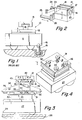
- figure I depicts a guided cart system 10 of the prior art, wherein a wheeled unmanned cart I has a top deck 12 which is movable in vertical directions, and a pallet 13 is carried on specific tooling 14 mounted to the top deck 12 of the cart 11.
- the pallet 13 is transported to a machine station (not shown).
- a tapered locating pin 15 which is mounted in the floor is powered up into a companion socket 16 in the cart II, to provide accurate horizontal positioning of the cart I I for the interchange of pallets 13 with the machine station.
- An elevating assembly within the cart I provides the vertical accuracy of position for the pallet interchange to take place.
- FIG. 2 depicts a typical pallet 13.
- the pallet 13 is a generally rectangular block of cast iron, having a series of "T"-slots 17 machined in its upper surface 18, for mounting tooling and/or workpieces.
- the bottom surface 19 of the pallet has large "T"-slot 20 machined throughout, so that a rectangular way system is created for sliding the pallet 13, and the "T"-slot facilitates pallet clamping at a machine station.
- One end 21 of the pallet 13 is fitted with a stud 22 having a stem 23 and an outboard enlarged head 24 .
- the machine station is provided with a push-pull rod 25, having a birfurcated end plate 26 which is able to trap the head of the pallet stud 22, as the pallet 13 is lowered. In such fashion, the rod 25 therefore can move the pallet 13 into, or out of, a machine station at interchange time.
- FIG. 3 illustrates the present invention, wherein a wire-guided cart 27 i.e. an unmanned wheeled vehicle guided from a signal wire 28 embedded in the floor 29, has an elevatable top deck 30, which is fitted with a unique deck plate 31.
- the deck plate 31 has a plurality of ball castors 32 secured thereto, and a pair of tapered locating pins 33 are also secured to the deck plate 31.
- the ball castors 32 support a separate pallet transport 34 comprised, in part, of a housing 35 having an enclosed box structure 36 (which is fabricated weldment), welded to a bottom plate 37.
- a plurality of stiffening ribs or gussets 38,39 are welded to the sides of the box structure 36 and the plate 37 and a pair of hardened "T"-shaped, rails 40,41 are affixed to the top side of the transport housing 35.
- a pallet locking pin 42 is shown extending upward from the transport housing 35 and engaging the pallet 13 during the time of transport. The pallet 13 is therefore locked in position on the "T"-shaped ways 40,41 until interchange time when the pallet locking pin 42 is retracted into the housing 35.
- the tapered locating pin 33 of the cart deck plate is shown engaging a movable socket i.e.
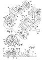
- FIG 4 shows the cart 27 of figure 3 with the pallet transport 34 removed to show the deck plate 31.
- the four ball castors 32 are shown in a squared pattern, and the two tapered locating pins 33 are secured to the deck plate 31 between the castors 32.
- the sectional view of figure 5 depicts in enlarged fashion, the locating elements of figure 4, wherein the ball castor 32 is comprised of a short cylindrical housing 47 having a pilot diameter 48 received in a locating pilot hole 49 in the deck plate 31.
- a clearance-drilled hole 50 is provided in the top 51 of the housing 47, and a plurality of rollers 52 are received on horizontal pins 53 locked in the housing 47 by set screws 54 (see figure 6).
- the three rollers 52 are equally spaced around the ball 55, and are contained from side movement by clearance slots 56 cut through the housing 47.
- the rollers 52 have a concave groove 57 to conform to the ball 55.
- the ball 55 is seated in the rollers grooves 57 and is prevented from outward movement by a cover 58 which is received on the castor housing 47 and secured by screws 59.
- the cover 58 has a cylindrical skirt 60 welded thereto which extends along the cylindrical body of the housing 47.
- the cover 58 has a clearance hole 61 drilled from its underneath side to such depth that the tapered drill point will not break through, and the resulting diameter in the top of the cover 58 will clear the exposed ball surface, yet prevent the ball 55 from escaping.
- Mounting screws 62 are provided through the castor housing 47 to secure the assembly to the deck plate 31.
- the tapered locating pin 33 has short straight pin section 63 with a conical point 64 at the top, and a flange diameter 64 is provided at the bottom for mounting against the deck plate 31.
- a plurality of screws 65 passing through the flange diameter 54 secure the locating pin 33 in position on the deck plate 31.
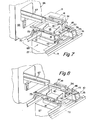
- a machine station 66 having pallet- receiving machine ways 67 extending from the machine 68.
- the machine station 66 may comprise any station with pallet- receiving ways 67, a metal cutting machine; inspection machine; a washing machine; and pallet storage mechanism, etc.
- a pallet transport docking station 69 is shown, generally comprising spaced-apart rail brackets 70,71.
- a plurality of flat, hardened, locating pads 72 are mounted to the brackets 70,71 to provide vertical locaton for the pallet transport 34, while a plurality of fixed tapered locating pins 73 are used to provide horizontal location for the transport 34.
- the cart 27 has the deck plate 31 elevated to the topmost position, i.e.
- the pallet transport 34 is shown supporting a pallet 13 (in phantom) on its "T"-shaped ways 40,41.
- a cam support bracket 74 is mounted to one decking station bracket 71, and the cam bracket 74 supports a hardened cam plate 75 which is essentially a horizontal plate having lead-in ramp surfaces 76 at each end.
- the crank. 46 shown in figure 7 is in the "normally down", spring-biased position relative to the transport housing 35.
- the crank 46 has an anti-friction cam follower 77 extending into proximity with the cam plate 75.
- the transport 34 is shown immediately after the deck plate 31 is lowered in the direction of the broad arrow, to such position where the transport 34 is vertically positioned on the hardened, flat locating pads 72 and is horizontally positioned by the tapered locating pins 73 so that the "T"-shaped transport ways 40,41 are in line with the machine ways 67 and the pallet may successfully slide into the machine station 66.
- the cam follower 77 of the crank 46 is shown in contact with the cam plate 75, and the lowering of the crank shaft 45 about the cam followed 77 (due to the weight of the pallet transport 34) causes the crank 46 to relatively move in a counterclockwise direction, overcoming the internal spring-biasing force.
- the pallet locking.pin 42 and the socket rod 44 (not shown but extending from the bottom of the pallet transport housing) are retracted.
- the docking station 69 is shown with the pallet transport removed for clarity, and the station is comprised of two independent parallel brackets 70, 71 which are fabricated from square hollow structural steel tubing.
- One bracket 70 has a single rail 78 extending along its top surface, and the other bracket has double rails 79,80 extending along its top surface.
- the single rail bracket 70 is positioned alongside the machine station 66 (see figure 7) so that the machine ways 67 may be brought as close as possible to the pallet transport 34.
- the double rail bracket 71 provides support for the cam bracket 74 which subtends the two rails 79,80.
- the cam bracket 74 is a fabrication affixed to a plate 81 welded to the two rails 79, 80 and the cam bracket 74 has a facial slot 82 formed in the side disposed toward the opposite station bracket 70.
- the slot 82 contains the two identical cam plates 75, which are fastened with screws 83 to the cam bracket 74.
- the lead-in ramp surface 76 of the cam plates 75 serves to provide a smooth entry for the cam follower 77 due to any positioning misalignments of the crank 46 (see Figures 7 and 8) with respect to the docking station 69.
- the double rail bracket 71 has a pair of hardened locating pads 72 spaced apart along its inside rail 79, and the pads 72 are fastened to a plate 84 which is welded to the inside rail 79.
- the locating pad 72 has a small hole 85 drilled in its top surface, and a horizontal hole 86 is drilled and pipe-tapped in one side of to interconnect with the vertical hole 85. All locating pods 72 are connected to an air pressure line 87 which in turn, has a pressure switch 88 to sense when the air flow from an air source 89 is closed off, therefore, signalling when a pallet transport 34 is "fully down” and positively located on the pads 72.
- a proximity switch 90 is threadably received through the rail plate 9 supporting the rear locating pad 72 of the inside rail 79. The proximity switch 90 is adjustably held in position by a locknut 92, and serves to indicate the presence of a pallet transport 34.
- the single rail bracket 70 likewise supports corresponding locating pads 72, and the front pad plate 93 has a proximity switch 90 threadably received therethrough and secured with a locknut 92 in a similar fashion to that of the double rail bracket 71.
- a pair of hardened tapered locating pins 73 having rectangular bases extend vertically from the rail plates 93, 94 of the single rail bracket 70.
- the conical locating pins 73 serve to provide horizontal positioning for the pallet transport 34. Flow of air through the holes 85 cleans the mutually facing surfaces of the locating pads as these approach one another.
- Use of the pressure switch 88 to provide a "fully down" signal is optional.
- the proximity switches 90 are. alternatives to the pressure switch 88 but may be used in addition thereto.
- the docking station brackets 70, 71 have side-extending shelves 95 welded to the bottom, and each shelf 95 contains a pair of levelling screws 96 which are used to adjust the vertical position of the brackets 70, 71.
- a central screw 97 passing through the hollow levelling screw 96 serves to lag the assembly down tight to the floor in a conventional manner.
- the double rail bracket 71 need only be positioned accurately in a vertical direction, but the single rail bracket 70 must be positioned in a horizontal direction as well since it carries the conical locating pins 73 which positively locate the transport 34 with respect to a machine station 66.
- a pair of"U"- shaped brackets 98 are provided on the floor adjacent the single rail bracket 70 and horizontal screws 99 received through the "U"-shaped bracket 98 react against a welded tang 100 extending from each shelf 95 of the single-rail bracket 70 to provide horizontal adjustment.
- Figure 10 depicts an end view of the docking station 69, showing the pallet transport 34 supported in the "fully down” position on the single rail and double rail brackets 70, 71.
- the bottom plate 37 of the transport housing 34 has a plurality of welded plates 101,102 which, in turn, carry hardened locating pads 103 to mate with the locating pads 72 of the brackets 70,71.
- the cart 27 is shown in plantom, with its deck plate 31 lowered so that the ball castors 32 no longer contact the transport housing 35.
- the transport housing 35 contains a hardened, flanged bushing 104 which has a central bore 105 adapted to fit closely with the tapered locating pin 73 of the single rail bracket 70.
- a lead-in-taper 106 is machined in the bushing 104 at the same angle as the conical point of the pin 73 so that misalignment of the transport 34 may be accomodated and overcome as the transport 34 is manoeuvred into position by the lowering deck plate 31.
- the pallet 13 is pulled by the machine push/pull rod 25 onto the machine ways 67 at one end of the transport i.e. the end nearest the single rail bracket 70 of the docking station 69.
- the crankshaft 45 extends from the other end of the transport housing 35, and the antifriction cam follower 77, mounted to a crank pin 107, is shown in contact with the lower cam plate 75.
- the cam plates 75 are carried by the cam bracket 74 which is fixed by screws 108 to the support plate 81 of the double rail bracket 71.
- the phantom positions of the cam follower 77 depict that initial endwise positioning inaccuracies may be accommodated but, as the transport 34 is lowered onto the tapered locating pins 73, the transport 34 will be pulled into proper alignment.
- Figure I I is an end view of the crank 46, showing (in solid) the "fully down” position, wherein the crank 46 is rotated in a counterclockwise direction to a position approximately 30° above the horizontal line.
- the phantom position of the crank 46 depicts the pallet transport 34 in the "fully raised” position wherein the internal spring-biasing force (which will be discussed in connection with figure 15) restores the crank 46 to its fully clockwise position.
- the space between the upper and lower cam plates 75 provides clearance around the cam follower 77, so that during the initial portion of a lowering motion, the crank 46 will not be moved.
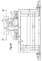
- the section shown in figure 12 is taken through the crankshaft 45, shown mounted in front and rear bearings 109, 110 which in turn, are supported in front and rear bearing caps 111,112 affixed to the box structure 36 of the transport housing 35.
- the forward end of the crankshaft 45 extends from the housing 35 and supports a gear 113 within the housing 35.
- a woodruff key 114 serves to connect the gear 113 to the shaft 45.
- the gear 113 is located on a reduced diameter 115 of the crankshaft 45 and is shouldered against the large main diameter of the shaft 45.
- a spacer sleeve 117 is provided on the crankshaft 45 between the gear 113 and the bearing 109 so that the gear 113 will not move axially.
- the bearing 109 is retained in the front bearing cap III by a front retaining ring 118 received in the bearing cap I I and loaded against the inner race of the bearing 109.
- the outer race of the bearing 109 is shouldered against the end 119 of the bearing bore 120.
- the crank 46 has a straight arm portion 121 and a hub 122 is welded to the arm 46a.
- a bore 123 is provided through the hub 122 and arm 121.
- the crankshaft 45 has a pair of side flats 125 machined to provide a thin width which will fit closely in the slot 124 of the arm 121 to create a torque couple between the two, as shown in figure 13.
- a threaded end 126 is provided on the crankshaft 45 and a washer 127 and castellated locknut 128 are provided thereon.
- a cotter pin 129 is received through the shaft 45 to prevent the nut 128 from backing off.
- the outboard end of the crank 121 arm has a hole 130 parallel to the crankshaft 45, and a crank pin 107 is mounted in the hole 130.
- the crank pin 107 has a pilot diameter 131 received through the hole 130 and a washer 127 and castellated locknut 128 are held by a threaded end 132 of the crank pin 107.
- a cotter pin 129 is received through the crank pin 107.
- the crank pin 107 has a large main diameter 133 extending from the outer face of the crank arm 121, and the crank pin 107 is reduced at a tapered section 134 to a small shoulder diameter 135, extending to a smaller bearing diameter 136.
- the bearing diameter 136 supports the antifriction cam follower 77 which is entrapped against the shoulder diameter 135 by a washer 127, and locknut 128, and cotter pin 129, received on the threaded outboard end 137 of the crank pin 107.
- the crankshaft gear 113 is enmeshed with a vertical rack portion 138 of the movable socket rod 44.
- the socket rod 44 is prevented from rotating by means of a headed pin 139 received in the side of the transport housing 35 and having a keying nose 140 engaged in a key slot 141 of the socket rod 44.
- a guide sleeve 142 is received around the socket rod 44 and prevented from rotating by a pilot diameter 143 of the pin 139 received in a hole 144 through the side of the guide sleeve 142.
- the gear 113 extends through a clearance slot 145 in the sleeve 142.
- the rear end of the crankshaft 45 is reduced from the main diameter 116, and the reduced diameter 146 extends through: a short lever 147; a spacer ring 148; and a drive gear 113.
- the lever 147 and gear 113 are connected through woodruff keys 114 to the shaft 45.
- the gear mesh 113 is in mesh with a rack portion 138 of the second socket rod 44 as previously described.
- a spacer ring 149 is received on the shaft 45 between the gear 113 and the end bearing 110, and the assembly is locked together by an end plate 150 held to the inner race of the bearing 110 by a screw 151 received in the end of the crankshaft 45.
- the bearing 110 is constrained against axial movement in the rear bearing cap 112 by a shoulder 152 at the inboard end of the bearing bore 153, and a retaining ring 154 provided on the bearing cap 112.
- a clearance bore 155 provided in the bearing cap 112 extends around the retaining plate 150 of the crankshaft 45.
- the crank lever 147 is engaged with a slot 156 in the side of the pallet locking pin 42 to provide vertical movement of the locking pin 42 through its guide bushing 157.
- FIG. 14 The elevational view of figure 14 is shown looking at the transport 34 from the side of the double rail bracket 71.
- the view is depicted with the transport 34 in the "fully down” position, i.e. with the crank.46 rotated in a counterclockwise direction and having a pallet 13 ready for interchange on the transport ways 40,41.
- the hardened locating pads 103 of the transport 34 are shown in contact with the locating pads 72 of the brackets 70,71.
- Figure 15 is a plan view of the pallet transport 34.
- the crank 46 and crank pin 107 are seen extending from one side of the transport housing 35.
- the pallet locking pin 42 is shown between the pallet support ways 40,41.
- the transport housing 35 contains the pair of socket rod assemblies 158 which will be more fully depicted in the sectional view of figure 16.
- Four hardened circular locating pads 159 are provided on the pallet transport 34 to prevent wear at the ball castor sites.
- the four flat locating pads 103 are shown affixed to the bottom surface of the transport 34 to provide for vertical positioning while the two pin bushings 104 are shown affixed to one side of the pallet transport 34 for the horizontal positioning of the unit.
- One side of the transport housing has a central relief 160, to provide clearance for machine ways 67 which may extend into dose proximity with the pallet support ways 40, 41 of the transport 34.
- FIG 16 is an elevational section through the crankshaft 45 and the socket rod assemblies 158.
- the socket rod 44 is shown having its rack portion 138 in mesh with the crankshaft gear 113.
- the socket rod 44 slides in the guide sleeve 142 which extends through bores 161,162 in the top and bottom walls of the housing 35.
- the top of the guide sleeve 142 has a flange 163, and screws 164 pass through a cover plate 165 and the flange 163 to secure the assembly 158 to the transport housing 35.
- a grease fitting 166 is provided in the side of the cover plate 165 with suitable interdrilling to introduce grease into the assembly 158.
- the socket rod 44 is provided with a blind clearance hole 167 drilled to approximately one-fourth of the overall length.
- a guide pin 168 affixed in the cover plate 165 extends into the clearance hole 167 approximately to full depth when the socket rod 44 is in the fully retracted position (shown).
- a preloaded spring 169 is received in the clearance hole 167, reacting against the rod 44 and cover plate 165, to normally bias the socket rod 44 downward, thus rotating the crankshaft 45 in a clockwise direction.
- the guide pin 168 serves to keep the spring 169 from buckling.
- Figure 16 further shows the pallet locking pin 42 in the fully retracted position.
- the locking pin 42 is guided in a bushing 157 located in a cylindrical bore 170 in the housing 35.
- the pallet guide ways 40,41 are secured to the transport housing 35 by a plurality of cap screws 171.
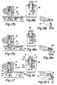
- FIGS 17,18 and 19 should be viewed simultaneously, since they are related in time and space.
- the bottom plate 37 of the transport housing 35 is common to all views and is shown therefor by a phantom line connecting the views for ease of understanding.
- the location of all elements occurs with the deck plate 31 of the cart 27 in the "fully down" position i.e. with the baU castor 32 and tapered locating pin 33 away from the pallet transport 34.
- the pallet transport 34 is seated on the locating pads 72 and having its bushing 104 (see figure 19) journalled on the tapered locating pin 73 of the single rail bracket 70.
- the socket rod 44 is shown in the retracted position, i.e. within the transport housing 35.
- the socket rod 44 has a precision socket bore 172 closely-machined to fit the locating pin 33 of the deck plate 31.
- a lead-in-taper 173 is provided at the bottom of the socket rod 44 so that horizontal misalignment may be accommodated between the transport 34 and the locating pin 33 when the cart 27 picks up the transport 34.
- the phantom positions of the pin 33 serve to show the degrees of horizontal misalignment which may be accommodated.
- Figure 18 shows the pallet locking pin 42 in the fully retracted position from the pallet 13 and pallet bore 174.
- the lever 147 of the crankshaft is shown rotated in the furthermost counterclockwise direction, thus retracting the locking pin 42.
- the locking pin 42 has a side slot 156 for receiving the crankshaft lever 147.
- a hardened replaceable nose cap 175 is received on the top of the locking pin 42.
- the nose cap 175 has a slight taper.
- the pallet locking pin 42 is journalled in a flanged guide bushing 157 secured to the transport housing 35.
- the flanged bushing 157 has a seal 176 at its top end and a grease fitting 177 provided in the flange 178 of the bushing 157 serves to introduce lubricant to assist the pin 42 in sliding.
- the locking pin 42 has a small diameter straight pin 179 extending radially into a guide slot 180 in the guide bushing 157 to prevent the locking pin 42 from rotating.
- the deck plate 31 is raised to a position where the ball castor 32 contacts the locating pad 159 of the transport 34 and begins the initial lift.
- the lifting of the transport 34 enables the crank 46 (figure 11) to rotate in a clockwise direction under the influence of the socket rod biasing spring 169.
- the socket rod 44 therefor begins its descent from the bottom plate 37 of the transport housing 35 as the locating bushing 104 of the transport 34 is leaving the locating pin 73 in figure 19a.
- the crank lever 147 lifts the pallet locking pin 42 into engagement with the pallet bore 174.
Landscapes
- Engineering & Computer Science (AREA)
- Mechanical Engineering (AREA)
- Feeding Of Workpieces (AREA)
- Automobile Manufacture Line, Endless Track Vehicle, Trailer (AREA)
- Automatic Assembly (AREA)
- Grinding Of Cylindrical And Plane Surfaces (AREA)
- Multi-Process Working Machines And Systems (AREA)
- Intermediate Stations On Conveyors (AREA)
- Pallets (AREA)
Priority Applications (1)
| Application Number | Priority Date | Filing Date | Title |
|---|---|---|---|
| AT85304252T ATE45907T1 (de) | 1984-06-14 | 1985-06-14 | Verfahren und vorrichtung zum transport eines werkstueckes in eine bearbeitungsstation. |
Applications Claiming Priority (2)
| Application Number | Priority Date | Filing Date | Title |
|---|---|---|---|
| GB8415194 | 1984-06-14 | ||
| GB848415194A GB8415194D0 (en) | 1984-06-14 | 1984-06-14 | Pallet transport |
Publications (3)
| Publication Number | Publication Date |
|---|---|
| EP0166558A2 true EP0166558A2 (fr) | 1986-01-02 |
| EP0166558A3 EP0166558A3 (en) | 1986-10-08 |
| EP0166558B1 EP0166558B1 (fr) | 1989-08-30 |
Family
ID=10562429
Family Applications (1)
| Application Number | Title | Priority Date | Filing Date |
|---|---|---|---|
| EP85304252A Expired EP0166558B1 (fr) | 1984-06-14 | 1985-06-14 | Méthode et dispositif pour transporter une pièce à usiner à une station de travail |
Country Status (4)
| Country | Link |
|---|---|
| EP (1) | EP0166558B1 (fr) |
| AT (1) | ATE45907T1 (fr) |
| DE (1) | DE3572617D1 (fr) |
| GB (2) | GB8415194D0 (fr) |
Cited By (7)
| Publication number | Priority date | Publication date | Assignee | Title |
|---|---|---|---|---|
| US4861220A (en) * | 1988-05-27 | 1989-08-29 | Caterpillar Industrial Inc. | Load positioning assembly and method |
| DE8908895U1 (fr) * | 1989-07-21 | 1989-09-21 | Burkhardt + Weber Gmbh, 7410 Reutlingen, De | |
| EP1197422A3 (fr) * | 2000-10-18 | 2002-10-02 | VA TECH Transport- und Montagesysteme GmbH & Co | Dispositif et procédé de positionnement pour chariots de transport dans des postes de travail |
| US8046895B2 (en) | 2008-01-21 | 2011-11-01 | Ford Motor Company | System and method for assembling a vehicle body structure |
| CN108526980A (zh) * | 2018-06-13 | 2018-09-14 | 上海交大智邦科技有限公司 | 可移动式工件夹具交换装置 |
| CN108655804A (zh) * | 2018-06-13 | 2018-10-16 | 上海交大智邦科技有限公司 | 一种全自动快速切换工装夹具系统 |
| CN109807676A (zh) * | 2019-02-12 | 2019-05-28 | 东华大学 | 一种自动化工件搬运载板系统 |
Families Citing this family (6)
| Publication number | Priority date | Publication date | Assignee | Title |
|---|---|---|---|---|
| US4915569A (en) * | 1987-02-05 | 1990-04-10 | Oerlikon Motch Corporation | Combination machine tool apparatus and pallet changing system |
| DE4330686A1 (de) * | 1993-09-10 | 1995-03-16 | Nagel Masch Werkzeug | Verfahren und Vorrichtung zum Transportieren von Werkstücken |
| US6918577B2 (en) | 2002-09-24 | 2005-07-19 | Ford Motor Company | Tooling plate for a flexible manufacturing system |
| US7178227B2 (en) | 2002-09-24 | 2007-02-20 | Ford Motor Company | Workpiece presenter for a flexible manufacturing system |
| US6899377B2 (en) | 2002-09-24 | 2005-05-31 | Ford Motor Company | Vehicle body |
| CN110421531A (zh) * | 2019-08-15 | 2019-11-08 | 奇瑞汽车股份有限公司 | 一种发动机与变速箱的合装方法及所采用的工装 |
Citations (2)
| Publication number | Priority date | Publication date | Assignee | Title |
|---|---|---|---|---|
| DE3101659A1 (de) * | 1981-01-20 | 1982-08-26 | Friedrich Kessler, Werkzeug- und Maschinenbau, 8032 Gräfelfing | Vorrichtung zum zu- und wegfuehren und werkstuecktraegern bei montage- und bearbeitungsstationen |
| DE3316050A1 (de) * | 1983-05-03 | 1984-11-08 | Friedrich Deckel AG, 8000 München | Einrichtung zum transport von werkstueckpaletten |
Family Cites Families (1)
| Publication number | Priority date | Publication date | Assignee | Title |
|---|---|---|---|---|
| DE3115775A1 (de) * | 1981-04-18 | 1982-11-11 | Ernst Wagner Kg, 7410 Reutlingen | "vorrichtung zum uebernehmen, ausrichten und uebergeben einer palette o.dgl." |
-
1984
- 1984-06-14 GB GB848415194A patent/GB8415194D0/en active Pending
-
1985
- 1985-06-14 DE DE8585304252T patent/DE3572617D1/de not_active Expired
- 1985-06-14 AT AT85304252T patent/ATE45907T1/de not_active IP Right Cessation
- 1985-06-14 GB GB08515143A patent/GB2162450B/en not_active Expired
- 1985-06-14 EP EP85304252A patent/EP0166558B1/fr not_active Expired
Patent Citations (2)
| Publication number | Priority date | Publication date | Assignee | Title |
|---|---|---|---|---|
| DE3101659A1 (de) * | 1981-01-20 | 1982-08-26 | Friedrich Kessler, Werkzeug- und Maschinenbau, 8032 Gräfelfing | Vorrichtung zum zu- und wegfuehren und werkstuecktraegern bei montage- und bearbeitungsstationen |
| DE3316050A1 (de) * | 1983-05-03 | 1984-11-08 | Friedrich Deckel AG, 8000 München | Einrichtung zum transport von werkstueckpaletten |
Non-Patent Citations (1)
| Title |
|---|
| WERKSTATTSTECHNIK, ZEITSCHRIFT F]R INDUSTRIELLE FERTIGUNG, vol. 73, no. 5, May 1983, pages 291-296, Springer Verlag, Berlin, DE; S. INABA: "Automatisierung in Fertigung und Montage in Unternehmen des elektronischen Ger{tebaus" * |
Cited By (8)
| Publication number | Priority date | Publication date | Assignee | Title |
|---|---|---|---|---|
| US4861220A (en) * | 1988-05-27 | 1989-08-29 | Caterpillar Industrial Inc. | Load positioning assembly and method |
| EP0343804A1 (fr) * | 1988-05-27 | 1989-11-29 | Caterpillar Industrial Inc. | Montage et méthode de positionnement de charge |
| DE8908895U1 (fr) * | 1989-07-21 | 1989-09-21 | Burkhardt + Weber Gmbh, 7410 Reutlingen, De | |
| EP1197422A3 (fr) * | 2000-10-18 | 2002-10-02 | VA TECH Transport- und Montagesysteme GmbH & Co | Dispositif et procédé de positionnement pour chariots de transport dans des postes de travail |
| US8046895B2 (en) | 2008-01-21 | 2011-11-01 | Ford Motor Company | System and method for assembling a vehicle body structure |
| CN108526980A (zh) * | 2018-06-13 | 2018-09-14 | 上海交大智邦科技有限公司 | 可移动式工件夹具交换装置 |
| CN108655804A (zh) * | 2018-06-13 | 2018-10-16 | 上海交大智邦科技有限公司 | 一种全自动快速切换工装夹具系统 |
| CN109807676A (zh) * | 2019-02-12 | 2019-05-28 | 东华大学 | 一种自动化工件搬运载板系统 |
Also Published As
| Publication number | Publication date |
|---|---|
| GB2162450B (en) | 1988-08-17 |
| EP0166558A3 (en) | 1986-10-08 |
| GB2162450A (en) | 1986-02-05 |
| GB8515143D0 (en) | 1985-07-17 |
| DE3572617D1 (en) | 1989-10-05 |
| GB8415194D0 (en) | 1984-07-18 |
| ATE45907T1 (de) | 1989-09-15 |
| EP0166558B1 (fr) | 1989-08-30 |
Similar Documents
| Publication | Publication Date | Title |
|---|---|---|
| EP0166558B1 (fr) | Méthode et dispositif pour transporter une pièce à usiner à une station de travail | |
| EP0340232B1 (fr) | Agencement et procede de transfert de pallettes | |
| US4354796A (en) | Air float power translation system | |
| US4356904A (en) | Machine tool | |
| US4538950A (en) | Automatic system for conveying works in a machine shop | |
| US4626160A (en) | Unmanned transfer system for transferring works to machining tools | |
| EP0037135B1 (fr) | Système de transfert de palettes | |
| US4861220A (en) | Load positioning assembly and method | |
| US4746258A (en) | Floating table for article transport vehicle | |
| US4485911A (en) | Transfer machine | |
| US4599786A (en) | Grinding machine with apparatus for changing grinding wheel tools and workpieces | |
| US5860900A (en) | End effector storage station | |
| US6257108B1 (en) | Work transfer method and apparatus in machine tool with movable spindle and machining system | |
| US3540566A (en) | Connector system | |
| US5344276A (en) | Stationary positioning device for a handling trolley having extendable centering finger assembly | |
| US5316100A (en) | Stationary direction changing device for a handling trolley | |
| EP0254043B1 (fr) | Appareil et procédé pour usiner des pièces | |
| US5810541A (en) | Apparatus and method for manually exchanging pallets | |
| CN212216877U (zh) | 一种基于柔性联结和气动吸附的冲压自动上料装置 | |
| GB2189416A (en) | Pallet transfer apparatus | |
| US4326831A (en) | Apparatus for transferring a workpiece in an air float system | |
| CN116873439A (zh) | 物流系统 | |
| US5970599A (en) | Milling machine | |
| JPS6247656B2 (fr) | ||
| US4359309A (en) | Method for transferring a workpiece in an air float system |
Legal Events
| Date | Code | Title | Description |
|---|---|---|---|
| PUAI | Public reference made under article 153(3) epc to a published international application that has entered the european phase |
Free format text: ORIGINAL CODE: 0009012 |
|
| AK | Designated contracting states |
Designated state(s): AT BE CH DE FR GB IT LI LU NL SE |
|
| PUAL | Search report despatched |
Free format text: ORIGINAL CODE: 0009013 |
|
| AK | Designated contracting states |
Kind code of ref document: A3 Designated state(s): AT BE CH DE FR GB IT LI LU NL SE |
|
| 17P | Request for examination filed |
Effective date: 19870313 |
|
| 17Q | First examination report despatched |
Effective date: 19880510 |
|
| GRAA | (expected) grant |
Free format text: ORIGINAL CODE: 0009210 |
|
| AK | Designated contracting states |
Kind code of ref document: B1 Designated state(s): AT BE CH DE FR IT LI LU NL SE |
|
| REF | Corresponds to: |
Ref document number: 45907 Country of ref document: AT Date of ref document: 19890915 Kind code of ref document: T |
|
| ITF | It: translation for a ep patent filed |
Owner name: JACOBACCI & PERANI S.P.A. |
|
| REF | Corresponds to: |
Ref document number: 3572617 Country of ref document: DE Date of ref document: 19891005 |
|
| ET | Fr: translation filed | ||
| PLBI | Opposition filed |
Free format text: ORIGINAL CODE: 0009260 |
|
| 26 | Opposition filed |
Opponent name: MERCEDES- BENZ AG Effective date: 19900530 |
|
| NLR1 | Nl: opposition has been filed with the epo |
Opponent name: MERCEDES- BENZ AG. |
|
| ITTA | It: last paid annual fee | ||
| PLBN | Opposition rejected |
Free format text: ORIGINAL CODE: 0009273 |
|
| STAA | Information on the status of an ep patent application or granted ep patent |
Free format text: STATUS: OPPOSITION REJECTED |
|
| 27O | Opposition rejected |
Effective date: 19910404 |
|
| NLR2 | Nl: decision of opposition | ||
| PGFP | Annual fee paid to national office [announced via postgrant information from national office to epo] |
Ref country code: FR Payment date: 19940609 Year of fee payment: 10 |
|
| PGFP | Annual fee paid to national office [announced via postgrant information from national office to epo] |
Ref country code: AT Payment date: 19940614 Year of fee payment: 10 |
|
| PGFP | Annual fee paid to national office [announced via postgrant information from national office to epo] |
Ref country code: SE Payment date: 19940615 Year of fee payment: 10 |
|
| PGFP | Annual fee paid to national office [announced via postgrant information from national office to epo] |
Ref country code: NL Payment date: 19940630 Year of fee payment: 10 |
|
| EPTA | Lu: last paid annual fee | ||
| EAL | Se: european patent in force in sweden |
Ref document number: 85304252.1 |
|
| PGFP | Annual fee paid to national office [announced via postgrant information from national office to epo] |
Ref country code: DE Payment date: 19950607 Year of fee payment: 11 |
|
| PG25 | Lapsed in a contracting state [announced via postgrant information from national office to epo] |
Ref country code: AT Effective date: 19950614 |
|
| PGFP | Annual fee paid to national office [announced via postgrant information from national office to epo] |
Ref country code: CH Payment date: 19950614 Year of fee payment: 11 |
|
| PG25 | Lapsed in a contracting state [announced via postgrant information from national office to epo] |
Ref country code: SE Effective date: 19950615 |
|
| PGFP | Annual fee paid to national office [announced via postgrant information from national office to epo] |
Ref country code: LU Payment date: 19950701 Year of fee payment: 11 |
|
| PGFP | Annual fee paid to national office [announced via postgrant information from national office to epo] |
Ref country code: BE Payment date: 19950809 Year of fee payment: 11 |
|
| PG25 | Lapsed in a contracting state [announced via postgrant information from national office to epo] |
Ref country code: NL Effective date: 19960101 |
|
| PG25 | Lapsed in a contracting state [announced via postgrant information from national office to epo] |
Ref country code: FR Effective date: 19960229 |
|
| NLV4 | Nl: lapsed or anulled due to non-payment of the annual fee |
Effective date: 19960101 |
|
| EUG | Se: european patent has lapsed |
Ref document number: 85304252.1 |
|
| REG | Reference to a national code |
Ref country code: FR Ref legal event code: ST |
|
| PG25 | Lapsed in a contracting state [announced via postgrant information from national office to epo] |
Ref country code: LU Free format text: LAPSE BECAUSE OF NON-PAYMENT OF DUE FEES Effective date: 19960614 |
|
| PG25 | Lapsed in a contracting state [announced via postgrant information from national office to epo] |
Ref country code: LI Effective date: 19960630 Ref country code: CH Effective date: 19960630 Ref country code: BE Effective date: 19960630 |
|
| BERE | Be: lapsed |
Owner name: CINCINNATI MILACRON INC. Effective date: 19960630 |
|
| REG | Reference to a national code |
Ref country code: CH Ref legal event code: PL |
|
| PG25 | Lapsed in a contracting state [announced via postgrant information from national office to epo] |
Ref country code: DE Effective date: 19970301 |