EP0166480B1 - Silencieux-épurateur d'échappement, spécialement pour des moteurs à combustion interne - Google Patents
Silencieux-épurateur d'échappement, spécialement pour des moteurs à combustion interne Download PDFInfo
- Publication number
- EP0166480B1 EP0166480B1 EP85200876A EP85200876A EP0166480B1 EP 0166480 B1 EP0166480 B1 EP 0166480B1 EP 85200876 A EP85200876 A EP 85200876A EP 85200876 A EP85200876 A EP 85200876A EP 0166480 B1 EP0166480 B1 EP 0166480B1
- Authority
- EP
- European Patent Office
- Prior art keywords
- purifier according
- exhaust silencer
- intake
- elements
- exhaust
- Prior art date
- Legal status (The legal status is an assumption and is not a legal conclusion. Google has not performed a legal analysis and makes no representation as to the accuracy of the status listed.)
- Expired
Links
- 238000002485 combustion reaction Methods 0.000 title claims description 19
- 239000007789 gas Substances 0.000 claims description 41
- 230000003197 catalytic effect Effects 0.000 claims description 23
- 239000003570 air Substances 0.000 claims description 19
- 239000000126 substance Substances 0.000 claims description 14
- 230000009471 action Effects 0.000 claims description 12
- 229910052751 metal Inorganic materials 0.000 claims description 9
- 239000002184 metal Substances 0.000 claims description 9
- 239000000446 fuel Substances 0.000 claims description 6
- 239000000463 material Substances 0.000 claims description 5
- PXHVJJICTQNCMI-UHFFFAOYSA-N Nickel Chemical compound [Ni] PXHVJJICTQNCMI-UHFFFAOYSA-N 0.000 claims description 4
- 230000001141 propulsive effect Effects 0.000 claims description 4
- 239000010935 stainless steel Substances 0.000 claims description 4
- 229910001220 stainless steel Inorganic materials 0.000 claims description 4
- RYGMFSIKBFXOCR-UHFFFAOYSA-N Copper Chemical compound [Cu] RYGMFSIKBFXOCR-UHFFFAOYSA-N 0.000 claims description 3
- 229910000881 Cu alloy Inorganic materials 0.000 claims description 3
- 239000000919 ceramic Substances 0.000 claims description 3
- 229910052802 copper Inorganic materials 0.000 claims description 3
- 239000010949 copper Substances 0.000 claims description 3
- 239000012080 ambient air Substances 0.000 claims description 2
- 230000030279 gene silencing Effects 0.000 claims description 2
- 230000006698 induction Effects 0.000 claims description 2
- 239000011810 insulating material Substances 0.000 claims description 2
- 239000007788 liquid Substances 0.000 claims description 2
- 229910052759 nickel Inorganic materials 0.000 claims description 2
- 230000002093 peripheral effect Effects 0.000 claims description 2
- 239000010453 quartz Substances 0.000 claims description 2
- 230000003584 silencer Effects 0.000 claims description 2
- VYPSYNLAJGMNEJ-UHFFFAOYSA-N silicon dioxide Inorganic materials O=[Si]=O VYPSYNLAJGMNEJ-UHFFFAOYSA-N 0.000 claims description 2
- 230000009466 transformation Effects 0.000 claims description 2
- 238000000844 transformation Methods 0.000 claims description 2
- 238000010438 heat treatment Methods 0.000 claims 1
- 230000001473 noxious effect Effects 0.000 claims 1
- MWUXSHHQAYIFBG-UHFFFAOYSA-N nitrogen oxide Inorganic materials O=[N] MWUXSHHQAYIFBG-UHFFFAOYSA-N 0.000 description 12
- CURLTUGMZLYLDI-UHFFFAOYSA-N Carbon dioxide Chemical compound O=C=O CURLTUGMZLYLDI-UHFFFAOYSA-N 0.000 description 10
- UGFAIRIUMAVXCW-UHFFFAOYSA-N Carbon monoxide Chemical compound [O+]#[C-] UGFAIRIUMAVXCW-UHFFFAOYSA-N 0.000 description 6
- 229910002091 carbon monoxide Inorganic materials 0.000 description 6
- 239000000203 mixture Substances 0.000 description 6
- 150000003464 sulfur compounds Chemical class 0.000 description 6
- 229910002092 carbon dioxide Inorganic materials 0.000 description 5
- 239000001569 carbon dioxide Substances 0.000 description 5
- 230000000694 effects Effects 0.000 description 4
- 238000001914 filtration Methods 0.000 description 4
- 238000006243 chemical reaction Methods 0.000 description 3
- 238000009434 installation Methods 0.000 description 3
- 239000003921 oil Substances 0.000 description 3
- 238000000746 purification Methods 0.000 description 3
- IJGRMHOSHXDMSA-UHFFFAOYSA-N Atomic nitrogen Chemical compound N#N IJGRMHOSHXDMSA-UHFFFAOYSA-N 0.000 description 2
- QVGXLLKOCUKJST-UHFFFAOYSA-N atomic oxygen Chemical compound [O] QVGXLLKOCUKJST-UHFFFAOYSA-N 0.000 description 2
- 239000003054 catalyst Substances 0.000 description 2
- 238000004523 catalytic cracking Methods 0.000 description 2
- 150000001875 compounds Chemical class 0.000 description 2
- 238000013016 damping Methods 0.000 description 2
- 238000010494 dissociation reaction Methods 0.000 description 2
- 230000005593 dissociations Effects 0.000 description 2
- 229930195733 hydrocarbon Natural products 0.000 description 2
- 150000002430 hydrocarbons Chemical class 0.000 description 2
- 239000012535 impurity Substances 0.000 description 2
- 229910000464 lead oxide Inorganic materials 0.000 description 2
- 238000002156 mixing Methods 0.000 description 2
- 230000010355 oscillation Effects 0.000 description 2
- 229910052760 oxygen Inorganic materials 0.000 description 2
- 239000001301 oxygen Substances 0.000 description 2
- BASFCYQUMIYNBI-UHFFFAOYSA-N platinum Chemical compound [Pt] BASFCYQUMIYNBI-UHFFFAOYSA-N 0.000 description 2
- 230000006798 recombination Effects 0.000 description 2
- 238000005215 recombination Methods 0.000 description 2
- 238000010992 reflux Methods 0.000 description 2
- 239000007787 solid Substances 0.000 description 2
- 230000002238 attenuated effect Effects 0.000 description 1
- 230000006399 behavior Effects 0.000 description 1
- 230000008901 benefit Effects 0.000 description 1
- 230000002301 combined effect Effects 0.000 description 1
- 238000010276 construction Methods 0.000 description 1
- 238000001816 cooling Methods 0.000 description 1
- 239000006185 dispersion Substances 0.000 description 1
- 230000008030 elimination Effects 0.000 description 1
- 238000003379 elimination reaction Methods 0.000 description 1
- 235000021183 entrée Nutrition 0.000 description 1
- 230000000977 initiatory effect Effects 0.000 description 1
- 238000012986 modification Methods 0.000 description 1
- 230000004048 modification Effects 0.000 description 1
- 229910052757 nitrogen Inorganic materials 0.000 description 1
- 210000000056 organ Anatomy 0.000 description 1
- 230000003647 oxidation Effects 0.000 description 1
- 238000007254 oxidation reaction Methods 0.000 description 1
- 230000035699 permeability Effects 0.000 description 1
- 229910052697 platinum Inorganic materials 0.000 description 1
- 230000001737 promoting effect Effects 0.000 description 1
- 230000009467 reduction Effects 0.000 description 1
- 230000001105 regulatory effect Effects 0.000 description 1
- 238000013517 stratification Methods 0.000 description 1
- 230000001131 transforming effect Effects 0.000 description 1
- XLYOFNOQVPJJNP-UHFFFAOYSA-N water Chemical compound O XLYOFNOQVPJJNP-UHFFFAOYSA-N 0.000 description 1
Images
Classifications
-
- F—MECHANICAL ENGINEERING; LIGHTING; HEATING; WEAPONS; BLASTING
- F01—MACHINES OR ENGINES IN GENERAL; ENGINE PLANTS IN GENERAL; STEAM ENGINES
- F01N—GAS-FLOW SILENCERS OR EXHAUST APPARATUS FOR MACHINES OR ENGINES IN GENERAL; GAS-FLOW SILENCERS OR EXHAUST APPARATUS FOR INTERNAL COMBUSTION ENGINES
- F01N13/00—Exhaust or silencing apparatus characterised by constructional features ; Exhaust or silencing apparatus, or parts thereof, having pertinent characteristics not provided for in, or of interest apart from, groups F01N1/00 - F01N5/00, F01N9/00, F01N11/00
- F01N13/08—Other arrangements or adaptations of exhaust conduits
- F01N13/082—Other arrangements or adaptations of exhaust conduits of tailpipe, e.g. with means for mixing air with exhaust for exhaust cooling, dilution or evacuation
-
- F—MECHANICAL ENGINEERING; LIGHTING; HEATING; WEAPONS; BLASTING
- F01—MACHINES OR ENGINES IN GENERAL; ENGINE PLANTS IN GENERAL; STEAM ENGINES
- F01N—GAS-FLOW SILENCERS OR EXHAUST APPARATUS FOR MACHINES OR ENGINES IN GENERAL; GAS-FLOW SILENCERS OR EXHAUST APPARATUS FOR INTERNAL COMBUSTION ENGINES
- F01N1/00—Silencing apparatus characterised by method of silencing
- F01N1/08—Silencing apparatus characterised by method of silencing by reducing exhaust energy by throttling or whirling
- F01N1/12—Silencing apparatus characterised by method of silencing by reducing exhaust energy by throttling or whirling using spirally or helically shaped channels
-
- F—MECHANICAL ENGINEERING; LIGHTING; HEATING; WEAPONS; BLASTING
- F01—MACHINES OR ENGINES IN GENERAL; ENGINE PLANTS IN GENERAL; STEAM ENGINES
- F01N—GAS-FLOW SILENCERS OR EXHAUST APPARATUS FOR MACHINES OR ENGINES IN GENERAL; GAS-FLOW SILENCERS OR EXHAUST APPARATUS FOR INTERNAL COMBUSTION ENGINES
- F01N1/00—Silencing apparatus characterised by method of silencing
- F01N1/16—Silencing apparatus characterised by method of silencing by using movable parts
- F01N1/165—Silencing apparatus characterised by method of silencing by using movable parts for adjusting flow area
-
- F—MECHANICAL ENGINEERING; LIGHTING; HEATING; WEAPONS; BLASTING
- F01—MACHINES OR ENGINES IN GENERAL; ENGINE PLANTS IN GENERAL; STEAM ENGINES
- F01N—GAS-FLOW SILENCERS OR EXHAUST APPARATUS FOR MACHINES OR ENGINES IN GENERAL; GAS-FLOW SILENCERS OR EXHAUST APPARATUS FOR INTERNAL COMBUSTION ENGINES
- F01N3/00—Exhaust or silencing apparatus having means for purifying, rendering innocuous, or otherwise treating exhaust
- F01N3/08—Exhaust or silencing apparatus having means for purifying, rendering innocuous, or otherwise treating exhaust for rendering innocuous
- F01N3/10—Exhaust or silencing apparatus having means for purifying, rendering innocuous, or otherwise treating exhaust for rendering innocuous by thermal or catalytic conversion of noxious components of exhaust
- F01N3/24—Exhaust or silencing apparatus having means for purifying, rendering innocuous, or otherwise treating exhaust for rendering innocuous by thermal or catalytic conversion of noxious components of exhaust characterised by constructional aspects of converting apparatus
- F01N3/26—Construction of thermal reactors
-
- F—MECHANICAL ENGINEERING; LIGHTING; HEATING; WEAPONS; BLASTING
- F01—MACHINES OR ENGINES IN GENERAL; ENGINE PLANTS IN GENERAL; STEAM ENGINES
- F01N—GAS-FLOW SILENCERS OR EXHAUST APPARATUS FOR MACHINES OR ENGINES IN GENERAL; GAS-FLOW SILENCERS OR EXHAUST APPARATUS FOR INTERNAL COMBUSTION ENGINES
- F01N3/00—Exhaust or silencing apparatus having means for purifying, rendering innocuous, or otherwise treating exhaust
- F01N3/08—Exhaust or silencing apparatus having means for purifying, rendering innocuous, or otherwise treating exhaust for rendering innocuous
- F01N3/10—Exhaust or silencing apparatus having means for purifying, rendering innocuous, or otherwise treating exhaust for rendering innocuous by thermal or catalytic conversion of noxious components of exhaust
- F01N3/24—Exhaust or silencing apparatus having means for purifying, rendering innocuous, or otherwise treating exhaust for rendering innocuous by thermal or catalytic conversion of noxious components of exhaust characterised by constructional aspects of converting apparatus
- F01N3/28—Construction of catalytic reactors
- F01N3/2882—Catalytic reactors combined or associated with other devices, e.g. exhaust silencers or other exhaust purification devices
- F01N3/2885—Catalytic reactors combined or associated with other devices, e.g. exhaust silencers or other exhaust purification devices with exhaust silencers in a single housing
-
- F—MECHANICAL ENGINEERING; LIGHTING; HEATING; WEAPONS; BLASTING
- F01—MACHINES OR ENGINES IN GENERAL; ENGINE PLANTS IN GENERAL; STEAM ENGINES
- F01N—GAS-FLOW SILENCERS OR EXHAUST APPARATUS FOR MACHINES OR ENGINES IN GENERAL; GAS-FLOW SILENCERS OR EXHAUST APPARATUS FOR INTERNAL COMBUSTION ENGINES
- F01N3/00—Exhaust or silencing apparatus having means for purifying, rendering innocuous, or otherwise treating exhaust
- F01N3/08—Exhaust or silencing apparatus having means for purifying, rendering innocuous, or otherwise treating exhaust for rendering innocuous
- F01N3/10—Exhaust or silencing apparatus having means for purifying, rendering innocuous, or otherwise treating exhaust for rendering innocuous by thermal or catalytic conversion of noxious components of exhaust
- F01N3/24—Exhaust or silencing apparatus having means for purifying, rendering innocuous, or otherwise treating exhaust for rendering innocuous by thermal or catalytic conversion of noxious components of exhaust characterised by constructional aspects of converting apparatus
- F01N3/30—Arrangements for supply of additional air
- F01N3/32—Arrangements for supply of additional air using air pump
-
- F—MECHANICAL ENGINEERING; LIGHTING; HEATING; WEAPONS; BLASTING
- F01—MACHINES OR ENGINES IN GENERAL; ENGINE PLANTS IN GENERAL; STEAM ENGINES
- F01N—GAS-FLOW SILENCERS OR EXHAUST APPARATUS FOR MACHINES OR ENGINES IN GENERAL; GAS-FLOW SILENCERS OR EXHAUST APPARATUS FOR INTERNAL COMBUSTION ENGINES
- F01N5/00—Exhaust or silencing apparatus combined or associated with devices profiting by exhaust energy
- F01N5/04—Exhaust or silencing apparatus combined or associated with devices profiting by exhaust energy the devices using kinetic energy
-
- F—MECHANICAL ENGINEERING; LIGHTING; HEATING; WEAPONS; BLASTING
- F01—MACHINES OR ENGINES IN GENERAL; ENGINE PLANTS IN GENERAL; STEAM ENGINES
- F01N—GAS-FLOW SILENCERS OR EXHAUST APPARATUS FOR MACHINES OR ENGINES IN GENERAL; GAS-FLOW SILENCERS OR EXHAUST APPARATUS FOR INTERNAL COMBUSTION ENGINES
- F01N2230/00—Combination of silencers and other devices
- F01N2230/04—Catalytic converters
-
- F—MECHANICAL ENGINEERING; LIGHTING; HEATING; WEAPONS; BLASTING
- F01—MACHINES OR ENGINES IN GENERAL; ENGINE PLANTS IN GENERAL; STEAM ENGINES
- F01N—GAS-FLOW SILENCERS OR EXHAUST APPARATUS FOR MACHINES OR ENGINES IN GENERAL; GAS-FLOW SILENCERS OR EXHAUST APPARATUS FOR INTERNAL COMBUSTION ENGINES
- F01N2250/00—Combinations of different methods of purification
- F01N2250/04—Combinations of different methods of purification afterburning and catalytic conversion
-
- F—MECHANICAL ENGINEERING; LIGHTING; HEATING; WEAPONS; BLASTING
- F01—MACHINES OR ENGINES IN GENERAL; ENGINE PLANTS IN GENERAL; STEAM ENGINES
- F01N—GAS-FLOW SILENCERS OR EXHAUST APPARATUS FOR MACHINES OR ENGINES IN GENERAL; GAS-FLOW SILENCERS OR EXHAUST APPARATUS FOR INTERNAL COMBUSTION ENGINES
- F01N2290/00—Movable parts or members in exhaust systems for other than for control purposes
- F01N2290/08—Movable parts or members in exhaust systems for other than for control purposes with oscillating or vibrating movement
- F01N2290/10—Movable parts or members in exhaust systems for other than for control purposes with oscillating or vibrating movement actuated by pressure of exhaust gases, e.g. exhaust pulses
-
- Y—GENERAL TAGGING OF NEW TECHNOLOGICAL DEVELOPMENTS; GENERAL TAGGING OF CROSS-SECTIONAL TECHNOLOGIES SPANNING OVER SEVERAL SECTIONS OF THE IPC; TECHNICAL SUBJECTS COVERED BY FORMER USPC CROSS-REFERENCE ART COLLECTIONS [XRACs] AND DIGESTS
- Y02—TECHNOLOGIES OR APPLICATIONS FOR MITIGATION OR ADAPTATION AGAINST CLIMATE CHANGE
- Y02T—CLIMATE CHANGE MITIGATION TECHNOLOGIES RELATED TO TRANSPORTATION
- Y02T10/00—Road transport of goods or passengers
- Y02T10/10—Internal combustion engine [ICE] based vehicles
- Y02T10/12—Improving ICE efficiencies
Definitions
- the subject of the present invention is an exhaust muffler, especially for internal combustion engines, of the type in which the exhaust gases are regulated in their flow conditions in order to reduce the noise and are subjected to afterburning in the purpose of eliminating the unburnt parts, comprising a first inlet for the exhaust gases to be treated, a second inlet arranged adjacent to the first inlet for additional air, a suction fan arranged to act in association with said first and second inlets, an afterburner chamber arranged to receive the confluence of flows from said first and second inlets, a burner disposed in said afterburner chamber, formed by a hollow body having inlet and outlet openings and containing a electrical means of ignition, and a flow fitting.
- the patent US-A-2 065 681 describes a device of the kind mentioned in the preamble, where the suction fan, of the radial type, comprises three coaxial rotors and therefore a considerable constructive complication.
- the electric ignition means is constituted by a spark plug, whose action is not sufficient on a mixture of low flammability.
- the harmful substances deriving from combustion are in no way eliminated.
- US-A-4,054,418 describes a catalytic device for removing harmful substances from exhaust gases, comprising a burner powered by fuel, catalytic elements through which the gases pass and a fan driven by a motor. to keep the gas moving.
- this device is suitable for fixed installations but not for vehicle engines.
- the present invention aims to give a satisfactory solution to the problems posed so far by the mufflers of the kind mentioned.
- this object is achieved, according to the present invention, by the fact that said second inlet for additional air is arranged in a ring around the first inlet and is provided with valves against the return, that said suction fan is an axial fan arranged to act with its central portion in association with the first inlet and with its peripheral portion in association with the second inlet, that said electrical ignition means is constituted by elements electrically heated to the light emission temperature, that a set of catalytic elements is arranged downstream of said afterburner chamber to perform a catalytic action aimed at eliminating harmful substances, and that the device is surrounded by a thermally and acoustically insulating envelope, the internal walls are aerodynamically profiled so as to follow the transformations of gases passing through them ntes parts of the device.
- the axial fan provided, in association with inlets arranged as indicated, gives rise to an extremely simple construction, and that the incandescent ignition elements are particularly suitable for acting on a very lean mixture, such as gases. exhaust.
- the exhaust gases to be purified generally coming from an internal combustion engine, routed to said first inlet, actuate the fan giving rise to the suction of additional air through said second inlet, and the two streams arrive in the afterburner laminated in the radial direction, with outer layers formed mainly by fresh air and inner layers formed mainly by hot exhaust gases.
- the hot gases leaving the afterburner then pass through the catalytic element assembly, in which catalytic cracking affects the residues of unburnt substances and carbon monoxide is oxidized, while nitrogen oxides and certain other substances are broken down by reducing them to non-contaminating elements. Finally, through the exhaust connection the gases are discharged, recovering at least in part their kinetic energy in the form of a usable mechanical thrust.
- said second inlet is advantageously arranged so as to be subjected to the action of a stagnation pressure produced by the wind from the travel of the vehicle.
- a stagnation pressure produced by the wind from the travel of the vehicle.
- the suction fan is calculated to exert its maximum action at an average speed (for example at 60% of the maximum speed) of the engine for which the device is intended. This gives rise to the greatest practical efficiency, taking into account the fact that maximum regimes are used only rarely.
- said burner is formed by a stainless steel body containing nickel.
- the catalytic properties of this metal are used to make the effects described more intense.
- said set of catalytic elements is constituted by a series of alternating discs and rings, formed by a permeable sinter of hollow spheroidal globules of copper or a copper alloy.
- Catalytic elements of this kind of reasonable cost, have a long duration and combine a useful filtration effect with their catalytic action.
- the latter unlike that of the platinum catalysts which are usually used, is not limited to the action on nitrogen oxides, but acts, in particular, on sulfur compounds, giving rise to residues which are solid and therefore can be easily separated.
- a non-dissipative noise damping member formed by a spiral spring of a perforated metal leaf.
- Such an organ regulates the outgoing current, by attenuating its vibrations, without putting up any appreciable resistance to the current itself.
- the flow connection is delimited by two reciprocally nested elements, biased towards one another by elastic members, with a pressure corresponding to the stress exerted by the exhaust gases under average conditions of operation.
- said two elements delimiting the flow connection are separated from one another by the pressure of the gases, and they then offer the flow a larger section, thus avoiding the constriction that under these conditions is verified in the usual silencers and which leads to a reduction in efficiency.
- a terminal section of an exhaust pipe for example of the endothermic engine of a vehicle, to which the silencer-purifier device according to the invention is applied.
- This device has a shape and dimensions similar to those of a usual exhaust, and therefore its installation does not pose any particular problem.
- the section 0 of the exhaust pipe is inserted and fixed in a tubular element 1 constituting the first inlet of the device.
- a tubular element 2 of larger diameter constituting the second inlet intended for the passage of additional air, second inlet which, if necessary, will be arranged so that it is grasped by the wind of the race so that a pressure of stagnation can act on it.
- valve plate 3 cooperating with segments 4 of lamellar valve protected by curved posterior shoulders 5, to form a valve against the return allowing the suction of air, but not its accidental reflux.
- This suction unit is protected externally by a shell 6 of perforated sheet metal or metal net.
- a helical fan with a longitudinal axis 7, in this case with five vanes, the axis of which is freely pivotable in bearings 8 and 10.
- the bearing 8 is supported by radial fins 9 in the first input element 1, and the bearing 10 is supported in the center of a star of fins 11 for orientation of the flow, anchored peripherally to the envelope of the device, described above.
- similar orientation fins 12 are arranged in the outlet of the tubular element 2, which they mechanically connect with the coaxial input element 1.
- an afterburner chamber 14 Downstream of the fins 11 is arranged an afterburner chamber 14, in the front part of which a burner 15 is installed.
- the latter consists of a substantially spheroidal hollow body, of stainless steel sheet stamped in two shells which extend laterally to form fins 16 serving to support the burner 15.
- the internal wall of the casing of the device forms a converging section 13 which connects the overall inlet section of the device to the smaller passage section available in the afterburner 14 around the burner 15.
- openings 17, through which part of the current which licks the burner can enter the latter.
- the burner ends posteriorly with at least one flow opening 19, through which it opens into the afterburner chamber 14.
- a set of catalytic elements constituted by discs 20 which alternate with rings 21; these parts are assembled by longitudinal bolts 22, and the rings 21 are supported peripherally by the casing of the device.
- the discs 20 and the rings 21 are preferably formed by a permeable sinter of hollow spheroidal globules of copper or a copper alloy. In this material, the ratio between the exposed surface and the volume is very high, and therefore this material is suitable for use as an effective catalytic converter and, moreover, it has good filtration properties.
- As a catalyst acts effectively, in particular, on nitrogen and sulfur compounds, and as a filtering element it separates powdery residues, especially lead oxides and sulfur compounds.
- the last disc 20 carries a noise damping member formed by a tapered casing 23 of perforated sheet metal, in which is wound, with its spaced turns, a spring 24 in a spiral of metal blade, also crossed by perforations.
- This structure forms a plurality of communicating chambers, substantially open in the direction of the flow, which exert an effective attenuation action of vibrations, and consequently of noises, without opposing appreciable resistance to the flow of gas.
- the device ends with a flow opening which, in the example shown, is delimited by two channel elements 25 and 26, nested one inside the other, articulated anteriorly at 27 to the casing of the device and pushed towards each other by leaf springs 28.
- the elements 25 and 26 can move, when the force of the leaf springs 28 is overcome, to a position indicated by a line with dots and lines in the figure 1, thereby increasing the flow section of the device.
- Passages 29 can be provided in order to allow the ambient air to carry on licking the elements in channel 25 and 26, by flowing posteriorly around the flow of the exhaust gases leaving these elements in channel. This air flow also acts in the direction of useful cooling of the springs 28.
- the envelope of the device which contains all the components described so far, is formed substantially by two stamped sheet metal shells, one lower 30 and the other upper 31, joined along a horizontal axial plane and connected the other by borders 32.
- This arrangement allows very easy assembly of the entire structure, and the borders 32 also ensure the connection of certain internal parts, such as the fins 16 of the burner 15. If this is considered appropriate, certain parts of one of the shells can be made removable, by replacing edge sections with connections to mine with bolts, in order to allow access to the mobile internal parts, such as the fan 7 and the channel elements 25, 26, or else to other parts which can be replaced.
- the shells of the envelope are double-walled, and between the outer wall and the inner one are arranged acoustically and thermally insulating materials 33.
- an external wall 34 can also be provided surrounding the envelope 30 - 31 at a certain distance to guide the air to lick the envelope and to cool effectively.
- the operation of the device described is as follows.
- the exhaust gases coming from the engine pass from the exhaust pipe 0 to the tubular inlet 1 and act on the fan 7 by rotating it and thereby giving rise to the suction of an additional current of air from from the inlet 2 through the valve against the return 3 - 5.
- the two streams proceed together, oriented by the fins 11, but at least partially separated by a stratification, with warmer layers formed
- the hot mixture now largely purified, then comes into contact with the catalytic elements 20 and 21, passing between them and passing through them partially, and is here subjected to a catalytic cracking action which breaks down the last residues of unburnt substances, to a catalytic oxidation action which interests possible residues of carbon monoxide, to a catalytic action which decomposes nitrogen oxides by transforming them into non-contaminating elements, and to a chemical action which transforms into pulverulent solid substances sulfur compounds.
- All of the discs 20 and the rings 21 constitute at the same time a pulverizer for pulverulent materials which operates either, partially, by filtration, thanks to the permeability of the catalytic elements, or by deflection of the flow; in this way it is obtained from eliminating exhaust gases, in particular, lead oxides deriving from the combustion of anti-knock substances possibly contained in the fuel used, and pulverulent sulfur compounds.
- the passage through the catalytic elements 20 and 21 still gives rise to a strong attenuation of the noise of the gases; this noise is finally attenuated subsequently by the perforated metal blade 24 wound in a spiral, which gives rise to this attenuation without an appreciable dispersion of energy.
- the gases exit through the channel elements 25 and 26.
- the springs 28 are projected so as to balance the pressure exerted by the exhaust gases on the elements in channel 25 and 26 under average operating conditions. At higher speeds, this pressure increases and causes reciprocal distancing of the elements in channel 25 and 26, thereby increasing the flow section rather than the speed of the gases, and therefore advantageously reducing the back pressure at the exhaust.
- the briefly described phenomena do not have a continuous unfolding but, in several operating conditions, inside the device a dynamic regime of pressure oscillations is established which propagate alternately in the two longitudinal directions; the function of the 3 - 5 check valve is precisely that of reflecting the pressure waves when they come from inside, preventing their reflux and promoting the establishment of said dynamic regime of pressure oscillations, similar to that of a pulsoreactor.
- the device according to the invention makes it possible to purify exhaust gases very effectively, by eliminating the contaminating substances which they contain, and at the same time to effectively reduce vibrations. and therefore noises. Therefore, the device according to the invention, although it is suitable for more general applications, is particularly useful for purifying and silencing the exhaust of internal combustion engines. It should be noted that, for the reasons indicated above, the device according to the invention is capable of effectively purifying the exhaust from diesel engines and in general from installations in which combustible oils are burned, which until now have been practically excluded from any possibility of effective purification.
- a special advantage is obtained in the application to engines of this kind mounted on vehicles, since in this case the thrust exerted by the exhaust gases flowing from the device can be used to provide additional propulsive thrust.
- the structure, described as that of a silencer-purifier capable of also providing a propulsive thrust can also be used, if necessary, by giving greater importance to the propulsive effect, by injecting conveniently in the afterburner a flow of liquid, sprayed or gaseous fuel.
- the burner body can be made of materials other than stainless steel, for example and advantageously quartz.
- the flow connection may have other arrangements with variable surface, for example a multi-lamella system similar to that which is used in the exhaust of propulsion turbojets.
Landscapes
- Engineering & Computer Science (AREA)
- Chemical & Material Sciences (AREA)
- Chemical Kinetics & Catalysis (AREA)
- Combustion & Propulsion (AREA)
- Mechanical Engineering (AREA)
- General Engineering & Computer Science (AREA)
- Health & Medical Sciences (AREA)
- Toxicology (AREA)
- Exhaust Gas After Treatment (AREA)
- Exhaust Silencers (AREA)
Description
- La présente invention a pour objet un silencieux-épurateur d'échappement, spécialement pour moteurs à combustion interne, du type dans lequel les gaz d'échappement sont régularisés dans leurs conditions d'écoulement afin de réduire le bruit et sont soumis à une postcombustion dans le but d'en éliminer les parties imbrûlées, comprenant une première entrée pour les gaz d'échappement à traiter, une deuxième entrée disposée voisin de la première entrée pour de l'air additionnel, un ventilateur d'aspiration disposé pour agir en association avec lesdites première et deuxième entrées, une chambre de postcombustion disposée pour recevoir la confluence des écoulements venant desdites première et deuxième entrées, un brûleur disposé dans ladite chambre de postcombustion, formé par un corps creux ayant des ouvertures d'entrée et de sortie et contenant un moyen électrique d'allumage, et un raccord d'écoulement.
- On sait que la pollution produite par les combustions, et spécialement par celles qui ont lieu à l'intérieur de moteurs à combustion interne, n'est pas due aux produits de combustion régulière des hydrocarbures (bioxyde de carbone et vapeur d'eau), mais aux produits dérivant d'une combustion incomplète (hydrocarbures imbrûlés et monoxyde de carbone), aux produits de combustion des impurités (spécialement des composés du soufre) et aux produits dérivant de réactions chimiques collatérales (parmi lesquels sont particulièrement nuisibles les oxydes d'azote). Pour ces raisons on a fait beaucoup de recherches dans le but de réaliser des dispositifs épurateurs de gaz d'échappement, capables d'éliminer lesdits produits contaminants, et des résultats particulièrement intéressants ont été obtenus spécialement sur la base des études précédentes effectuées par le même auteur de la présente invention, à travers la combinaison d'une action de postcombustion et d'une action catalytique, dans un dispositif agissant en même temps comme silencieux et comme épurateur et approprié, de plus, à fournir une poussée auxiliaire utile pour la propulsion. Cependant, ces dispositifs posent certains problèmes dont la solution réalisative n'est pas facile, parmi lesquels le premier c'est la réalisation d'un moyen d'ignition simple et sûr, capable d'amorcer et d'entretenir la réaction de postcombustion malgré la faible inflammabilité des mélanges de gaz d'échappement, dans lesquelles les produits imbrûlés devant être brûlés se trouvent dans un état très dilué.
- Les difficultés qu'on rencontre dans l'épuration des gaz d'échappement produits par les combustibles gazeux ou par l'essence se multiplient d'ailleurs dans l'épuration des gaz d'échappement produits par le gas-oil ou par les huiles combustibles, spécialement à cause de la teneur élevée des impurités qui y sont contenues. De ce fait il n'a pas été possible jusqu'à maintenant d'épurer d'une manière satisfaisante les échappements des moteurs Diesel.
- Le brevet US-A-2 065 681 décrit un dispositif du genre mentionné dans le préambule, où le ventilateur d'aspiration, de type radial, comporte trois rotors coaxiaux et donc une complication constructive considérable. Le moyen électrique d'allumage est constitué par une bougie à étincelles, dont l'action n'est pas suffisante sur un mélange de faibie inflammabilité. D'autre part, dans l'absence de toute action catalytique, les substances nuisibles dérivant de la combustion ne sont nullement éliminées.
- De son côté, le brevet US-A-4 054 418 décrit un dispositif catalytique pour éliminer les substances nuisibles des gaz d'échappement, comprenant un brûleur alimenté par du combustible, des éléments catalytiques traversés par les gaz et un ventilateur actionné par un moteur pour maintenir le mouvement des gaz. En considération de la nécessité d'une alimentation de combustible et d'un moteur, ce dispositif est approprié pour des installations fixes mais non pour des moteurs de véhicules.
- La présente invention a pour but de donner une solution satisfaisante aux problèmes posés jusqu'à présent par les silencieux-épurateurs du genre mentionné.
- Dans un silencieux-épurateur suivant le préambule, ce but est atteint, selon la présente invention, par le fait que ladite deuxième entrée pour l'air additionnel est disposée en anneau autour de la première entrée et est pourvue de soupapes contre le retour, que ledit ventilateur d'aspiration est un ventilateur axial disposé pour agir avec sa portion centrale en association avec la première entrée et avec sa portion périphérique en association avec la deuxième entrée, que ledit moyen électrique d'allumage est constitué par des éléments chauffés électriquement à la température d'émission lumineuse, qu'un ensemble d'éléments catalytiques est disposé en aval de ladite chambre de postcombustion pour réaliser une action catalytique visant à supprimer les substances nuisibles, et que le dispositif est entouré par une enveloppe thermiquement et acoustiquement isolante dont les parois internes sont profilées aérodynamiquement de sorte à suivre les transformations des gaz traversant les différentes parties du dispositif.
- On remarque en particulier que le ventilateur axial prévu, en association avec des entrées disposées comme indiqué, donne lieu à une construction extrêmement simple, et que les éléments incandéscents d'allumage sont particulièrement appropriés pour agir sur un mélange très pauvre, tel que les gaz d'échappement.
- Grâce à ces caractéristiques, les gaz d'échappement à épurer, venant généralement d'un moteur à combustion interne, acheminés vers ladite première entrée, actionnent le ventilateur en donnant lieu à l'aspiration d'air additionnel à travers ladite deuxième entrée, et les deux courants arrivent à la chambre de postcombustion stratifiés en direction radiale, avec des couches extérieures formées principalement par de l'air frais et des couches intérieures formées principalement par des gaz d'échappement chauds. Une partie de ces derniers pénètre dans le brûleur où, à cause de l'effet combiné des émissions thermique et lumineuse des éléments thermiques, a lieu une dissociation endothermique du bioxyde de carbone et d'autres composés. On a constaté que ce phénomène est hautement favorisé par l'effet photochimique exercé par les éléments thermiques incandéscents. Le phénomène, lequel a lieu d'une manière intense dans le brûleur, se vérifie partiellement aussi dans le milieu. environnant quand, pendant le fonctionnement à régime, le brûleur tout entier atteint une température d'émission lumineuse. La partie des gaz d'échappement ainsi traitée s'écoule ensuite à travers les ouvertures de sortie du brûleur, en se mélangeant avec le reste des gaz dans la chambre de postcombustion, où s'avère la recombinaison exothermique du bioxyde de carbone et d'autres composés, avec une augmentation conséquente de la température et une ignition efficace des substances imbrûlées et du monoxyde de carbone, qui sont alors brûlés à l'aide l'oxygène contenu dans l'air additionnel. De cette façon on obtient l'élimination presque complète des substances imbrûlées et du monoxyde de carbone. Les gaz chauds sortant de la chambre de postcombustion passent alors dans l'ensemble d'éléments catalytiques, dans lequel un cracking catalytique affecte les résidus des substances imbrûlées et le monoxyde de carbone est oxydé, tandis que les oxydes d'azote et certaines autres substances sont décomposés en les réduisant à des éléments non contaminants. Enfin, à travers le raccord d'échappement les gaz sont déchargés en récupérant au moins en partie leur énergie cinétique sous la forme d'une poussée mécanique utilisable.
- Lorsque le dispositif est destiné à être appliqué à un véhicule, ladite deuxième entrée est avantageusement disposée de sorte à être soumise à l'action d'une pression de stagnation produite par le vent de la course du véhicule. De cette façon on promeut l'aspiration d'air additionnel et, en des conditions particulières, ce peut être l'air additionnel lui-même qui actionne le ventilateur, en exerçant alors une action d'aspiration sur l'échappement du moteur auquel le dispositif est appliqué.
- Le ventilateur d'aspiration est calculé pour exercer son action maximale à un régime moyen (par exemple au 60 % du régime maximal) du moteur auquel le dispositif est destiné. Cela donne lieu au plus grand rendement pratique, en considération du fait que les régimes maximaux ne sont utilisés que rarement.
- De préférence, ledit brûleur est formé par un corps en acier inoxydable contenant du nickel. De cette façon, les propriétés catalytiques de ce metal sont utilisées pour rendre plus intenses les effets décrits.
- De préférence, en outre, ledit ensemble d'éléments catalytiques est constitué par une série de disques et de bagues alternés, formés par un fritté perméable de globules sphéroïdaux creux de cuivre ou d'un alliage de cuivre. Des éléments catalytiques de ce genre, de coût raisonnable, ont une longue durée et joignent un effet utile de filtration à leur action catalytique. Cette dernière, à différence de celle des catalyseurs platinés qui sont employés habituellement, n'est pas limitée à l'action sur les oxydes d'azote, mais agit, en particulier, sur les composés sulfurés, en donnant lieu à des résidus qui sont solides et qui, par conséquent, peuvent être facilement séparés.
- De préférence, en aval de l'ensemble d'éléments cataliseurs est installé un organe non dissipatif d'amortissement du bruit, formé par un ressort en spirale de lame métallique perforée. Un tel organe régularise le courant sortant, en atténuant ses vibrations, sans opposer aucune résistance appréciable au courant lui-même.
- Il est avantageusement prévu que le raccord d'écoulement soit délimité par deux éléments réciproquement emboîtés, sollicités l'un vers l'autre par des organes élastiques, avec une pression correspondante à la sollicitation exercée par les gaz d'échappement en des conditions moyennes de fonctionnement. De cette manière, dans les conditions de fonctionnement à des régimes supérieurs à la moyenne, lesdits deux éléments délimitant le raccord d'écoulement sont éloignés l'un de l'autre par la pression des gaz, et ils offrent alors à l'écoulement une section plus grande, en évitant ainsi l'étranglement que dans ces conditions se vérifie dans les silencieux habituels et qui mène à une réduction du rendement.
- Ces caractéristiques et d'autres de l'invention ressortiront plus clairement de la suivante description d'une forme de réalisation, donnée à titre d'exemple non limitatif et illustrée schématiquement dans les dessins annexés, dans lesquels:
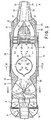
- Fig. 1 représente à une échelle réduite une section longitudinale d'un dispositif silencieux-épurateur d'échappement selon la présente invention;
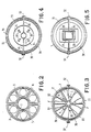
- Fig. 2 est une vue, prise suivant la flèche Il de la figure 1, de la deuxième entrée munie d'une soupape contre le retour;
- Fig. 3 représente une coupe faite selon la ligne brisée III - III de la figure 1, et elle montre en particulier le ventilateur d'aspiration;
- Fig. 4 représente une coupe faite selon la ligne IV - IV de la figure 1, et elle montre en particulier le brûleur;
- Fig. 5 est une vue axiale du dispositif du côté d'écoulement, prise suivant la flèche V de la figure 1.
- Par le numéro 0 est indiqué, dans la figure 1, un tronçon terminal d'un tuyau d'échappement, par exemple du moteur endothermique d'un véhicule, auquel est appliqué le dispositif silencieux-épurateur selon l'invention. Ce dispositif a une forme et des dimensions similaires de celles d'un pot d'échappement habituel, et par conséquent son installation ne comporte aucun problème particulier. Le tronçon 0 du tuyau d'échappement est inséré et fixé dans un élément tubulaire 1 constituant la première entrée du dispositif. Coaxialement autour de cette première entrée 1 est disposé un élément tubulaire 2 de plus grand diamètre, constituant la deuxième entrée destinée au passage de l'air additionnel, deuxième entrée que, le cas échéant, on disposera de sorte qu'elle soit saisie par le vent de la course afin qu'une pression de stagnation puisse agir sur elle. Dans l'élément tubulaire 2 est disposée une plaque de soupape 3 coopérant avec des segments 4 de soupape lamellaire protégés par des épaulements postérieurs courbes 5, pour former une soupape contre le retour permettant l'aspiration d'air, mais non son reflux accidentel. Cette unité d'aspiration est protégée extérieurement par une coquille 6 de tôle perforée ou de filet métallique.
- Derrière les débouchés concentriques des éléments d'entrée 1 et 2 est disposé un ventilateur en hélice à axe longitudinal 7, dans le cas présent à cinq palettes, dont l'axe est librement pivotant dans des paliers 8 et 10. Le palier 8 est supporté par des ailettes radiales 9 dans le premier élément d'entrée 1, et le palier 10 est supporté au centre d'une étoile d'ailettes 11 d'orientation du flux, ancrées périphériquement à l'enveloppe du dispositif, décrite plus avant. Avantageusement, des ailettes d'orientation similaires 12 sont disposées dans le débouché de l'élément tubulaire 2, qu'elles relient mécaniquemient avec l'élément coaxial d'entrée 1.
- En aval des ailettes 11 est disposée une chambre de postcombustion 14, dans la partie antérieure de laquelle est installé un brûleur 15. Ce dernier est constitué par un corps creux substantiellement sphéroïdal, en tôle d'acier inoxydable emboutie en deux coquilles qui s'étendent latéralement pour former des ailettes 16 servant à soutenir le brûleur 15. A partir des ailettes 11, la paroi interne de l'enveloppe du dispositif forme une section convergente 13 qui raccorde la section globale d'entrée du dispositif à la section plus réduite de passage disponible dans la chambre de postcombustion 14 autour du brûleur 15.
- Dans la partie antérieure du brûleur 15 sont formées des ouvertures 17, à travers lesquelles une partie du courant qui léche le brûleur peut pénétrer dans ce dernier. Dans la partie postérieure du brûleur sont montés des éléments thermiques 18, dans le cas présent sous la forme de bougies céramiques contenant des résistances électriques projetées et alimentées pour maintenir lesdites bougies à une température d'émission lumineuse, par exemple à 600°C. Le brûleur se termine postérieurement par au moins une ouverture d'écoulement 19, à travers laquelle il débouche dans la chambre de postcombustion 14.
- A l'extrémité arrière de la chambre de postcombustion 14 est installé un ensemble d'éléments catalytiques constitués par des disques 20 qui s'alternent avec des bagues 21; ces parties sont assemblées par des boulons longitudinaux 22, et les bagues 21 sont supportées périphériquement par l'enveloppe du dispositif. Les disques 20 et les bagues 21 sont formés, de préférence, par un fritté perméable de globules sphéroïdaux creux de cuivre ou d'un alliage de cuivre. Dans ce matériel, le rapport entre la surface exposée et le volume est très élevé, et par conséquence ce matériel est approprié pour être utilisé comme cataliseur efficace et, en outre, il présente des bonnes propriétés de filtration. Comme cataliseur, il agit efficacement, en particulier, sur les composés azotés et sulfurés, et comme élement filtrant il sépare les résidus pulvérulents, spécialement les oxydes de plomb et les composés sulfurés.
- Le dernier disque 20 porte un organe d'amortissement du bruit formé par une enveloppe effilée 23 en tôle perforée, dans lequel est enroulé, avec ses spires espacées, un ressort 24 en spirale de lame métallique, traversée elle aussi par des perforations. Cette structure forme une pluralité de chambres communiquantes, substantiellement ouvertes dans la direction du flux, qui exercent une action efficace d'atténuaton des vibrations, et par conséquent des bruits, sans opposer une résistance appréciable au flux de gaz.
- Le dispositif se termine par une ouverture d'écoulement qui, dans l'exemple représenté, est délimitée par deux éléments en canal 25 et 26, emboîtés l'un dans l'autre, articulés antérieurement en 27 à l'enveloppe du dispositif et poussés l'un vers l'autre par des ressorts en lame 28. Les éléments 25 et 26 peuvent se déplacer, quand la force des ressorts en lame 28 est vaincue, jusqu'à une position indiquée par une ligne a points et traits dans la figure 1, en augmentant alors la section d'écoulement du dispositif.
- Des passages 29 peuvent être prévus afin de permettre à l'air ambiant de se porter à lécher les élements en canal 25 et 26, en s'écoulant postérieurement autour du flux des gaz d'échappement sortant de ces éléments en canal. Ce flux d'air agit aussi dans le sens d'un refroidissement utile des ressorts 28.
- L'enveloppe du dispositif, laquelle renferme tous les composant décrits jusqu'ici, est formée substantiellement par deux coquilles en tôle emboutie, l'une inférieure 30 et l'autre supérieure 31, jointes lelong d'un plan axial horizontal et reliées l'une l'autre par des bordures 32. Cette disposition autorise un montage très facile de toute la structure, et les bordures 32 assurent aussi le reliage de certaines parties internes, telles que les ailettes 16 du brûleur 15. Si cela est considéré à propos, certaines parties de l'une des coquilles peuvent être rendues démontables, en remplaçant des tronçons de bordure par des reliages au mien de boulons, afin de permettre l'accès aux parti es internes mobiles, telles que le ventilateur 7 et les éléments en canal 25, 26, ou bien à d'autres parties dont on peut prévoir le remplacement. Les coquilles de l'enveloppe sont à parois doubles, et entre la parois externe et celle interne sont disposés des matériaux 33 acoustiquement et thermiquement isolants. Dans l'endroit de la chambre de postcombustion 14, qui représente une source de chaleur, on peut prévoir aussi une paroi extérieure 34 entourant à une certaine distance l'enveloppe 30 - 31 pour guider l'air à lécher l'enveloppe et à le refroidir efficacement.
- Le fonctionnement du dispositif décrit est le suivant. Les gaz d'échappement venant du moteur passent du tuyau d'échappement 0 à l'entrée tubulaire 1 et agissent sur le ventilateur 7 en le faisant tourner et par cela donnant lieu à l'aspiration d'un courant d'air additionnel à partir de l'entrée 2 à travers la soupape contre le retour 3 - 5. Les deux courants procèdent ensemble, orientés par les ailettes 11, mais au moins partiellement séparés par une stratification, avec des couches plus chaudes formées
- principalement par des gaz d'échappement à l'intérieur, et avec des couches plus froides formées principalement par de l'air additionnel à l'extérieur. Ces gaz arrivent à la chambre de postcombustion 14 en léchant le brûleur 15. Une partie des gaz d'échappement pénètre dans le brûleur 15 à travers les ouvertures 17 et, sous l'action thermique et l'effet photochimique des bougies 18 chauffées au rouge, subit une dissociation endothermique qui intéresse spécialement le bioxyde de carbone, et ensuite elle s'écoule à travers l'ouverture 19 en se mélangeant selon les flèches A avec le reste des gaz d'échappement et avec l'air additionnel qui se trouvent dans la chambre de postcombustion 14. Dans le mélange ainsi formé a lieu une recombinaison exothermique, spécialement du bioxyde de carbone, sous la forme d'une flamme très chaude qui propage au mélange présent tout entier une réaction conduisant à la combustion presque complète, à l'aide de l'oxygène de l'air additionnel, des substances imbrûlées et du monoxyde de carbone présents.
- Le mélange chaud et désormais épuré pour la plus grande partie arrive alors en contact avec les éléments catalytiques 20 et 21, en passant entr'eux et en les traversant partiellement, et il est soumis ici à une action de cracking catalytique qui décompose les derniers résidus de substances imbrûlées, à une action d'oxydation catalytique qui intéresse les résidus éventuels de monoxyde de carbone, à une action catalytique qui décompose les oxydes d'azote en les transformant en des éléments non contaminants, et à une action chimique qui transforme en des substances solides pulvérulentes les coposés sulfurés. L'ensemble des disques 20 et des bagues 21 constitue en même temps un abatteur de matières pulvérulentes qui fonctionne soit, partiellement, par filtration, grâce à la perméabilité des éléments catalytiques, soit par déviation du flux; de cette manière on obtient d'éliminer des gaz d'échappement, en particulier, les oxydes de plomb dérivant de la combustion des substances antidétonantes éventuellement contenues dans le combustible utilisé, et les composés sulfurés pulvérulents. En outre, le passage à travers les éléments catalytiques 20 et 21 donne encore lieu à une forte atténuation du bruit des gaz; ce bruit est enfin atténué ultérieurement par la lame métallique perforée 24 enroulée en spirale, laquelle donne lieu à cette atténuation sans une dispersion appréciable d'énergie.
- Enfin, les gaz sortent à travers les élements en canal 25 et 26. Les ressorts 28 son projetés de manière à équilibrer la pression exercée par les gaz d'échappement sur les éléments en canal 25 et 26 en des conditions moyennes de fonctionnement. Aux régimes plus élevés, cette pression augmente et provoque un éloignement réciproque des éléments en canal 25 et 26, en augmentant ainsi la section d'écoulement plutôt que la vitesse des gaz, et en réduisant donc avantageusement la contrepression à l'échappement.
- Quand on prévoit les passages 29, un flux laminaire d'air s'écoule autour du flux principal des gaz d'échappement, en formant ainsi une sorte de coussinet entre les gaz d'échappement et l'ambient, avec le résultat de réduire les turbulences, les résistances et le bruit, et de refroidir avantageusement les parties mobiles du raccord d'écoulement.
- En effet, les phénomènes sommairement décrits n'on pas un déroulement continu mais, en plusieurs conditions de fonctionnement, dans l'intérieur du dispositif s'établit un régime dynamque d'oscillations de pression qui se propagent alternativament dans les deux sens longitudinaux; la fonction de la soupape 3 - 5 contre le retour est précisément celle de réfléchir les ondes de pression quand elles viennent de l'intérieur, en empêchant leur reflux et en favorisant l'établissement dudit régime dynamique d'oscillations de pression, similaire de celui d'un pulsoréacteur.
- En vertu des caractéristiques et comportements décrits, le dispositif selon l'invention permet d'épurer d'une manière très efficace des gaz d'échappement, en éliminant les substances contaminantes qu'ils contiennent, et en même temps d'atténuer efficacement les vibrations et, par conséquent, les bruits. De ce fait, le dispositif selon l'invention, bien qu'il soit approprié pour des applications plus générales, est particulièrement utile pour épurer et rendre silencieux l'échappement de moteurs à combustion interne. Il faut remarquer que, pour les raisons indiquées ci-haut, le dispositif selon l'invention est capable d'épurer efficacement les échappements des moteurs Diesel et en général des installations dans lesquelles on brûle des huiles combustibles, qui jusqu'à maintenant étaient pratiquent exclues de toute possibilité d'épuration efficace.
- Un avantage spécial est obtenu dans l'application aux moteurs de ce genre montés sur des véhicules, car dans ce cas la poussée exercée par les gaz d'échappement s'écoulant du dispositif peut être utilisée pour fournir une poussée propulsive additionnelle. A cet égard on doit remarquer que la structure, décrite comme étant celle d'un silencieux-épurateur capable de fournir aussi une poussée propulsive, peut être aussi utilisée, si nécessaire, en donnant une plus grande importance à l'effet propulsif, en injectant opportunément dans la chambre de postcombustion un flux de combustible liquide, pulvérisé ou gazeux.
- Naturellement, des différentes modifications peuvent être portées aux composants décrits. Ainsi, par exemple, dans le brûleur on peut utiliser comme éléments thermiques, au lieu des bougies céramiques, d'autres types de résistances électriques spéciales, ou bien des éléments en barre ou d'une autre forme, chauffés par induction. Le corps du brûleur peut être réalisé en des matériaux différents de l'acier inoxydable, par exemple et avantageusement en quartz. Au lieu des éléments en canal décrits, le raccord d'écoulement peut présenter des autres dispositions à surface variable, par exemple un système à lamelles multiples similaire de celui qui est employé dans les échappements des turboréacteurs de propulsion.
Claims (18)
Applications Claiming Priority (2)
| Application Number | Priority Date | Filing Date | Title |
|---|---|---|---|
| IT6759784 | 1984-06-12 | ||
| IT67597/84A IT1179718B (it) | 1984-06-12 | 1984-06-12 | Silenziatore depuratore di scarico specialmente per motori a combustione interna |
Publications (2)
| Publication Number | Publication Date |
|---|---|
| EP0166480A1 EP0166480A1 (fr) | 1986-01-02 |
| EP0166480B1 true EP0166480B1 (fr) | 1989-01-25 |
Family
ID=11303742
Family Applications (1)
| Application Number | Title | Priority Date | Filing Date |
|---|---|---|---|
| EP85200876A Expired EP0166480B1 (fr) | 1984-06-12 | 1985-06-04 | Silencieux-épurateur d'échappement, spécialement pour des moteurs à combustion interne |
Country Status (4)
| Country | Link |
|---|---|
| EP (1) | EP0166480B1 (fr) |
| JP (1) | JPS6140410A (fr) |
| DE (1) | DE3567936D1 (fr) |
| IT (1) | IT1179718B (fr) |
Families Citing this family (13)
| Publication number | Priority date | Publication date | Assignee | Title |
|---|---|---|---|---|
| IT1232749B (it) * | 1989-04-12 | 1992-03-05 | I R T I Istituto Di Ricerca E | Depuratore di gas di scarico ad attivita`catalitica e silenziatore per motori a combustione interna |
| DE3933924A1 (de) * | 1989-10-11 | 1991-04-18 | Bayerische Motoren Werke Ag | Verfahren zur abgasnachbehandlung an einer brennkraftmaschine |
| US6165292A (en) * | 1990-12-18 | 2000-12-26 | Advanced Cardiovascular Systems, Inc. | Superelastic guiding member |
| FR2679602B1 (fr) * | 1991-07-26 | 1995-03-24 | Valeo Thermique Moteur Sa | Pot catalytique a support de catalyseurs en feuilles. |
| JP2603033B2 (ja) * | 1991-08-30 | 1997-04-23 | ブリッグス アンド ストラットン コーポレイション | 排気装置用マフラ |
| JP3310014B2 (ja) * | 1992-04-02 | 2002-07-29 | 黒田精工株式会社 | U軸機構連結装置 |
| DE19634367C1 (de) * | 1996-08-26 | 1998-04-02 | Daimler Benz Ag | Brennkraftmaschine mit einer Abgasleitung |
| WO2000071869A1 (fr) * | 1999-05-20 | 2000-11-30 | Makoto Nagahashi | Procede et mecanisme de regulation de gaz d'echappement |
| KR100403277B1 (ko) * | 2001-01-30 | 2003-10-30 | 김영만 | 자동차용 머플러 |
| US7572414B2 (en) * | 2001-10-09 | 2009-08-11 | Lummus Technology Inc. | Modular system and method for the catalytic treatment of a gas stream |
| JP2004138013A (ja) * | 2002-10-21 | 2004-05-13 | Suzuki Motor Corp | 排ガス浄化構造 |
| WO2009144533A1 (fr) * | 2008-05-30 | 2009-12-03 | Wickramasinghe Neville Saumyas | Buse turbo |
| CN107044327A (zh) * | 2017-03-28 | 2017-08-15 | 广西柳州方益建筑工程有限公司 | 一种刮灰排气管 |
Family Cites Families (8)
| Publication number | Priority date | Publication date | Assignee | Title |
|---|---|---|---|---|
| US2065681A (en) * | 1935-04-03 | 1936-12-29 | Livius V Fogas | Gas burner |
| US2985255A (en) * | 1959-09-08 | 1961-05-23 | Donald R Wilson | After-burner for internal combustion engine exhaust gases |
| US3603080A (en) * | 1969-06-25 | 1971-09-07 | Callaway As | Emmission control assembly |
| DE2163537A1 (de) * | 1971-12-21 | 1973-07-12 | Volkswagenwerk Ag | Verfahren zum aufheizen von abgasreinigungsanlagen |
| DE2212721A1 (de) * | 1972-03-16 | 1973-09-20 | 7100 Heilbronn | Abgasentgifungsanlage fuer verbrennungskraftmaschinen aller art |
| DE2418108C3 (de) * | 1974-04-13 | 1981-04-02 | UOP Inc., 60016 Des Plaines, Ill. | Thermisch-katalytische Abgas-Reinigungsvorrichtung |
| US4054418A (en) * | 1975-11-10 | 1977-10-18 | E. I. Du Pont De Nemours And Company | Catalytic abatement system |
| US4345431A (en) * | 1980-03-25 | 1982-08-24 | Shimizu Construction Co. Ltd. | Exhaust gas cleaning system for diesel engines |
-
1984
- 1984-06-12 IT IT67597/84A patent/IT1179718B/it active
-
1985
- 1985-06-04 DE DE8585200876T patent/DE3567936D1/de not_active Expired
- 1985-06-04 EP EP85200876A patent/EP0166480B1/fr not_active Expired
- 1985-06-11 JP JP12702785A patent/JPS6140410A/ja active Pending
Also Published As
| Publication number | Publication date |
|---|---|
| IT8467597A1 (it) | 1985-12-12 |
| DE3567936D1 (en) | 1989-03-02 |
| IT1179718B (it) | 1987-09-16 |
| EP0166480A1 (fr) | 1986-01-02 |
| IT8467597A0 (it) | 1984-06-12 |
| JPS6140410A (ja) | 1986-02-26 |
Similar Documents
| Publication | Publication Date | Title |
|---|---|---|
| EP0166480B1 (fr) | Silencieux-épurateur d'échappement, spécialement pour des moteurs à combustion interne | |
| JP4794595B2 (ja) | ディーゼルエンジンの排気装置 | |
| US3066755A (en) | Muffler with spiral partition | |
| US5285640A (en) | Integrated post-engine emissions heater, catalytic converter and muffler | |
| FR2902137A1 (fr) | Bruleur et procede pour la regeneration de cartouches de filtration et dispositifs equipes d'un tel bruleur | |
| EP0099828B1 (fr) | Dispositif pour la combustion de fluides combustibles avec induction d'air | |
| FR2488942A1 (fr) | Procede et appareil de combustion pour turbine a gaz | |
| FR2616886A1 (fr) | Chambre de combustion annulaire pour une turbine a gaz | |
| US3666422A (en) | Pollution control system | |
| EP1200177B1 (fr) | Systeme de neutralisation de gaz polluants par pyrolyse | |
| FR3107304A1 (fr) | Dispositif catalytique pour traitement des gaz d’echappement d’un moteur a combustion interne | |
| KR101323610B1 (ko) | 배기가스 승온용 버너장치 | |
| CA2237843C (fr) | Systeme de rechauffe dichotomique reduisant les pertes en sec | |
| US3059421A (en) | Apparatus for minimizing the combustible content of exhaust gases | |
| FR2820341A1 (fr) | Dispositif de traitement des gaz d'echappement d'un moteur a combustion interne comportant un catalyseur accumulateur | |
| EP0939207B1 (fr) | Nouvel élément catalytique destiné au traitement des gaz d'échappement d'un moteur à combustion interne | |
| JP4794594B2 (ja) | ディーゼルエンジンの排気装置 | |
| WO2008000975A1 (fr) | Bruleur pour realiser la combustion de substances reputees difficilement combustibles | |
| EP3710688B1 (fr) | Groupe motopropulseur avec systeme de depollution ameliore | |
| FR3075317A3 (fr) | Bruleur suralimenteur | |
| FR2766557A1 (fr) | Bruleurs a combustible liquide et gazeux a faible emission d'oxydes d'azote | |
| FR2921971A1 (fr) | Ligne d'echappement de moteur de vehicule automobile comportant un dispositif empechant un echauffement critique | |
| FR2717223A1 (fr) | Dispositif d'échappement pour moteur à combustion interne. | |
| FR2937082A1 (fr) | Bruleur pour regeneration des filtres a particules de moteur a combustion interne et la mise en temperature de systeme catalytique et ligne d'echappement integrant un tel bruleur. | |
| RU2175391C2 (ru) | Нейтрализатор отработавших газов |
Legal Events
| Date | Code | Title | Description |
|---|---|---|---|
| PUAI | Public reference made under article 153(3) epc to a published international application that has entered the european phase |
Free format text: ORIGINAL CODE: 0009012 |
|
| AK | Designated contracting states |
Designated state(s): CH DE FR GB LI SE |
|
| 17P | Request for examination filed |
Effective date: 19860517 |
|
| 17Q | First examination report despatched |
Effective date: 19870428 |
|
| GRAA | (expected) grant |
Free format text: ORIGINAL CODE: 0009210 |
|
| AK | Designated contracting states |
Kind code of ref document: B1 Designated state(s): CH DE FR GB LI SE |
|
| PG25 | Lapsed in a contracting state [announced via postgrant information from national office to epo] |
Ref country code: SE Effective date: 19890125 Ref country code: GB Free format text: LAPSE BECAUSE OF NON-PAYMENT OF DUE FEES Effective date: 19890125 |
|
| REF | Corresponds to: |
Ref document number: 3567936 Country of ref document: DE Date of ref document: 19890302 |
|
| GBV | Gb: ep patent (uk) treated as always having been void in accordance with gb section 77(7)/1977 [no translation filed] | ||
| PLBE | No opposition filed within time limit |
Free format text: ORIGINAL CODE: 0009261 |
|
| STAA | Information on the status of an ep patent application or granted ep patent |
Free format text: STATUS: NO OPPOSITION FILED WITHIN TIME LIMIT |
|
| 26N | No opposition filed | ||
| PGFP | Annual fee paid to national office [announced via postgrant information from national office to epo] |
Ref country code: DE Payment date: 19960723 Year of fee payment: 12 |
|
| PGFP | Annual fee paid to national office [announced via postgrant information from national office to epo] |
Ref country code: CH Payment date: 19960925 Year of fee payment: 12 |
|
| PGFP | Annual fee paid to national office [announced via postgrant information from national office to epo] |
Ref country code: FR Payment date: 19970623 Year of fee payment: 13 |
|
| PG25 | Lapsed in a contracting state [announced via postgrant information from national office to epo] |
Ref country code: LI Free format text: LAPSE BECAUSE OF NON-PAYMENT OF DUE FEES Effective date: 19970630 Ref country code: CH Free format text: LAPSE BECAUSE OF NON-PAYMENT OF DUE FEES Effective date: 19970630 |
|
| REG | Reference to a national code |
Ref country code: CH Ref legal event code: PL |
|
| PG25 | Lapsed in a contracting state [announced via postgrant information from national office to epo] |
Ref country code: DE Free format text: LAPSE BECAUSE OF NON-PAYMENT OF DUE FEES Effective date: 19980303 |
|
| PG25 | Lapsed in a contracting state [announced via postgrant information from national office to epo] |
Ref country code: FR Free format text: LAPSE BECAUSE OF NON-PAYMENT OF DUE FEES Effective date: 19990226 |
|
| REG | Reference to a national code |
Ref country code: FR Ref legal event code: ST |