EP0164530B1 - Oxygen sensor - Google Patents
Oxygen sensor Download PDFInfo
- Publication number
- EP0164530B1 EP0164530B1 EP85104699A EP85104699A EP0164530B1 EP 0164530 B1 EP0164530 B1 EP 0164530B1 EP 85104699 A EP85104699 A EP 85104699A EP 85104699 A EP85104699 A EP 85104699A EP 0164530 B1 EP0164530 B1 EP 0164530B1
- Authority
- EP
- European Patent Office
- Prior art keywords
- insulating part
- electrical
- sensing element
- electrically insulating
- test
- Prior art date
- Legal status (The legal status is an assumption and is not a legal conclusion. Google has not performed a legal analysis and makes no representation as to the accuracy of the status listed.)
- Expired
Links
- 239000001301 oxygen Substances 0.000 title claims description 38
- 229910052760 oxygen Inorganic materials 0.000 title claims description 38
- QVGXLLKOCUKJST-UHFFFAOYSA-N atomic oxygen Chemical compound [O] QVGXLLKOCUKJST-UHFFFAOYSA-N 0.000 title claims description 36
- 239000007789 gas Substances 0.000 claims description 60
- 238000010438 heat treatment Methods 0.000 claims description 38
- 239000007784 solid electrolyte Substances 0.000 claims description 25
- 239000004020 conductor Substances 0.000 claims description 12
- 239000010410 layer Substances 0.000 claims description 8
- 239000000919 ceramic Substances 0.000 claims description 4
- 238000009434 installation Methods 0.000 claims description 4
- 239000000463 material Substances 0.000 claims description 4
- 238000002485 combustion reaction Methods 0.000 claims description 2
- 229910052751 metal Inorganic materials 0.000 claims description 2
- 239000002184 metal Substances 0.000 claims description 2
- 239000011241 protective layer Substances 0.000 claims description 2
- -1 oxygen ions Chemical class 0.000 claims 1
- 238000007789 sealing Methods 0.000 description 9
- BASFCYQUMIYNBI-UHFFFAOYSA-N platinum Chemical compound [Pt] BASFCYQUMIYNBI-UHFFFAOYSA-N 0.000 description 6
- 238000010292 electrical insulation Methods 0.000 description 4
- 238000005259 measurement Methods 0.000 description 4
- TWNQGVIAIRXVLR-UHFFFAOYSA-N oxo(oxoalumanyloxy)alumane Chemical compound O=[Al]O[Al]=O TWNQGVIAIRXVLR-UHFFFAOYSA-N 0.000 description 4
- 238000000034 method Methods 0.000 description 3
- 229910052697 platinum Inorganic materials 0.000 description 3
- 238000005476 soldering Methods 0.000 description 3
- 238000003466 welding Methods 0.000 description 3
- FYYHWMGAXLPEAU-UHFFFAOYSA-N Magnesium Chemical compound [Mg] FYYHWMGAXLPEAU-UHFFFAOYSA-N 0.000 description 2
- MCMNRKCIXSYSNV-UHFFFAOYSA-N ZrO2 Inorganic materials O=[Zr]=O MCMNRKCIXSYSNV-UHFFFAOYSA-N 0.000 description 2
- 229910010293 ceramic material Inorganic materials 0.000 description 2
- 239000003792 electrolyte Substances 0.000 description 2
- 230000007774 longterm Effects 0.000 description 2
- 229910052749 magnesium Inorganic materials 0.000 description 2
- 239000011777 magnesium Substances 0.000 description 2
- 238000004519 manufacturing process Methods 0.000 description 2
- RVTZCBVAJQQJTK-UHFFFAOYSA-N oxygen(2-);zirconium(4+) Chemical compound [O-2].[O-2].[Zr+4] RVTZCBVAJQQJTK-UHFFFAOYSA-N 0.000 description 2
- 230000001681 protective effect Effects 0.000 description 2
- 238000005245 sintering Methods 0.000 description 2
- 229910052596 spinel Inorganic materials 0.000 description 2
- 239000011029 spinel Substances 0.000 description 2
- PNEYBMLMFCGWSK-UHFFFAOYSA-N aluminium oxide Inorganic materials [O-2].[O-2].[O-2].[Al+3].[Al+3] PNEYBMLMFCGWSK-UHFFFAOYSA-N 0.000 description 1
- 230000004888 barrier function Effects 0.000 description 1
- 239000011324 bead Substances 0.000 description 1
- 230000001419 dependent effect Effects 0.000 description 1
- 238000011161 development Methods 0.000 description 1
- 230000018109 developmental process Effects 0.000 description 1
- 230000000694 effects Effects 0.000 description 1
- 230000035784 germination Effects 0.000 description 1
- 239000011521 glass Substances 0.000 description 1
- PCHJSUWPFVWCPO-UHFFFAOYSA-N gold Chemical compound [Au] PCHJSUWPFVWCPO-UHFFFAOYSA-N 0.000 description 1
- 239000010931 gold Substances 0.000 description 1
- 229910052737 gold Inorganic materials 0.000 description 1
- 150000002926 oxygen Chemical class 0.000 description 1
- 239000002245 particle Substances 0.000 description 1
- 238000003825 pressing Methods 0.000 description 1
- 230000000284 resting effect Effects 0.000 description 1
- 239000007787 solid Substances 0.000 description 1
Images

Classifications
-
- G—PHYSICS
- G01—MEASURING; TESTING
- G01N—INVESTIGATING OR ANALYSING MATERIALS BY DETERMINING THEIR CHEMICAL OR PHYSICAL PROPERTIES
- G01N27/00—Investigating or analysing materials by the use of electric, electrochemical, or magnetic means
- G01N27/26—Investigating or analysing materials by the use of electric, electrochemical, or magnetic means by investigating electrochemical variables; by using electrolysis or electrophoresis
- G01N27/403—Cells and electrode assemblies
- G01N27/406—Cells and probes with solid electrolytes
- G01N27/4067—Means for heating or controlling the temperature of the solid electrolyte
Definitions
- the invention is based on an oxygen sensor according to the preamble of the main claim. It's already a
- Oxygen sensor known corresponds to EP-A-0 056 837
- an electrical heating element with a rod-shaped, ceramic heating element carrier is installed in the interior of its tubular sensor element; in this oxygen sensor the internal structure, which is influenced by the heating element and its electrical connections, is relatively complicated and consequently expensive; the area of the oxygen sensor which relates to the radiator and its electrical supply lines is moreover not particularly resistant to shaking in the long term and is therefore not reliable.
- an oxygen sensor (DE-A-3 056 608) with a wire-shaped heating element which is wound helically around the solid electrolyte tube provided with a measuring electrode and an electrical insulating layer arranged thereon.
- the solid electrolyte tube is provided with an open longitudinal slot extending into its interior, through which the connecting wires of the heating coil are guided; the connecting wires run in the interior first through a seal, for example made of glass, and then through longitudinal channels in an electrical insulating part in the direction of the sensor connection area.
- a seal for example made of glass
- the oxygen sensor according to the invention with the features of claim 1 has the advantage that its internal structure is simpler, consequently also easier to assemble and therefore cheaper overall. Another advantage is that the embodiment of the oxygen sensor according to the invention is more robust and more resistant to shaking than the oxygen sensors mentioned under the section "State of the art".
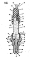
- FIG. 1 shows a longitudinal section through a first embodiment of an oxygen sensor according to the invention in an enlarged view
- FIG. 2 shows a longitudinal section through the measuring gas-side end section of the electrical insulating part with the electric radiator of the oxygen sensor according to FIG. 1 in a further enlarged illustration
- FIG. 3 shows a longitudinal section through a second embodiment of an oxygen sensor according to the invention in an enlarged view.
- the oxygen sensor 10 shown in Figures 1 and 2 of the drawing has a metallic housing 11 which has on its outside a key hexagon 12 and a thread 13 as a fastening means for installation in a measuring gas tube, not shown; for the sealing installation of this housing 11 in the measuring gas tube, an annular sealing element 14 is used, which is captively fixed in an annular groove 15 arranged between the hexagon socket 12 and the thread 13.
- an annular groove 16 is also incorporated, which serves to fix the housing 11 to the closure sleeve 17; this closure sleeve 17, which has a bottom 18 remote from measuring gas, with a central opening 19 is fixed in the annular groove 16 by means of a plurality of impressions 20.
- the housing 11 has a longitudinal bore 21 with a shoulder 22 which faces away from the measuring side of the oxygen sensor 10 and carries an annular metallic sealing element 23.
- a sensor element 24 with its head 25 rests on this shoulder 22 of the housing longitudinal bore 21 provided with the sealing element 23.
- this sensor element 24 is an oxygen sensor known per se, as is known from DE-U-8 101 584 and which is preferably used for measuring the oxygen partial pressure in exhaust gases from internal combustion engines and furnace systems.
- This sensor element 24 has a solid electrolyte tube 26 consisting of zirconium dioxide, the measuring gas side of which End portion is closed by a bottom 27; On its outside exposed to the measuring gas, this solid electrolyte tube 26 carries a layered, gas-permeable measuring electrode 28 and on its side facing the interior 29 it is provided with a layered counter or reference electrode 30 which is exposed to a reference gas (e.g. air) and is gas-permeable .
- a reference gas e.g. air
- the solid electrolyte tube 26 consisting entirely of an oxygen-ion-conducting material such as zirconium dioxide, it can also be constructed in such a way that only the measuring range consists of oxygen-ion-conducting material and the remaining section is made of a different material, preferably a different ceramic material (e.g. Aluminum oxide) is formed.
- the measuring electrode 28 is in contact with the electrically grounded housing 11 via the annular sealing element 23, the reference electrode 30 preferably leads from the inside of the base 27 to the front surface 31 of the solid electrolyte tube 26, which is remote from the measuring gas, and forms here on a partial area of the front surface 31 a contact area 32.
- an electrical insulation layer which can consist, for example, of aluminum oxide, but is not particularly shown in the drawing.
- a convex fixing lug 33 is integrally formed on the end surface 31 of the solid electrolyte tube 26 remote from the measuring gas.
- the portion of the sensor element 24 protruding from the longitudinal bore 21 of the housing 11 on the measuring gas side is surrounded at a distance by a protective tube 34 which has openings 35 for the entry and exit of measuring gases and on the measuring gas side end of the housing 11 by a flange 36 or another known means for this is specified;
- This protective tube 34 serves to ensure that high temperature changes occurring in the measuring gas and particles contained in the measuring gas do not act directly on the sensor element 24 and lead to damage to it.
- the interior 29 of the solid electrolyte tube 26 is essentially filled by a rod-shaped, electrical heating element 37 which extends on the measuring gas side to close to the bottom 27 of the solid electrolyte tube 26 and is integrally formed on an electrical insulating part 38 away from the measuring gas.
- This electrical insulating part 38 with its protruding into the interior 29 of the solid electrolyte tube 26 support 39 for the actual heating element 40 is preferably made of ceramic such as. B. alumina.
- the heating element 40 is preferably designed as a conductor track which is located essentially in the area of the solid electrolyte tube 26 which forms the measuring area of the sensor element 24.
- This heating element 40 which can be made of platinum, for example, is guided via corresponding conductor tracks 41 up to a shoulder 42 of the electrical insulating part 38, which is formed between the heating element carrier 39 and the actual electrical insulating part 38.
- the sections of the heating element feed lines 41 located in the area of this shoulder 42 are somewhat thickened in a preferred embodiment and thus form contact areas 43; In the illustrated embodiment of the electrical insulating part 38, these contact areas 43 are arranged in fixing troughs 44 of the shoulder 42, which extend radially in the direction of the heating element carrier 39.
- the conductor track-like heating element 40 and its electrical supply lines 41 are covered - excluding the contact areas 43 - by means of an electrical insulating layer 45, which may consist, for example, of aluminum oxide or magnesium spinel.
- the radiator 37 consisting of carrier 39, heating element 40 and electrical insulation layer 45 largely fills the interior 29 of the solid electrolyte tube 26.
- the measuring gas side end section of the heating element carrier 39 is provided with a sack-shaped axial bore 46, as a result of which the measuring gas side end section of the heating element carrier 39 has a reduced volume to be heated.
- This axial bore 46 can also serve for fixing in the manufacture of the electrical insulating part 38 including its heating element carrier 39, which is particularly advantageous when printing on the heating element 40 and its supply lines 41.
- the contact ends 47 of wire-shaped connecting means 48 On the contact areas 43 of the heating element 40 lie the contact ends 47 of wire-shaped connecting means 48, which are bent at right angles and lead through longitudinal bores 49 through the electrical insulating part 38.
- the contact ends 47 of the connecting means 48 rest on the end face 31 of the solid electrolyte tube 26, but in areas which are electrically insulated from the contact area 32 of the reference electrode 30 which also ends here.
- a wire-shaped connecting means 51 which extends in a longitudinal bore 52 of the electrical insulating part 38 and, as with the connecting means 48 for the heating element 40, with its end portion remote from the measuring gas from the end surface 53 remote from the measuring gas Electrical insulating part 38 protrudes.
- a fixing hole 54 is also formed, into which the fixing lug 33 protruding from the end face 31 of the solid electrolyte tube 26 is inserted so that the contact ends 47 and 50 of the connecting means 48 and 51 are held in the correct position.
- a fixing lug 33 with a corresponding fixing hole 54 depressions can also be provided in the end face 31 of the solid electrolyte tube 24, into which the contact ends 47 and 50 protrude, respectively; in all these or similar solutions, however, the contact ends 47 and 50 must be securely clamped between the shoulder 42 of the electrical insulating part 38 and the end face 31 of the solid electrolyte tube 26.
- the electrical insulating part 38 is essentially cylindrical, preferably consists of ceramic material (e.g. aluminum oxide) and, with its section adjoining the heating element 37 remote from the measuring gas, projects into a bore 55 in the end section of the housing longitudinal bore 21 remote from the measuring gas.
- ceramic material e.g. aluminum oxide
- the measuring gas-side end section of a metallic guide sleeve 56 which coaxially surrounds the electrical insulating part 38, also projects into this bore 55; this guide sleeve 56 can be fixed in the bore 55 of the housing 11 by pressing, caulking, soldering or the like and has at its end remote from the measuring gas an outwardly facing flange 57 which extends laterally close to the closure sleeve 17; the annular space 58 formed between this guide sleeve 56 and the sealing sleeve 17 acts as a barrier to moisture which can enter the oxygen sensor 10 in the region between the measuring gas-side end section of the sealing sleeve 17 and the housing 11 with the air serving as reference gas.
- Spring element 59 (disc spring) is arranged, which is supported on the one hand on the bottom 18 of the closure sleeve 17 and, on the other hand, rests under mechanical prestress on a coaxial shoulder 60 of the electrical insulating part 38 which points away from the measuring side of the oxygen sensor 10.
- the electrical insulating part 38 is pressed with the contact ends 47 and 50 resting against its shoulder 42 on the measuring gas side in the direction of the end surface 31 of the solid electrolyte tube 26 remote from the measuring gas, and thus causes the contact pressures required in this area.
- a metallic connecting sleeve 61 is pushed and by a known method such. B. crushing, soldering, welding fixed;
- the connecting sleeves 61 stand with their measuring gas side end on the end face 53 of the electrical insulating part 38.
- the end sections of the connecting sleeves 61 remote from the measuring gas comprise the stripped end sections of connecting wires 62 and 63 for the reference electrode 30 and for the heating element 37 of the oxygen sensor 10; these stripped, measuring gas-side end sections of the connecting wires 62 and 63 are fastened in the connecting sleeves 61 by squeezing, welding and / or soldering.
- the measuring gas-side end face 64 of an elastic insulating plug 65 stands on the end surface 53 of the electrical insulating part 38 remote from the measuring gas, and the longitudinal wires 66, 63 including the connecting sleeves 61 are sealingly encompassed by the longitudinal through holes 66 thereof.
- this insulating plug 65 is equipped with a flange part 67, the measuring surface on the measuring gas side of which protrudes sealingly on the outside of the closure sleeve base 18; the measuring gas-side end face 64 of the insulating plug 65 is preferably arranged in a coaxial recess 69 of the flange part 67 which receives the end section of the electrical insulating part 38 remote from the measuring gas.
- a tubular, preferably metallic, head sleeve 71 is arranged on the outer surface 70 of this insulating plug, and its widened end section on the measuring gas side engages closely over the end section of the closure sleeve 17 remote from the measuring gas; the head sleeve 71 is fixed to the closure sleeve 17 by means of some welding spots 72 or other known fastening means and holds the insulating plug 65 in the longitudinal direction of the oxygen sensor 10 under mechanical pretension.
- one of these connecting means can alternatively be saved in that the electrical return line of the heating element 40 is formed via a conductor track section, not shown, which is formed by the end face 31 of the Solid electrolyte tube 26 is guided to the sealing element 23 and consequently connects the contact area 43, which is used for the electrical return line and is located on the shoulder 42 of the electrical insulating part 38, to the housing 11, which is electrically grounded.
- FIG. 3 shows an embodiment of an oxygen sensor 10 'in which the sensor element 24' differs from the sensor element 24 according to the example in FIG. 1 in that the interior 29 'of the solid electrolyte tube 26' is not sealed off from the measurement gas, but rather that the sample gas is made accessible through an opening 73 in the solid electrolyte tube 26 '.
- the measuring electrode 28' consists in a known manner of a material (e.g. platinum) which is more catalytically active than the material (e.g. gold) of the reference electrode 30 'located on the inside of the residual electrolyte tube 26'.
- the other structure of the sensor element 24 ' corresponds to the sensor element 24 according to FIG. 1.
- This sensor element 24' is installed in a metal housing 11 ', which differs from the housing 11 according to FIG. 1 in that its end section remote from the measuring gas has a flange 74 and a annular heat shrink area 75 is provided.
- the section of the electrical insulating part 38 ' formed as a head 76 and which forms a coaxial, annular shoulder 78 with the shaft 77 of the electrical insulating part 38' is arranged.
- On this shoulder 78 is a crimp ring 79, on which the crimp edge 74 of the housing 11 'presses.
- this electrical insulating part head 76 On the measurement side there is an axially extending blind hole 81, in which the end section of a mold body carrier 39 'remote from the measurement gas is fixed (eg by sintering).
- a type of combination of electrical insulating part 38 'and radiator support 39' can be expedient for sintering reasons, but can also be used to influence the thermal conductivity.
- the arrangement and design of the heating element, not shown in FIG. 3, including its feed lines and the electrical insulation layer, corresponds to the exemplary embodiment according to FIGS. 1 and 2.
- a connecting sleeve 61 ' is soldered into each of the three blind holes 82, the preferably solid section of which protrudes into the respective blind hole 82 and the section remote from the measuring gas comprises the stripped end of a connecting wire 62' or 63 '; the conductor track-like connecting means 51 'for the reference electrode 30' of the sensor element 24 'and also the conductor tracks of the heating element 37' not shown in this FIG. 3 are covered on the electrical insulating part 38 'by means of an electrical insulating layer, not shown, so that only the contact area 32' the end face 80 of the electrical insulating part 38 'and the areas located in the blind holes 82 thereof remain uncovered.
- annular grooves 83 are formed, in which corresponding ring beads 84 engage in a sealing manner, which are arranged coaxially in a measuring gas-side recess 69' of an insulating plug 65 '.
- this insulating plug 65 ' is firmly enclosed in a known manner by a metallic head sleeve 71'; the measurement-side, tubular end section of this head sleeve 71 'is preferably provided with longitudinal expansion slots 85 which are open towards the measurement gas-side end of the head sleeve 71'.
- an electrically insulated conductor track part (not shown) can be used, which is connected to the housing 11 'via the head 25' of the solid electrolyte tube 26 '. of the oxygen sensor 10 'is connected.
- supports can be used instead of a rod-shaped support 39' with a round cross section, which have a different cross-section (e.g. rectangular).
- the electrical insulating part 38 ' is provided with a fixing hole 34' in the face 80 on the measuring gas side, into which a fixing lug 33 'engages to fix the sensor element 24' in the correct position and which engages on the end face 31 'of the solid electrolyte tube 26' is molded on.
Landscapes
- Chemical & Material Sciences (AREA)
- Life Sciences & Earth Sciences (AREA)
- Health & Medical Sciences (AREA)
- Physics & Mathematics (AREA)
- Chemical Kinetics & Catalysis (AREA)
- Electrochemistry (AREA)
- Molecular Biology (AREA)
- Analytical Chemistry (AREA)
- Biochemistry (AREA)
- General Health & Medical Sciences (AREA)
- General Physics & Mathematics (AREA)
- Immunology (AREA)
- Pathology (AREA)
- Measuring Oxygen Concentration In Cells (AREA)
Description
Die Erfindung geht aus von einem Sauerstoffmeßfühler nach der Gattung des Hauptanspruchs. Es ist schon einThe invention is based on an oxygen sensor according to the preamble of the main claim. It's already a
Sauerstoffmeßfühler bekannt (DE-U-8 101 584, entspricht EP-A-0 056 837), bei dem im Innenraum seines rohrförmigen Sensorelementes ein elektrischer Heizkörper mit einem stabförmigen, keramischen Heizelement-Träger eingebaut ist; bei diesem Sauerstoffmeßfühler ist der innere, durch den Heizkörper und dessen elektrischen Verbindungen beeinflußte Aufbau aber relativ kompliziert und demzufolge teuer; der den Heizkörper und dessen elektrische Zuleitungen betreffende Bereich des Sauerstoffmeßfühlers ist darüber hinaus auf Dauer nicht besonders schüttelfest und demzufolge nicht betriebssicher.Oxygen sensor known (DE-U-8 101 584, corresponds to EP-A-0 056 837), in which an electrical heating element with a rod-shaped, ceramic heating element carrier is installed in the interior of its tubular sensor element; in this oxygen sensor the internal structure, which is influenced by the heating element and its electrical connections, is relatively complicated and consequently expensive; the area of the oxygen sensor which relates to the radiator and its electrical supply lines is moreover not particularly resistant to shaking in the long term and is therefore not reliable.
Bekannt ist auch bereits ein Sauerstoffmeßfühler (DE-A-3 056 608) mit einem drahtförmigen Heizelement, das wendelförmig um das mit einer Meßelektrode und einer darauf angeordneten Elektroisolierschicht versehene Festelektrolytrohr geschlungen ist. Das Festelektrolytrohr ist mit einem bis in seinen Innenraum durchgehenden offenen Längsschlitz versehen, durch welchen die Anschlußdrähte der Heizwendel geführt sind; die Anschlußdrähte verlaufen im Innenraum zunächst durch eine beispielsweise aus Glas bestehende Dichtung und dann durch Längskanäle in einem Elektroisolierteil in Richtung des Meßfühler-Anschlußbereiches. Die Anordnung hat aus Kosten- , Funktions- und Zuverlässigkeitsgründen die auf Dauer erwarteten Ansprüche nicht erfüllt.Also known is an oxygen sensor (DE-A-3 056 608) with a wire-shaped heating element which is wound helically around the solid electrolyte tube provided with a measuring electrode and an electrical insulating layer arranged thereon. The solid electrolyte tube is provided with an open longitudinal slot extending into its interior, through which the connecting wires of the heating coil are guided; the connecting wires run in the interior first through a seal, for example made of glass, and then through longitudinal channels in an electrical insulating part in the direction of the sensor connection area. For cost, function and reliability reasons, the arrangement did not meet the long-term expectations.
Der erfindungsgemäße Sauerstoffmeßfühler mit den Merkmalen des Anspruchs 1 hat demgegenüber den Vorteil, daß sein innerer Aufbau einfacher gestaltet, demzufolge auch problemloser montierbar und deshalb insgesamt billiger ist. Als weiterer Vorteil ist anzusehen, daß die erfindungsgemäße Ausführungsform des Sauerstoffmeßfühlers robuster und schüttelfester ist als die unter dem Abschnitt "Stand der Technik" genannten Sauerstoffmeßfühler.The oxygen sensor according to the invention with the features of claim 1 has the advantage that its internal structure is simpler, consequently also easier to assemble and therefore cheaper overall. Another advantage is that the embodiment of the oxygen sensor according to the invention is more robust and more resistant to shaking than the oxygen sensors mentioned under the section "State of the art".
Durch die in den abhängigen Ansprüchen aufgehührt Maßnahmen sind vorteilhafte Weiterbildungen und Verbesserungen des Anspruch 1 angegebenen Sauerstoffmeßfühlers möglich. Besonders vorteilhaft ist es, wenn der Träger des Heizkörpers direkt an das Elektroisolierteil mit angeformt ist, denn die Herstellung derartiger Meßfühler wird durch diese Maßnahme noch weiter verbilligt und die Schüttelfestigkeit dieser Meßfühler auch noch weiter erhöht. Sofern die elektrischen Zuleitungen zum Heizkörper und gegebenenfalls auch zumindestens einer Elektrode des Sauerstoffmeßfühlers auf dem Elektroisolierteil als elektrisch isolierte Leiterbahnen ausgebildet sind, lassen sich die letztgenannten Vorteile noch weiter verbessern.The measures listed in the dependent claims allow advantageous further developments and improvements of the oxygen sensor indicated in claim 1. It when the support of the radiator is molded directly onto the electrical insulating part is particularly advantageous, because the manufacture of such sensors is made even cheaper by this measure and the resistance to shaking of these sensors is also further increased. If the electrical leads to the radiator and possibly also at least one electrode of the oxygen sensor on the electrical insulating part are designed as electrically insulated conductor tracks, the latter advantages can be further improved.
Ausführungsbeispiele der Erfindung sind in der Zeichnung dargestellt und in der nachfolgenden Beschreibung näher erläutert. Es zeigen Figur 1 einen Längsschnitt durch eine erste Ausführungsform eines erfindungsgemäßen Sauerstoffmeßfühlers in vergrößerter Darstellung, Figur 2 einen Langsschnitt durch den meßgasseitigen Endabschnitt des Elektroisolierteils mit dem elektrischen Heizkorper des Sauerstoffmeßfühlers nach Figur 1 in noch weiter vergrößerter Darstellung und Figur 3 einen Längsschnitt durch eine zweite Ausführungsform eines erfindungsgemäßen Sauerstoffmeßfühlers in vergrößerter Darstellung.Embodiments of the invention are shown in the drawing and explained in more detail in the following description. FIG. 1 shows a longitudinal section through a first embodiment of an oxygen sensor according to the invention in an enlarged view, FIG. 2 shows a longitudinal section through the measuring gas-side end section of the electrical insulating part with the electric radiator of the oxygen sensor according to FIG. 1 in a further enlarged illustration, and FIG. 3 shows a longitudinal section through a second embodiment of an oxygen sensor according to the invention in an enlarged view.
Der in den Figuren 1 und 2 der Zeichnung dargestellte Sauerstoffmeßfühler 10 hat ein metallisches Gehäuse 11, das an seiner Außenseite ein Schlüsselsechskant 12 und ein Gewinde 13 als Befestigungsmittel für den Einbau in ein nicht dargestelltes Meßgasrohr aufweist; für den abdichtenden Einbau dieses Gehäuses 11 in dem Meßgasrohr dient ein ringförmiges Dichtelement 14, das in einer zwischen Schlüsselsechskant 12 und Gewinde 13 angeordneten Ringnut 15 unverlierbar festgelegt ist. Auf dem meßgasfernen Endabschnitt des Gehäuses 11 ist noch eine Ringnut 16 eingearbeitet, die zur Festlegung einer das Gehäuse 11 Verlängern den Verschlußhülse 17 dient; diese Verschlußhülse 17, welche meßgasfern einen Boden 18 mit einer zentralen Öffnung 19 hat, ist mittels mehrerer Einprägungen 20 in der Ringnut 16 Festgelegt.The
Das Gehäuse 11 hat eine Längsbohrung 21 mit einer Schulter 22, die der Meßseite des Sauerstoffmeßfühlers 10 abgewendet ist und ein ringförmiges metallisches Dichtelement 23 trägt. Auf dieser mit dem Dichtelement 23 versehenen Schulter 22 der Gehäuse-Längsbohrung 21 liegt ein Sensorelement 24 mit seinem Kopf 25 auf.The
Dieses Sensorelement 24 ist-im vorliegenden Beispiel ein an sich bekannter Sauerstoffmeßfühler, wie er aus der DE-U-8 101 584 bekannt ist und der bevorzugterweise für das Messen des Sauerstoffpartialdruckes in Abgasen von Brennkraftmaschinen und Ofenanlagen Verwendung findet. Dieses Sensorelement 24 hat ein aus Zirkondioxid bestehendes Festelektrolytrohr 26, dessen meßgasseitiger Endabschnitt mittels eines Bodens 27 verschlossen ist; auf seiner dem Meßgas ausgesetzten Außenseite trägt dieses Festelektrolytrohr 26 eine schichtförmige, gasdurchlässige Meßelektrode 28 und auf seiner dem Innenraum 29 zugewendeten Seite ist es mit einer schichtförmigen Gegen- oder Bezugselektrode 30 versehen, welche einem Referenzgas (z. B. Luft) ausgesetzt und gasdurchlässig ist. Zur Erhöhung der Lebensdauer der zumeist aus einer dünnen Platinschicht bestehenden Meßelektrode 28 ist diese bekannterweise mit einer gasdurchlässigen (nicht dargestellten) Schutzschicht überzogen, die beispielsweise aus Magnesiumspinell bestehen kann.In the present example, this
Anstelle dessen, daß das Festelektrolytrohr 26 vollständig aus einem Sauerstoffionen leitendem Material wie Zirkondioxid besteht, kann es auch so aufgebaut sein, daß nur der Meßbereich aus sauerstoffionenleitendem Material besteht und der verbleibende Abschnitt von einem anderen Material, bevorzugt einem anderen keramischem Material (z. B. Aluminiumoxid) gebildet wird. Während die Meßelektrode 28 über das ringförmige Dichtelement 23 mit dem elektrisch an Masse liegenden Gehäuse 11 in Berührung steht, führt die Bezugselektrode 30 bevorzugterweise von der Innenseite des Bodens 27 bis auf die meßgasferne Stirnfläche 31 des Festelektrolytrohres 26 und bildet hier auf einem Teilbereich der Stirnfläche 31 einen Kontaktbereich 32. Zwischen dem Kontaktbereich 32 der Bezugselektrode 30 und der Stirnfläche 31 des Fastelektrolytrohres 26 befindet sich vorteilhafterweise eine Elektroisolierschicht, welche beispielsweise aus Aluminiumoxid bestehen kann, aber in der Zeichnung nicht besonders dargestellt ist. An die meßgasferne Stirnfläche 31 des Festelektrolytrohres 26 ist eine konvexe Fixiernase 33 mit angeformt, deren Funktion später beschrieben wird.Instead of the
Der meßgasseits aus der Längsbohrung 21 des Gehäuses 11 herausragende Abschnitt des Sensorelementes 24 ist mit Abstand von einem Schutzrohr 34 umgeben, welches für den Ein- bzw. Austritt von Meßgasen Öffnungen 35 besitzt und am meßgasseitigen Ende des Gehäuses 11 durch eine Bördelung 36 oder ein anderes hierfür bekanntes Mittel festgelegt ist; dieses Schutzrohr 34 dient dazu, daß im Meßgas auftretende hohe Temperaturwechsel und im Meßgas enthaltene Partikel nicht direkt auf das Sensorelement 24 einwirken und zu Schäden daran führen.The portion of the
Der Innenraum 29 des Festelektrolytrohres 26 ist im wesentlichen durch einen stabförmigen, elektrischen Heizkörper 37 ausgefüllt, welcher meßgasseits bis nahe an den Boden 27 des Festelektrolytrohres 26 reicht und meßgasfern einteilig an ein Elektroisolierteil 38 angeformt ist. Dieses Elektroisolierteil 38 mit seinem in den Innenraum 29 des Festelektrolytrohres 26 hineinragenden Träger 39 für das eigentliche Heizelement 40 besteht vorzugsweise aus Keramik wie z. B. Aluminiumoxid. Das Heizelement 40 wird in bevorzugter Weise als Leiterbahn ausgebildet, die sich im wesentlichen in demjenigen Bereich des Festelektrolytrohres 26 befindet, welcher den Meßbereich des Sensorelementes 24 bildet. Dieses Heizelement 40, das beispielsweise aus Platin bestehen kann, ist über entsprechende leiterbahnförmige Zuleitungen 41 bis auf eine Schulter 42 des Elektroisolierteiles 38 geführt, die zwischen dem Heizelement-Träger 39 und dem eigentlichen Elektroisolierteil 38 gebildet ist. Die im Bereich dieser Schulter 42 befindlichen Abschnitte der Heizelement-Zuleitungen 41 sind in bevorzugter Ausführungsform etwas verdickt und bilden somit Kontaktbereiche 43; bei der dargestellten Ausführungsform des Elektroisolierteiles 38 sind diese Kontaktbereiche 43 in Fixiermulden 44 der Schulter 42 angeordnet, die sich radial in Richtung Heizelement-Träger 39 erstrecken. Das leiterbahnartige Heizelement 40 und seine elektrischen Zuleitungen 41 sind - ausschließlich der Kontaktbereiche 43 - mittels einer Elektroisolierschicht 45 abgedeckt, die beispielsweise aus Aluminiumoxid oder Magnesiumspinell bestehen kann. Der aus Träger 39, Heizelement 40 und Elektroisolierschicht 45 bestehende Heizkörper 37 füllt weitgehend den Innenraum 29 des Festelektrolytrohres 26 aus. Um ein möglichst schnelles Aufheizen des Heizkörpers 37 in demjenigen Bereich des Sensorelementes 24 zu bewirken, in welchem der eigentliche Meßvorgang stattfindet, ist der meßgasseitige Endabschnitt des Heizelement-Trägers 39 mit einer sackförmigen Axialbohrung 46 versehen, infolge welcher der meßgasseitige Endabschnitt des Heizelement-Trägers 39 ein verringertes aufzuheizendes Volumen besitzt. Diese Axialbohrung 46 kann bei der Herstellung des Elektroisolierteils 38 einschließlich seines Heizelement-Trägers 39 auch zur Fixierung dienen, was insbesondere beim Aufdrucken des Heizelementes 40 und dessen Zuleitungen 41 von besonderem Vorteil ist.The
Auf den Kontaktbereichen 43 des Heizelementes 40 liegen die rechtwinklig abgebogenen Kontaktenden 47 von drahtförmigen Verbindungsmitteln 48 auf, welche durch Längsbohrungen 49 durch das Elektroisolierteil 38 hindurchführen. Meßgasseits liegen die Kontaktenden 47 der Verbindungsmittel 48 auf der Stirnfläche 31 des Festelektrolytrohres 26 auf, jedoch in Bereichen, welche gegenüber dem Kontaktbereich 32 der hier auch endenden Bezugselektrode 30 elektrisch isoliert sind.On the
Auf dem Kontaktbereich 32 für die Bezugselektrode 30 liegt ebenfalls ein abgewinkeltes Kontaktende Steines drahtförmigen Verbindungsmittels 51 auf, welches in einer Längsbohrung 52 des Elektroisolierteils 38 verläuft und wie auch bei den Verbindungsmitteln 48 für das Heizelement 40 - mit seinem meßgasfernen Endabschnitt aus der meßgasfernen Stirnfläche 53 des Elektroisolierteils 38 herausragt.On the
In der Schulter 42 des Elektroisolierteiles 38 ist ein Fixierloch 54 mit eingeformt, in welches die aus der Stirnfläche 31 des Festelektrolytrohres 26 herausragende Fixiernase 33 derart hineinfaßt, so daß die Kontaktenden 47 und 50 der Verbindungsmittel 48 und 51 in der richtigen Lage gehalten werden. Anstelle einer solchen Fixiernase 33 mit einem entsprechenden Fixierloch 54 können aber auch in der Stirnfläche 31 des Festelektrolytrohres 24 (nicht dargestellte) Vertiefungen vorgesehen werden, in welche die Kontaktenden 47 bzw. 50 fixierend hineinragen; bei all diesen oder ähnlichen Lösungen müssen jedoch die Kontaktenden 47 und 50 zwischen der Schulter 42 des Elektroisolierteiles 38 und der Stirnfläche 31 des Festelektrolytrohres 26 sicher eingeklemmt sein.In the
Das Elektroisolierteil 38 ist im wesentlichen zylinderförmig, besteht vorzugsweise aus keramischem Material (z. B. Aluminiumoxid) und ragt mit seinem sich dem Heizkörper 37 meßgasfern anschließenden Abschnitt in eine Aufbohrung 55 des meßgasfernen Endabschnitts der Gehäuselängsbohrung 21 hinein. In diese Aufbohrung 55 ragt auch der meßgasseitige Endabschnitt einer metallischen Führungshülse 56 hinein, welche das Elektroisolierteil 38 koaxial umgibt; diese Führungshülse 56 kann in der Aufbohrung 55 des Gehäuses 11 durch Einpressen, Verstemmen, Löten oder ähnliches festgelegt sein und hat an ihrem meßgasfernen Ende einen nach außen weisenden Flansch 57, der seitlich bis nahe an die Verschlußhülse 17 reicht; der zwischen dieser Führungshülse 56 und der Verschlußhülse 17 gebildete Ringraum 58 wirkt als Barriere gegenüber Feuchtigkeit, die im Bereich zwischen dem meßgasseitigen Endabschnitt der Verschlußhülse 17 und dem Gehäuse 11 mit der als Referenzgas dienenden Luft in den Sauerstoffmeßfühler 10 eintreten kann. Zwischen dem Flansch 57 der Führungshülse 56 und dem Boden 18 der Verschlußhülse 17 ist ein ringförmiges. Federelement 59 (Tellerfeder) angeordnet, daß sich einerseits an dem Boden 18 der Verschlußhülse 17 abstützt und andererseits unter mechanischer Vorspannung auf einer von der Meßseite des Sauerstoffmeßfühlers 10 wegweisenden, koaxialen Schulter 60 des Elektroisolierteils 38 aufliegt. Infolge der mechanischen Vorspannung des Federelementes 59 wird das Elektroisolierteil 38 mit den an seiner meßgasseitigen Schulter 42 anliegenden Kontaktenden 47 und 50 in Richtung auf die meßgasferne Stirnfläche 31 des Festelektrolytrohres 26 gedruckt und bewirkt derart die in diesem Bereich erforderlichen Kontaktdrücke.The electrical
Auf jeden der meßgasfern aus dem Elektroisolierteil 38 herausragenden Endabschnitte der Verbindungsmittel 48 und 51 ist eine metallische Verbindungshülse 61 aufgeschoben und mittels eines bekannten Verfahrens wie z. B. Verquetschen, Verlöten, Verschweißen festgelegt; die Verbindungshülsen 61 stehen mit ihrem meßgasseitigem Ende auf der Stirnfläche 53 des Elektroisolierteils 38 auf. Die meßgasfernen Endabschnitte der Verbindungshülsen 61 umfassen die abisolierten Endabschnitte von Anschlußdrähten 62 und 63 fur die Bezugselektrode 30 bzw. für den Heizkörper 37 des Sauerstoffmeßfühlers 10; diese abisolierten, meßgasseitigen Endabschnitte der Anschlußdrähte 62 und 63 sind in den Verbindungshülsen 61 durch Verquetschen, Verschweißen und/oder Verlöten befestigt.On each of the measuring gas distant from the electrical insulating
Außer den Verbindungshülsen 61 steht auf der meßgasfernen Stirnfläche 53 des Elektroisolierteiles 38 die meßgasseitige Stirnfläche 64 eines elastischen Isolierstopfens 65 auf, von dessen längsverlaufenden Durchgangsbohrungen 66 die Anschußdrähte 62, 63 einschließlich der Verbindungshülsen 61 abdichtend umfaßt werden. Meßgasseits ist dieser Isolierstopfen 65 mit einem Flanschteil 67 ausgestattet, dessen meßgasseitige Endfläche 68 auf der Aussenseite des Verschlußhülsen-Bodens 18 abdichtend aufsteht; die meßgasseitige Stirnfläche 64 des Isolierstopfens 65 ist dabei in bevorzugter Weise in einer koaxialen Aussparung 69 des Flanschteils 67 angeordnet, welche den meßgasfernen Endabschnitt des Elektroisolierteils 38 aufnimmt. Auf der Mantelfläche 70 dieses Isolierstopfens ist eine rohrförmige, vorzugsweise metallische Kopfhülse 71 angeordnet, die mit ihrem aufgeweiteten, meßgasseitigen Endabschnitt eng über den meßgasfernen Endabschnitt der Verschlußhülse 17 greift; die Kopfhülse 71 ist an der Verschlußhülse 17 mittels einiger Schweißpunkte 72 oder anderer bekannter Befestigungsmittel festgelegt und halt den Isolierstopfen 65 in Längsrichtung des Sauerstoffmeßfühlers 10 unter mechanischervorspannung.In addition to the connecting
Anstelle, daß für den elektrischen Anschluß des Heizelementes 40 zwei drahtförmige Verbindungsmittel 48 durch den Sauerstoffmeßfühler 10 hindurchführen, kann alternativ eines dieser Verbindungsmittel dadurch eingespart werden, daß die elektrische Rückleitung des Heizelementes 40 über einen nicht dargestellten Leiterbahnabschnitt gebildet wird, welcher von der Stirnfläche 31 des Festelektrolytrohres 26 bis zum Dichtelement 23 geführt ist und demzufolge den der elektrischen Rückleitung dienenden, auf der Schulter 42 des Elektroisolierteils 38 befindlichen Kontaktbereich 43 mit dem elektrisch an Masse liegenden Gehäuse 11 verbindet.Instead of two wire-
In der Figur 3 ist eine Ausführungsform eines Sauerstoffmeßfühlers 10' dargestellt, bei dem sich das Sensorelement 24' von dem Sensorelement 24 gemäß dem i3eispiel in Figur 1 dadurch unterscheidet, daß der Innenraum 29' des Festelektrolytrohres 26' nicht gegenüber dem Meßgas abgedichtet ist, sondern daß dem Meßgas über einen Durchbruch 73 im Festelektrolytrohr 26' der Zutritt ermöglicht wird. Bei einer solchen Art von Sauerstoffmeßfühler 10' besteht die Meßelektrode 28' in bekannter Weise aus einem Material (z. B. Platin), das katalytisch aktiver ist als das Material (z. B. Gold) der auf der Innenseite des restelektrolytrohres 26' befindlichen Bezugselektrode 30'. Der sonstige Aufbau des Sensorelementes 24' entspricht dem Sensorelement 24 gemäß Figur 1. Dieses Sensorelement 24' ist in ein Metallgehäuse 11' eingebaut, welches sich von dem Gehäuse 11 gemäß Figur 1 dadurch unterscheidet, daß sein meßgasferner Endabschnitt mit einem Bördelrand 74 und mit einem ringförmigen Warmschrumpfbereich 75 versehen ist. In der meßgasfernen Aufbohrung 55' der Gehäuse-Längsbohrung 21' ist der als Kopf 76 ausgebildete meßgasseitige Abschnitt des Elektroisolierteiles 38' angeordnet, welcher mit dem Schaft 77 des Elektroisolierteils 38' eine koaxiale, ringförmige Schulter 78 bildet. Auf dieser Schulter 78 liegt ein Bördelring 79 auf, auf welchen der Bördelrand 74 des Gehäuses 11' aufdrückt. In der meßseitigen Stirnseite 80 dieses Elektroisolierteil-Kopfes 76 befindet sich ein axial verlaufendes Sackloch 81, in welchem der meßgasferne Endabschnitt eines Keizkörper-Trägers 39' festgelegt ist (z. B. durch Einsintern). Eine solche Art der Kombination von Elektroisolierteil 38' und Heizkörper-Träger 39' kann aus sintertechnischen Gründen zweckmäßig sein, kann aber auch zur Beeinflussung der Wärmeleitfähigkeit Anwendung finden. Die Anordnung und Gestaltung des in dieser Figur 3 nicht dargestellten Heizelementes einschließlich seiner Zuleitungen und der Elektroisolierschicht entspricht dem Ausführungsbeispiel gemäß der Figuren 1 und 2.FIG. 3 shows an embodiment of an oxygen sensor 10 'in which the
Auf der meßgasseitigen Stirnseite 80 des Elektroisolierteiles 38' sind als elektrisches Verbindungsmittel 51' für die Bezugselektrode 30' des Sensorelementes 24' und auch für die in dieser Figur 3 nicht dargestellten Heizelement-Zuleitungen Leiterbahnen angeordnet, welche auf der Außenseite des Elektroisolierteiles 38' bis hinauf auf die meßgasferne Stirnfläche 53' und bevorzugterweise noch in je ein in dieser Stirnfläche 53' befindliches Sackloch 82 hineinführen. In die drei Sacklöcher 82 ist je eine Verbindungshülse 61' eingelötet, deren vorzugsweise massiver Abschnitt in das jeweilige Sackloch 82 hineinragt und deren meßgasferner Abschnitt das abisolierte Ende je eines Anschlußdrahtes 62' bzw. 63' umfaßt; die leiterbahnartigen Verbindungsmittel 51' für die Bezugselektrode 30' des Sensorelementes 24' und auch die in dieser Figur 3 nicht dargestellten Leiterbahnen des Heizkörpers 37' sind auf den Elektroisolierteil 38' derart mittels einer nicht dargestellten Elektroisolierschicht abgedeckt, so daß nur der Kontaktbereich 32' auf der Stirnseite 80 des Elektroisolierteiles 38' und die in den Sacklöchern 82 befindlichen Bereiche davon unbedeckt bleiben. Infolge der Anordnung des Bördelrandes 74 und des an sich bekannten Warmschrumpfverfahrens, welches im Warmschrumpfbereich 75 des Gehäuses 11' zur Auswirkung kommt, wird die Stirnseite 80 des Elektroisolierteiles 38' fest auf die meßgasferne Stirnfläche 31' des Festelektrolytrohres 26' gedrückt und damit auch die elektrische Verbindung zwischen dem Kontaktbereich 32' der Bezugselektrode 30' des Sensorelementes 24' mit dem leiterbahnartigen Verbindungsmittel 51' hergestellt.On the measuring gas side 80 of the electrical insulating part 38 'there are arranged as electrical connecting means 51' for the reference electrode 30 'of the
Auf der Mantelfläche des meßgasfernen Endabschnitts vom Elektroisolierteil 38' sind Ringnuten 83 eingeformt, in welche entsprechende Ringwülste 84 abdichtend eingreifen, welche koaxial in einer meßgasseitigen Aussparung 69' eines Isolierstopfens 65' angeordnet sind. Durch diesen gummielastischen Isolierstopfen 65' führen in Längsrichtung Durchgangsbohrungen 66', welche die Verbindungshülsen 61' einschließlich der Anschlußdrähte 62', 63' abdichtend umfassen. Die Mantelfläche dieses Isolierstopfens 65' ist in bekannter Weise von einer metallischen Kopfhülse 71' fest umfaßt; der meßseitige, rohrförmige Endabschnitt dieser Kopfhülse 71' ist in bevorzugter Weise mit längsverlaufenden Spreizschlitzen 85 versehen, welche zum meßgasseitigen Ende der Kopfhülse 71' hin offen sind.On the lateral surface of the end section remote from the measuring gas of the electrical insulating part 38 ', annular grooves 83 are formed, in which corresponding
Es sei erwähnt, daß auch bei einem solchen Sauerstoffmeßfühler 10' anstelle einer als elektrische Rückleitung des Keizkörpers 37' dienenden Leiterbahn ein elektrisch isoliertes Leiterbahnteil (nicht dargestellt) Verwendung finden kann, welche über den Kopf 25' des Festelektrolytrohres 26' mit dem Gehäuse 11' des Sauerstoffmeßfühlers 10' verbunden ist. Infolgedessen, daß der Träger 39' des Heizkörpers 37' zunächst als separates Teil hergestellt und dann in das Sackloch 81 des Elektroisolierteiles 38' eingebaut wird, ist es auch möglich, daß anstelle eines stabförmigen Trägers 39' mit rundem Querschnitt auch Träger Verwendung finden können, welche einen anderen Querschnitt haben (z. B. rechteckig).It should be mentioned that even with such an oxygen sensor 10 ', instead of a conductor track serving as an electrical return line for the germination element 37', an electrically insulated conductor track part (not shown) can be used, which is connected to the housing 11 'via the head 25' of the
Wie auch bei dem Beispiel des Sauerstoffmeßfühlers 10 gemäß der Figuren 1 und 2 ist das Elektroisolierteil 38' mit einem Fixierloch 34' in der meßgasseitigen Stirnseite 80 versehen, in welches zur lagerichtigen Fixierung des Sensorelementes 24' eine Fixiernase 33' hineingreift, die an die Stirnfläche 31' des Festelektrolytrohres 26' mit angeformt ist.As also in the example of the
Claims (6)
Applications Claiming Priority (2)
| Application Number | Priority Date | Filing Date | Title |
|---|---|---|---|
| DE3418142 | 1984-05-16 | ||
| DE19843418142 DE3418142A1 (en) | 1984-05-16 | 1984-05-16 | OXYGEN PROBE |
Publications (2)
| Publication Number | Publication Date |
|---|---|
| EP0164530A1 EP0164530A1 (en) | 1985-12-18 |
| EP0164530B1 true EP0164530B1 (en) | 1988-07-20 |
Family
ID=6235988
Family Applications (1)
| Application Number | Title | Priority Date | Filing Date |
|---|---|---|---|
| EP85104699A Expired EP0164530B1 (en) | 1984-05-16 | 1985-04-18 | Oxygen sensor |
Country Status (5)
| Country | Link |
|---|---|
| US (1) | US4609454A (en) |
| EP (1) | EP0164530B1 (en) |
| JP (1) | JPS60244855A (en) |
| AU (1) | AU569795B2 (en) |
| DE (2) | DE3418142A1 (en) |
Families Citing this family (14)
| Publication number | Priority date | Publication date | Assignee | Title |
|---|---|---|---|---|
| US5167785A (en) * | 1989-10-07 | 1992-12-01 | Mccready David F | Thin electrodes |
| US5139639A (en) * | 1991-03-08 | 1992-08-18 | General Motors Corporation | Electrochemical type exhaust gas oxygen sensor |
| JP3522357B2 (en) * | 1994-09-19 | 2004-04-26 | 日本特殊陶業株式会社 | Oxygen sensor |
| US5571397A (en) * | 1995-07-05 | 1996-11-05 | Ford Motor Company | Boron nitride exhaust seal |
| US6039856A (en) * | 1997-04-23 | 2000-03-21 | Robert Bosch Gmbh | Measuring device |
| JP3994561B2 (en) * | 1998-08-12 | 2007-10-24 | 株式会社デンソー | Gas sensor |
| DE19853601A1 (en) * | 1998-11-20 | 2000-05-25 | Bosch Gmbh Robert | Production of insulating layer for heater for probe for determining oxygen concentration in gas mixture, e.g. internal combustion engine exhaust gas involves sintering barium and/or strontium oxide with alumina |
| JP2006337341A (en) * | 2005-06-06 | 2006-12-14 | Hitachi Ltd | Oxygen sensor |
| US20080206107A1 (en) * | 2007-02-23 | 2008-08-28 | Honeywell International Inc. | Gas sensor apparatus for automotive exhaust gas applications |
| US7805992B2 (en) * | 2007-03-27 | 2010-10-05 | Honeywell International Inc. | Gas sensor housing for use in high temperature gas environments |
| JP5463788B2 (en) * | 2009-08-18 | 2014-04-09 | 富士通株式会社 | Ion analyzer and ion analysis method |
| DE102013205037A1 (en) * | 2013-03-21 | 2014-09-25 | Robert Bosch Gmbh | Sensor element and exhaust gas sensor comprising a sensor element |
| CN106996803B (en) * | 2016-01-25 | 2019-03-19 | 中国航发常州兰翔机械有限责任公司 | A sensor fixture with adjustable length and its working method |
| US11002700B2 (en) | 2017-11-21 | 2021-05-11 | Honeywell International Inc. | High temperature gas sensor |
Family Cites Families (11)
| Publication number | Priority date | Publication date | Assignee | Title |
|---|---|---|---|---|
| US550686A (en) * | 1895-12-03 | Electric cigar-lighter | ||
| US2030937A (en) * | 1933-01-05 | 1936-02-18 | Siemens Ag | Incandescent igniter |
| DE2729475A1 (en) * | 1977-06-30 | 1979-01-11 | Bosch Gmbh Robert | ELECTROCHEMICAL SENSOR FOR DETERMINING THE OXYGEN CONTENT IN EXHAUST GASES, IN PARTICULAR IN EXHAUST GASES FROM COMBUSTION ENGINES |
| US4175019A (en) * | 1978-04-03 | 1979-11-20 | General Motors Corporation | Heated solid electrolyte oxygen sensor |
| DE2942494A1 (en) * | 1979-10-20 | 1981-04-30 | Bosch Gmbh Robert | HEATABLE SENSOR FOR COMPONENTS OF GASES, ESPECIALLY IN EXHAUST GASES FROM COMBUSTION ENGINES |
| DE3035608A1 (en) * | 1980-09-20 | 1982-05-06 | Robert Bosch Gmbh, 7000 Stuttgart | Electrochemical measurement sensor for exhaust gas oxygen content - contains solid electrolyte tube with inner and outer electrodes |
| DE8101584U1 (en) * | 1981-01-23 | 1981-06-25 | Robert Bosch Gmbh, 7000 Stuttgart | "ELECTROCHEMICAL PROBE FOR DETERMINING THE OXYGEN CONTENT IN GASES" |
| JPS58166252A (en) * | 1982-03-26 | 1983-10-01 | Toyota Motor Corp | Oxygen sensor element having ceramic heater and its manufacture |
| US4415878A (en) * | 1982-09-30 | 1983-11-15 | Ford Motor Company | Partial pressure of oxygen sensor-III |
| US4526672A (en) * | 1984-03-23 | 1985-07-02 | Axia Incorporated | Oxygen sensor |
| US4847113A (en) * | 1988-02-26 | 1989-07-11 | The Oakland Corporation | Thread lock |
-
1984
- 1984-05-16 DE DE19843418142 patent/DE3418142A1/en not_active Withdrawn
-
1985
- 1985-04-18 EP EP85104699A patent/EP0164530B1/en not_active Expired
- 1985-04-18 DE DE8585104699T patent/DE3563883D1/en not_active Expired
- 1985-05-07 US US06/731,466 patent/US4609454A/en not_active Expired - Fee Related
- 1985-05-14 JP JP60100669A patent/JPS60244855A/en active Pending
- 1985-05-15 AU AU42588/85A patent/AU569795B2/en not_active Ceased
Also Published As
| Publication number | Publication date |
|---|---|
| DE3563883D1 (en) | 1988-08-25 |
| US4609454A (en) | 1986-09-02 |
| AU569795B2 (en) | 1988-02-18 |
| DE3418142A1 (en) | 1985-11-21 |
| JPS60244855A (en) | 1985-12-04 |
| AU4258885A (en) | 1986-11-20 |
| EP0164530A1 (en) | 1985-12-18 |
Similar Documents
| Publication | Publication Date | Title |
|---|---|---|
| EP0132691B1 (en) | Gas sensor | |
| EP0133486B1 (en) | Gas sensor | |
| EP0168589B1 (en) | Oxygen sensor | |
| EP0164530B1 (en) | Oxygen sensor | |
| EP0701693B1 (en) | Gas sensor | |
| DE2937048C2 (en) | Electrochemical measuring sensor for determining the oxygen content in gases, especially in exhaust gases from internal combustion engines | |
| EP0087626A2 (en) | Gas sensor, especially for gases of combustion engines | |
| DE2907032A1 (en) | ELECTROCHEMICAL PROBE FOR DETERMINING THE OXYGEN CONTENT IN GAS, ESPECIALLY IN EXHAUST GAS FROM COMBUSTION ENGINES | |
| WO1994029710A9 (en) | JOINT FOR THE DETECTION ELEMENT OF A GAS SENSOR | |
| WO1992008127A1 (en) | Gas measurement probe, especially for determining the oxygen content in internal combustion engine exhaust gases | |
| DE2942494A1 (en) | HEATABLE SENSOR FOR COMPONENTS OF GASES, ESPECIALLY IN EXHAUST GASES FROM COMBUSTION ENGINES | |
| EP1797411A1 (en) | Particle sensor and method for operating the same | |
| DE3509195C2 (en) | ||
| EP0056837B1 (en) | Electrochemical sensing element for oxygen measurement in gases | |
| DE2841771A1 (en) | ELECTROCHEMICAL PROBE FOR DETERMINING THE OXYGEN CONTENT IN GASES | |
| EP0938669A1 (en) | Gas sensor | |
| EP0151795A2 (en) | Polarographic oxygen sensor | |
| EP1611436A1 (en) | Sensor | |
| DE3035608A1 (en) | Electrochemical measurement sensor for exhaust gas oxygen content - contains solid electrolyte tube with inner and outer electrodes | |
| DE4034072A1 (en) | Gas sensor measuring oxygen@ content in exhaust gases - has contact portion support and plug opposite wall as insulating components parallel to sensor | |
| DE19534918C2 (en) | Sensor for measuring gas concentrations | |
| DE2350253C3 (en) | Electrochemical probe | |
| DE102004056417A1 (en) | Gas sensor | |
| DE9014826U1 (en) | Gas sensors, in particular for determining the oxygen content in exhaust gases from internal combustion engines | |
| DE102008055129A1 (en) | Gas sensor for use as lambda sensor for determining e.g. concentration of oxygen in exhaust gas of internal combustion engine, has holder part, where electrical connection from contact surface to connecting contact is produced by part |
Legal Events
| Date | Code | Title | Description |
|---|---|---|---|
| PUAI | Public reference made under article 153(3) epc to a published international application that has entered the european phase |
Free format text: ORIGINAL CODE: 0009012 |
|
| 17P | Request for examination filed |
Effective date: 19850418 |
|
| AK | Designated contracting states |
Designated state(s): DE FR GB IT |
|
| 17Q | First examination report despatched |
Effective date: 19870514 |
|
| GRAA | (expected) grant |
Free format text: ORIGINAL CODE: 0009210 |
|
| AK | Designated contracting states |
Kind code of ref document: B1 Designated state(s): DE FR GB IT |
|
| GBT | Gb: translation of ep patent filed (gb section 77(6)(a)/1977) | ||
| REF | Corresponds to: |
Ref document number: 3563883 Country of ref document: DE Date of ref document: 19880825 |
|
| ET | Fr: translation filed | ||
| ITF | It: translation for a ep patent filed | ||
| PLBE | No opposition filed within time limit |
Free format text: ORIGINAL CODE: 0009261 |
|
| STAA | Information on the status of an ep patent application or granted ep patent |
Free format text: STATUS: NO OPPOSITION FILED WITHIN TIME LIMIT |
|
| 26N | No opposition filed | ||
| PGFP | Annual fee paid to national office [announced via postgrant information from national office to epo] |
Ref country code: GB Payment date: 19910408 Year of fee payment: 7 |
|
| ITTA | It: last paid annual fee | ||
| PGFP | Annual fee paid to national office [announced via postgrant information from national office to epo] |
Ref country code: FR Payment date: 19910430 Year of fee payment: 7 |
|
| PGFP | Annual fee paid to national office [announced via postgrant information from national office to epo] |
Ref country code: DE Payment date: 19910625 Year of fee payment: 7 |
|
| PG25 | Lapsed in a contracting state [announced via postgrant information from national office to epo] |
Ref country code: GB Effective date: 19920418 |
|
| GBPC | Gb: european patent ceased through non-payment of renewal fee | ||
| PG25 | Lapsed in a contracting state [announced via postgrant information from national office to epo] |
Ref country code: FR Effective date: 19921230 |
|
| PG25 | Lapsed in a contracting state [announced via postgrant information from national office to epo] |
Ref country code: DE Effective date: 19930101 |
|
| REG | Reference to a national code |
Ref country code: FR Ref legal event code: ST |