EP0164525A1 - Réacteur nucléaire intégré de faibles dimensions, à eau pressurisée - Google Patents
Réacteur nucléaire intégré de faibles dimensions, à eau pressurisée Download PDFInfo
- Publication number
- EP0164525A1 EP0164525A1 EP85104570A EP85104570A EP0164525A1 EP 0164525 A1 EP0164525 A1 EP 0164525A1 EP 85104570 A EP85104570 A EP 85104570A EP 85104570 A EP85104570 A EP 85104570A EP 0164525 A1 EP0164525 A1 EP 0164525A1
- Authority
- EP
- European Patent Office
- Prior art keywords
- wall
- pressurized water
- water reactor
- enclosure
- steam
- Prior art date
- Legal status (The legal status is an assumption and is not a legal conclusion. Google has not performed a legal analysis and makes no representation as to the accuracy of the status listed.)
- Granted
Links
Images


Classifications
-
- G—PHYSICS
- G21—NUCLEAR PHYSICS; NUCLEAR ENGINEERING
- G21C—NUCLEAR REACTORS
- G21C1/00—Reactor types
- G21C1/04—Thermal reactors ; Epithermal reactors
- G21C1/06—Heterogeneous reactors, i.e. in which fuel and moderator are separated
- G21C1/08—Heterogeneous reactors, i.e. in which fuel and moderator are separated moderator being highly pressurised, e.g. boiling water reactor, integral super-heat reactor, pressurised water reactor
-
- G—PHYSICS
- G21—NUCLEAR PHYSICS; NUCLEAR ENGINEERING
- G21C—NUCLEAR REACTORS
- G21C1/00—Reactor types
- G21C1/32—Integral reactors, i.e. reactors wherein parts functionally associated with the reactor but not essential to the reaction, e.g. heat exchangers, are disposed inside the enclosure with the core
- G21C1/322—Integral reactors, i.e. reactors wherein parts functionally associated with the reactor but not essential to the reaction, e.g. heat exchangers, are disposed inside the enclosure with the core wherein the heat exchanger is disposed above the core
-
- G—PHYSICS
- G21—NUCLEAR PHYSICS; NUCLEAR ENGINEERING
- G21C—NUCLEAR REACTORS
- G21C1/00—Reactor types
- G21C1/32—Integral reactors, i.e. reactors wherein parts functionally associated with the reactor but not essential to the reaction, e.g. heat exchangers, are disposed inside the enclosure with the core
- G21C1/326—Integral reactors, i.e. reactors wherein parts functionally associated with the reactor but not essential to the reaction, e.g. heat exchangers, are disposed inside the enclosure with the core wherein the heat exchanger is disposed next to or beside the core
-
- G—PHYSICS
- G21—NUCLEAR PHYSICS; NUCLEAR ENGINEERING
- G21C—NUCLEAR REACTORS
- G21C1/00—Reactor types
- G21C1/32—Integral reactors, i.e. reactors wherein parts functionally associated with the reactor but not essential to the reaction, e.g. heat exchangers, are disposed inside the enclosure with the core
- G21C1/328—Integral reactors, i.e. reactors wherein parts functionally associated with the reactor but not essential to the reaction, e.g. heat exchangers, are disposed inside the enclosure with the core wherein the prime mover is also disposed in the vessel
-
- Y—GENERAL TAGGING OF NEW TECHNOLOGICAL DEVELOPMENTS; GENERAL TAGGING OF CROSS-SECTIONAL TECHNOLOGIES SPANNING OVER SEVERAL SECTIONS OF THE IPC; TECHNICAL SUBJECTS COVERED BY FORMER USPC CROSS-REFERENCE ART COLLECTIONS [XRACs] AND DIGESTS
- Y02—TECHNOLOGIES OR APPLICATIONS FOR MITIGATION OR ADAPTATION AGAINST CLIMATE CHANGE
- Y02E—REDUCTION OF GREENHOUSE GAS [GHG] EMISSIONS, RELATED TO ENERGY GENERATION, TRANSMISSION OR DISTRIBUTION
- Y02E30/00—Energy generation of nuclear origin
- Y02E30/30—Nuclear fission reactors
Definitions
- the present invention relates to a pressurized water nuclear reactor that is of compact design and is capable of being shop fabricated and shipped to a remote location as an integral unit.
- the principal components of the reactor and the nuclear steam supply system should be incorporated into a single pressure vessel. While attempts have previously been made to produce such a reactor, commercial acceptability is lacking.
- U.S. Patent 3,150,051 shows a packaged reactor with an integral superheater and pressurizer and an annular space containing a boiler means
- U.S. Patent 3,255,088 discloses an integral pressurized water reactor with a removable cover and removable heat transfer tube bundles which cooperate with inlet headers and outlet chambers in the side of the reactor vessel
- U.S. Patent 3,255,089 which illustrates another design with a different heat transfer means
- U.S. Patent 3,888,734 describes a small reactor that uses an integral steam generator carried by a closure means for the vessel.
- the present invention resides in a compact unitized pressurized water reactor comprising a pressure vessel, a core, a heat exchanger, a pump, and duct structures, characterized in that the pressure vessel is formed as a hollow cylindrical member having spaced inner and outer walls forming an annular hollow section, said annular hollow section being sealed at the top and bottom thereof, the inner wall of said pressure vessel forming an internal chamber within the vessel; said pressure vessel having a bottom wall sealing the bottom of said internal chamber; a removable closure means sealing the top of said internal chamber, and top closure means being affixed to the top of said inner wall and extending partially into said internal chamber; a core support means comprising a downwardly depending cylindrical primary coolant baffle positioned within said chamber; a nuclear core supported within said cylindrical primary coolant baffle at a location spaced from said bottom wall; opposed dividing walls extending between said inner and outer walls upwardly from the bottom; opposed channel members extending between said inner and outer walls, said channel members having conduits therein communicating between the top portion of said
- a pressurizer is formed integral with the pressure vessel, being formed in the upper portion of the annular hollow space, with a separator plate and heating means positioned in the upper portion.
- the pressure vessel is formed from upper and lower mating sections, such that the tube sheets and heat transfer tubes may be removed and replaced.
- an enclosure is fitted either over the hot legs of the heat transfer tubes with means to direct primary coolant from the inner chamber through the enclosure and hot legs, or an enclosure is fitted over the cold legs of the heat transfer tubes with means to direct primary coolant from the cold legs to a second enclosure containing a circulating pump, and then through conduit means for return to the chamber. Sealing means are provided for the enclosures to prevent bypass or leakage of the primary coolant from the directed path of flow.
- a small unitized pressurized water reactor 1 which is formed from a hollow cylindrical pressure vessel 3.
- the hollow cylindrical pressure vessel has an inner wall 5 and a spaced outer wall 7 which forms an annular space 9 therebetween, the annular space 9 being sealed by an annular top wall 11 and an annular bottom wall 13.
- the inner wall 5 of the pressure vessel 3 forms an internal chamber 15 within the vessel, and a bottom wall 17 seals off the bottom of the chamber 15.
- a removable closure means 19 such as a deep beam head, seals the inner chamber 15 and is affixed to the inner wall 5 such as by a bolted, gasketed, flanged joint 21.
- the removable closure means, affixed to the inner wall 5 extends partially into the chamber 15, while an upper open annular space 23 is maintained about the top portion of the pressure vessel 3.
- the inner wall 5 has an inwardly extending shoulder 25 near the upper portion thereof, which shoulder 25 positions a core support means, comprising a downwardly depending cylindrical primary coolant baffle 27, within the chamber 15. Supported within the core support means 27 there is a nuclear core 29, the core 29 positioned at a location spaced from the bottom wall 17. An upper reactor internal package, partially illustrated at 30, is also positioned within the chamber 15 above the core 29. A perforated support plate 31, at the bottom of the primary coolant baffle 27, permits the passage of primary coolant therethrough and upwardly through the core 29 within the primary coolant baffle 27.
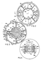
- opposed dividing walls 33 are provided between the inner wall 5 and the outer wall 7 in the annular space 9. These dividing walls 33 extend upwardly from the annular bottom wall 13, to a location spaced from the top wall 11, and affixed to the top of divider walls 33 is a circular sealing plate 35.
- the circular sealing plate 35 extends about the pressure vessel 3 and seals the upper portion 37 of the annular space 9 from the lower portion 39 thereof ( Figures 1 and 2).
- Opposed channel members 41 comprised of spaced walls 42, are also provided between the inner and outer walls 5 and 7, such that the divider walls 33 and channel members 41 form a plurality of compartments 10 in the lower portion 39 of the annular space 9.
- the walls 42 of the channel members also extend from the annular bottom wall 13 to the circular sealing plate 35, and have perforations in the lower portion for flow of secondary coolant therethrough.
- Conduit means 85 at the upper area of the channel members 41, communicate between the upper portion 37 of the annular space 9 and the region 43 between the inner wall 5 of the pressure vessel 3 and the outer surface 45 of the primary coolant baffle 27.
- the sealing plate 35 in the area between each dividing wall 33 and the channel member 41 has a plurality of apertures 47 therethrough in which there are placed an array of U-shaped heat transfer tubes 49, such that those portions of the sealing plate act as a tube sheet.
- the U-shaped heat transfer tubes have downwardly extending hot leg portions 51, connecting U-bend portions 53, and upwardly extending cold leg portions 55, which extend into the lower portion 39 of the annular space 9.
- the sealing plate 35, above channel members 41 contains a circular opening 57 that leads to conduit 85.
- An axial impeller 59 attached to a shaft 61 of pump motor 63, extends into the circular opening 57 so as to direct primary fluid from the upper portion 37 of annular space 9 downwardly through the conduit 85.
- Steam outlet ports 65 are provided in the outer wall 7 in the area of the lower portion 39 of annular space 9 in the compartments containing the heat transfer tubes 49, which steam outlet ports lead to riser conduits 67 attached to a pair of steam drums 69, while a downcomer 71 leads from the steam drums 69 back to the annular space 9, between the walls 42 of channel members 41, through inlet ports 73 in outer wall 7.
- Passage means 75 such as transfer ports, are formed in the inner wall 5 of the pressure vessel 3 at the upper portion thereof, and a series of partitions 77 extend upwardly from the sealing plate 35 into the upper portion 37 of the annular space 9.
- a horizontal separation plate 79 also extends about the annular space 9, in the upper portion 37, positioned above the passages 75, the separation plate 79 having apertures 81 therethrough in areas of flow of hot primary coolant.
- Conduits 85 located between the walls 42 of the channel members 41, communicate with the upper portion 37 of annular space 9, and are fed by the pumps 63 to return fluid from the upper portion back through inlets 87 and downwardly between the outer surface 45 of the primary water baffle 27 and the inner wall 5.
- the removable closure 19 has means for passage of control rods 89 therethrough, the rods 89 being operated by conventional means (not shown).
- the closure means 19 is preferably formed as a hollow lid with reinforcing beams 91 provided to strengthen the same.
- the small unitized reactor 3 may be enclosed in a containment 93 which has sufficient space to contain the upper reactor internal package 30 when it has been removed from the pressure vessel 3, as indicated in phantom, during performance of underwater refueling operations.
- the primary coolant In the operation of the pressurized water reactor 1, the primary coolant is passed upwardly through the core 29 and heated thereby, the heated primary coolant continuing upward flow through the interior of the primary coolant baffle 27, and upper reactor internal package 30, and then outwardly through primary coolant passages 75 in inner wall 5 to the upper portion 37 of the annular space 9.
- the primary coolant, contained by partitions 77, is directed through the U-shaped heat transfer tubes 49 on the downward extending leg 51, or hot leg h ( Figure 2) and flows through the U-shaped tubes 49 and is discharged upwardly through legs 55, the cold leg c, and directed to the pumps 63.
- By heat transfer through the tubes 49 secondary coolant is heated for production of steam.
- the pumps 63 with impellers 59 return the primary coolant through circular openings 57 in the sealing plate 35 to conduits 85 and inlets 87, to the space between inner wall 5 and primary coolant baffle 27 for flow downwardly and then upwardly through perforated plate 31 and then further upwardly again through the core 29.
- the pressure within the vessel is controlled through the use of electrical heaters 83 in the upper open annular space 23 which control the amount of steam present in the pressurizer space.
- the pressurizer is thus an integral part of the pressure vessel 3.
- Secondary coolant from the downcomer 71 enters the lower portion 39 of annular space 9 and flows downwardly between the walls 42 of channel members 41 and through perforations in the lower portion of the walls, and then flows upwardly through the compartments and around heat transfer tubes-49, with steam produced due to heat transfer from the heat transfer tubes.
- the steam and residual heated secondary coolant passes through steam outlet ports 65., in outer wall 5, and through riser conduits 67 to the steam drums 69. From the steam drums 69, steam is removed for use in producing electrical power, and recirculating coolant and feedwater are returned through downcomer 71 back to the lower portion 39 of annular space 9 for recycling.
- the arrangement may be provided in a pressure vessel no larger than current shop manufacturing and current shipping capabilities permit. It uses a conventional pressurized water reactor system flow diagram with a steam generator heat sink above the core heat source for natural circulation, primary coolant pumps located in the cold leg for pump protection and maximum net positive suction head, a pressurizer connected to the hot leg for steam venting and reduced heater load, and a steam generator of the dry and saturated recirculating type with no preheater for reliability enhancement.
- the primary coolant pumps and manways to the steam generator tube sheets are located on top of the vessel to facilitate in-service inspection and maintenance.
- the use of the U-tube steam generator bundles facilitate access to the tube sheet and shortens the flow path between core, steam generator, and primary coolant pump.
- the steam generator tube sheet is very accessible for in-service inspection and tube plugging but cannot be easily removed or replaced.
- the pressurizer is an integral part of the pressure vessel 3, and the heat transfer tubes 49 and tube sheet, in the form of the sealing plate 35, are also integral and not removable from the pressure vessel 3.
- improvements are described wherein the tube sheet and heat transfer tubes are removable for maintenance or inspection. Such an improvement is effected by forming the hollow cylindrical pressure vessel of mating upper and lower sections 3a and 3b and using an enclosure over either the hot plenum or the cold plenum of the heat transfer tube sections. In order to provide for the enclosure, the partitions 77, separator plate 79 and heaters 83 are eliminated from the upper open annular space 23.
- the reactor vessel 101 is the same as that described in Figures 1-4, except that the pressure vessel 3 is separable into two mating sections, an upper section 3a and a lower section 3b.
- the circular sealing plate 35 is formed from annular segments of separate tube sheets 35a which seat along facing annular shoulders 103, on the outer top wall 105 of the lower section 3b of wall 5, and the inner top wall 107 of the lower section 3b of wall 7 of the pressure vessel.
- the annular segments 35a are held flush against the shoulders 103 by a pair of peripheral circular springs 111, such as Belleville springs, that are provided about the periphery of the segments and held tightly against the segments by the upper section 3a, which upper section 3a is bolted to the lower section 3b.
- the peripheral springs 111 are provided about the periphery of the bottom walls of the upper section 3a of the pressure vessel, which springs 111 seat on the periphery of the annular segments 35a.
- the radially extending ends of the segments 35a and the peripheral edges thereof are then sealed by welded seals 109, preferably a J-type weld, so as to seal the upper portion 37 of the annular space 9 from the lower portion 39 thereof.
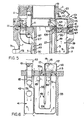
- An enclosure 113 is provided, at the location of each of the passages 75 in the inner wall 5, which extends over the area of an annular segment 35a that contains the entry ports of the downwardly extending hot legs 51 of the heat transfer tubes 49, the enclosure being open at the bottom thereof, and welded to the annular segment 35a.
- four such enclosures 113 are used which comprise side walls 115 and top 117, which top 117 may be provided with a removable cover 119.
- an opening 121 is provided through the wall communicating with the passage, and a seal member 123 is used to prevent leakage of primary coolant from the passage 75 to areas outside the enclosure 113.
- the hot primary coolant passing through passage 75 enters the enclosure 113 and is directed downwardly through the downwardly extending legs 51 of the heat transfer tubes 49, around the U-bend portion 53, and then upwardly through legs 55 and is discharged into the upper open annular space 23.
- the primary coolant is then directed by pump 63 back through the conduit 85 to the region 43 between inner wall 5 and outer surface 45 of primary coolant baffle 27.
- the reactor vessel 131 is formed from mating sections 3a and 3b and has the features described in the embodiment of Figures 5 and 6, except that the enclosure and placement thereof is distinct.
- the enclosure 133 which is open at the bottom, is formed from walls 135 and top 137, and is welded to a segment 35a.
- a removable cover 139 may be provided in the top wall 137.
- the enclosure is open at the bottom thereof and extends over the area of a tube sheet segment 35a that contains the exit ports of the upwardly extending cold legs 55 of the heat transfer tubes 49.
- a second enclosure 141 is provided about the circular opening 57 in the sealing plate 35 which encloses the impeller 59 and shaft 61 of the recirculating pump.
- an inlet port 145 is provided in a wall 143 of the second enclosure 141 which faces the enclosure 133.
- a discharge port 147 is provided in the wall 135 of the enclosure, facing the second enclosure 141.
- a flexible seal 149 connects the facing walls 135 and 143, about the discharge port 147 and inlet port 145.
- the second enclosure 141 thus serves to receive primary coolant from enclosures 133 positioned on opposite sides of the second enclosure 141.
- the hot primary coolant flows through passages 75 into the open annular space 23 and. flows downwardly through the downwardly extending legs 51 of the heat transfer tubes 49, around the U-bend portion 53 and upwardly through legs 55.
- the cooled primary coolant then is discharged from the cold legs 55 into enclosure 133.
- This cooled primary coolant is directed through discharge port 147, flexible seal 149, and inlet port 145 into the second enclosure 141.
- the pump 63 directs the primary coolant back through the conduit 85 to the region 43 between inner wall 5 and the outer surface 45 of primary coolant baffle 27.
- the welded seal 109 used to seal the radially extending edges of the tube sheet segments 35a and the peripheral edges thereof to the inner wall 5 and outer wall 7 of the section 3b of the pressure vessel is preferably of a J-shape as illustrated in Figure 11. This type of seal is usable since the springs 111 provide most of the force necessary to tightly seat the tube sheet segments 35a, and the welded seal serves primarily to seal the upper section 37 from the lower section 39 of the annular space 9.
- the pressurizer with an interconnecting surge line would be located outside the pressure vessel.
- the steam generator tube bundles are easily removed or replaced.
Landscapes
- Physics & Mathematics (AREA)
- Engineering & Computer Science (AREA)
- Plasma & Fusion (AREA)
- General Engineering & Computer Science (AREA)
- High Energy & Nuclear Physics (AREA)
- Chemical & Material Sciences (AREA)
- Chemical Kinetics & Catalysis (AREA)
- Heat-Exchange Devices With Radiators And Conduit Assemblies (AREA)
- Treatment Of Water By Oxidation Or Reduction (AREA)
Applications Claiming Priority (2)
| Application Number | Priority Date | Filing Date | Title |
|---|---|---|---|
| US60785584A | 1984-05-07 | 1984-05-07 | |
| US607855 | 1984-05-07 |
Publications (2)
| Publication Number | Publication Date |
|---|---|
| EP0164525A1 true EP0164525A1 (fr) | 1985-12-18 |
| EP0164525B1 EP0164525B1 (fr) | 1989-07-05 |
Family
ID=24434002
Family Applications (1)
| Application Number | Title | Priority Date | Filing Date |
|---|---|---|---|
| EP85104570A Expired EP0164525B1 (fr) | 1984-05-07 | 1985-04-16 | Réacteur nucléaire intégré de faibles dimensions, à eau pressurisée |
Country Status (6)
| Country | Link |
|---|---|
| EP (1) | EP0164525B1 (fr) |
| JP (1) | JPS60239694A (fr) |
| KR (1) | KR930004813B1 (fr) |
| DE (1) | DE3571358D1 (fr) |
| ES (1) | ES8707002A1 (fr) |
| IT (1) | IT1184550B (fr) |
Cited By (7)
| Publication number | Priority date | Publication date | Assignee | Title |
|---|---|---|---|---|
| EP0353867A1 (fr) * | 1988-07-21 | 1990-02-07 | Rolls-Royce And Associates Limited | Système passif de refroidissement de secours du coeur et évacuation de la chaleur résiduelle à pleine pression pour réacteurs nucléaires refroidis par l'eau |
| WO2001018820A2 (fr) * | 1999-09-08 | 2001-03-15 | Westinghouse Electric Company Llc | Chaudiere nucleaire assemblee, transportable, independante avec reserve a vie de combustible, et exploitation de cette chaudiere |
| US6813328B2 (en) * | 2002-12-13 | 2004-11-02 | Curtiss-Wright Electro-Mechanical Corporation | Nuclear reactor submerged high temperature spool pump |
| WO2012142021A1 (fr) | 2011-04-13 | 2012-10-18 | Babcock & Wilcox Nuclear Energy, Inc. | Réacteur nucléaire à eau sous pression intégré et compact |
| WO2013095741A2 (fr) | 2011-11-10 | 2013-06-27 | Babcock & Wilcox Nuclear Energy, Inc. | Réacteur à eau sous pression ayant un plénum supérieur comprenant un barrage de blocage d'écoulement croisé |
| US9394908B2 (en) | 2011-05-17 | 2016-07-19 | Bwxt Nuclear Energy, Inc. | Pressurized water reactor with upper vessel section providing both pressure and flow control |
| US20180322965A1 (en) * | 2011-10-26 | 2018-11-08 | Bwxt Mpower, Inc. | Pressurized water reactor with upper vessel section providing both pressure and flow control |
Families Citing this family (3)
| Publication number | Priority date | Publication date | Assignee | Title |
|---|---|---|---|---|
| JPS6446686A (en) * | 1987-08-17 | 1989-02-21 | Japan Atomic Energy Res Inst | Directly coupled pressurizer type reactor |
| US8681928B2 (en) * | 2011-05-16 | 2014-03-25 | Babcock & Wilcox Canada Ltd. | Pressurizer baffle plate and pressurized water reactor (PWR) employing same |
| RU2496161C1 (ru) * | 2012-08-08 | 2013-10-20 | Открытое Акционерное Общество "Ордена Ленина Научно-Исследовательский И Конструкторский Институт Энерготехники Имени Н.А. Доллежаля" | Интегральный водо-водяной ядерный реактор |
Citations (6)
| Publication number | Priority date | Publication date | Assignee | Title |
|---|---|---|---|---|
| US3255088A (en) * | 1960-08-22 | 1966-06-07 | Babcock & Wilcox Co | Integral nuclear reactor-steam generator unit |
| US3255089A (en) * | 1962-09-28 | 1966-06-07 | Babcock & Wilcox Ltd | Integral nuclear reactor-heat exchanger system |
| GB1049298A (en) * | 1964-11-10 | 1966-11-23 | Babcock & Wilcox Ltd | Improvements in nuclear reactors |
| US3322641A (en) * | 1964-06-29 | 1967-05-30 | Atomic Energy Authority Uk | Integrated nuclear reactor-steam generator |
| GB1074345A (en) * | 1963-07-19 | 1967-07-05 | Atomenergi Ab | Nuclear reactor assembly |
| FR1579240A (fr) * | 1967-08-13 | 1969-08-22 |
-
1985
- 1985-04-16 DE DE8585104570T patent/DE3571358D1/de not_active Expired
- 1985-04-16 EP EP85104570A patent/EP0164525B1/fr not_active Expired
- 1985-05-03 ES ES542812A patent/ES8707002A1/es not_active Expired
- 1985-05-06 IT IT20589/85A patent/IT1184550B/it active
- 1985-05-07 KR KR1019850003088A patent/KR930004813B1/ko active IP Right Grant
- 1985-05-07 JP JP60095700A patent/JPS60239694A/ja active Granted
Patent Citations (6)
| Publication number | Priority date | Publication date | Assignee | Title |
|---|---|---|---|---|
| US3255088A (en) * | 1960-08-22 | 1966-06-07 | Babcock & Wilcox Co | Integral nuclear reactor-steam generator unit |
| US3255089A (en) * | 1962-09-28 | 1966-06-07 | Babcock & Wilcox Ltd | Integral nuclear reactor-heat exchanger system |
| GB1074345A (en) * | 1963-07-19 | 1967-07-05 | Atomenergi Ab | Nuclear reactor assembly |
| US3322641A (en) * | 1964-06-29 | 1967-05-30 | Atomic Energy Authority Uk | Integrated nuclear reactor-steam generator |
| GB1049298A (en) * | 1964-11-10 | 1966-11-23 | Babcock & Wilcox Ltd | Improvements in nuclear reactors |
| FR1579240A (fr) * | 1967-08-13 | 1969-08-22 |
Cited By (19)
| Publication number | Priority date | Publication date | Assignee | Title |
|---|---|---|---|---|
| EP0353867A1 (fr) * | 1988-07-21 | 1990-02-07 | Rolls-Royce And Associates Limited | Système passif de refroidissement de secours du coeur et évacuation de la chaleur résiduelle à pleine pression pour réacteurs nucléaires refroidis par l'eau |
| WO1990001207A1 (fr) * | 1988-07-21 | 1990-02-08 | Imai, Shosuke | Systeme de refroidissement passif de secours pour reacteurs nucleaires refroidis par l'eau |
| US5102616A (en) * | 1988-07-21 | 1992-04-07 | Rolls-Royce And Associates Limited | Full pressure passive emergency core cooling and residual heat removal system for water cooled nuclear reactors |
| WO2001018820A2 (fr) * | 1999-09-08 | 2001-03-15 | Westinghouse Electric Company Llc | Chaudiere nucleaire assemblee, transportable, independante avec reserve a vie de combustible, et exploitation de cette chaudiere |
| WO2001018820A3 (fr) * | 1999-09-08 | 2001-10-04 | Westinghouse Electric Corp | Chaudiere nucleaire assemblee, transportable, independante avec reserve a vie de combustible, et exploitation de cette chaudiere |
| US6813328B2 (en) * | 2002-12-13 | 2004-11-02 | Curtiss-Wright Electro-Mechanical Corporation | Nuclear reactor submerged high temperature spool pump |
| EP2697797A1 (fr) * | 2011-04-13 | 2014-02-19 | Babcock & Wilcox Nuclear Energy, Inc. | Réacteur nucléaire à eau sous pression intégré et compact |
| WO2012142021A1 (fr) | 2011-04-13 | 2012-10-18 | Babcock & Wilcox Nuclear Energy, Inc. | Réacteur nucléaire à eau sous pression intégré et compact |
| EP2697797A4 (fr) * | 2011-04-13 | 2014-10-08 | Babcock & Wilcox Nuclear Energy Inc | Réacteur nucléaire à eau sous pression intégré et compact |
| US9812225B2 (en) | 2011-04-13 | 2017-11-07 | Bwxt Mpower, Inc. | Compact integral pressurized water nuclear reactor |
| US9394908B2 (en) | 2011-05-17 | 2016-07-19 | Bwxt Nuclear Energy, Inc. | Pressurized water reactor with upper vessel section providing both pressure and flow control |
| US10047749B2 (en) | 2011-05-17 | 2018-08-14 | Bwxt Mpower, Inc. | Pressurized water reactor with upper vessel section providing both pressure and flow control |
| US20180322965A1 (en) * | 2011-10-26 | 2018-11-08 | Bwxt Mpower, Inc. | Pressurized water reactor with upper vessel section providing both pressure and flow control |
| US10892061B2 (en) | 2011-10-26 | 2021-01-12 | Bwxt Mpower, Inc. | Pressurized water reactor with upper vessel section providing both pressure and flow control |
| US20220277862A1 (en) * | 2011-10-26 | 2022-09-01 | Bwxt Mpower, Inc. | Pressurized water reactor with upper vessel section providing both pressure and flow control |
| US11837370B2 (en) | 2011-10-26 | 2023-12-05 | Bwxt Mpower, Inc. | Pressurized water reactor with upper vessel section providing both pressure and flow control |
| WO2013095741A2 (fr) | 2011-11-10 | 2013-06-27 | Babcock & Wilcox Nuclear Energy, Inc. | Réacteur à eau sous pression ayant un plénum supérieur comprenant un barrage de blocage d'écoulement croisé |
| EP2777048A4 (fr) * | 2011-11-10 | 2015-05-20 | Babcock & Wilcox Nuclear Energy Inc | Réacteur à eau sous pression ayant un plénum supérieur comprenant un barrage de blocage d'écoulement croisé |
| US9558855B2 (en) | 2011-11-10 | 2017-01-31 | Bwxt Nuclear Energy, Inc. | Pressurized water reactor with upper plenum including cross-flow blocking weir |
Also Published As
| Publication number | Publication date |
|---|---|
| KR850008425A (ko) | 1985-12-16 |
| EP0164525B1 (fr) | 1989-07-05 |
| IT8520589A0 (it) | 1985-05-06 |
| JPS60239694A (ja) | 1985-11-28 |
| ES8707002A1 (es) | 1987-07-01 |
| JPH0232596B2 (fr) | 1990-07-20 |
| ES542812A0 (es) | 1987-07-01 |
| KR930004813B1 (ko) | 1993-06-08 |
| DE3571358D1 (en) | 1989-08-10 |
| IT1184550B (it) | 1987-10-28 |
Similar Documents
| Publication | Publication Date | Title |
|---|---|---|
| US3401082A (en) | Integral steam generator and nuclear reactor combination | |
| EP2571028B1 (fr) | Réflecteur de cuve de réacteur à écoulement intégré | |
| EP0164525B1 (fr) | Réacteur nucléaire intégré de faibles dimensions, à eau pressurisée | |
| US3255088A (en) | Integral nuclear reactor-steam generator unit | |
| US20190103195A1 (en) | Pool type liquid metal fast spectrum reactor using a printed circuit heat exchanger connection to the power conversion system | |
| US3290222A (en) | Compact nuclear steam generator | |
| US3245881A (en) | Integral boiler nuclear reactor | |
| US4407773A (en) | Nuclear reactor installation | |
| US3425907A (en) | Nuclear energy reactor plant having one or more heat exchangers | |
| US10249397B2 (en) | Modular reactor steam generator configured to cover a reactor outer wall circumference | |
| US3916841A (en) | Steam generator for a pressurized-water coolant nuclear reactor | |
| US4312184A (en) | Fluid circulation system for heat exchangers | |
| US3385760A (en) | Integral nuclear reactor-heat exchanger system | |
| JPS62165193A (ja) | 原子炉蒸気発生プラント | |
| US3915123A (en) | Steam generator | |
| US4138318A (en) | Nuclear reactor system of the fast type | |
| US4909981A (en) | Nuclear reactor | |
| US4173997A (en) | Modular steam generator | |
| US3442760A (en) | Integral nuclear reactor with coolant penetrations formed in a separable module of the reactor vessel | |
| FR2106620B1 (fr) | ||
| US4761261A (en) | Nuclear reactor | |
| GB1586480A (en) | Tube bundle assembly for a heat exchanger | |
| JPH04318206A (ja) | 蒸気タービン発電装置 | |
| CN85101411B (zh) | 小型整体式压水核反应堆 | |
| RU2776940C2 (ru) | Бассейновый жидкометаллический реактор на быстрых нейтронах, использующий соединение пластинчатого теплообменника с вытравленными каналами и системы преобразования мощности |
Legal Events
| Date | Code | Title | Description |
|---|---|---|---|
| PUAI | Public reference made under article 153(3) epc to a published international application that has entered the european phase |
Free format text: ORIGINAL CODE: 0009012 |
|
| AK | Designated contracting states |
Designated state(s): BE DE FR GB SE |
|
| 17P | Request for examination filed |
Effective date: 19860520 |
|
| 17Q | First examination report despatched |
Effective date: 19870911 |
|
| GRAA | (expected) grant |
Free format text: ORIGINAL CODE: 0009210 |
|
| AK | Designated contracting states |
Kind code of ref document: B1 Designated state(s): BE DE FR GB SE |
|
| REF | Corresponds to: |
Ref document number: 3571358 Country of ref document: DE Date of ref document: 19890810 |
|
| ET | Fr: translation filed | ||
| PLBE | No opposition filed within time limit |
Free format text: ORIGINAL CODE: 0009261 |
|
| STAA | Information on the status of an ep patent application or granted ep patent |
Free format text: STATUS: NO OPPOSITION FILED WITHIN TIME LIMIT |
|
| 26N | No opposition filed | ||
| PGFP | Annual fee paid to national office [announced via postgrant information from national office to epo] |
Ref country code: SE Payment date: 19910402 Year of fee payment: 7 Ref country code: GB Payment date: 19910402 Year of fee payment: 7 |
|
| PGFP | Annual fee paid to national office [announced via postgrant information from national office to epo] |
Ref country code: BE Payment date: 19910415 Year of fee payment: 7 |
|
| PGFP | Annual fee paid to national office [announced via postgrant information from national office to epo] |
Ref country code: FR Payment date: 19910419 Year of fee payment: 7 |
|
| PGFP | Annual fee paid to national office [announced via postgrant information from national office to epo] |
Ref country code: DE Payment date: 19910628 Year of fee payment: 7 |
|
| PG25 | Lapsed in a contracting state [announced via postgrant information from national office to epo] |
Ref country code: GB Effective date: 19920416 |
|
| PG25 | Lapsed in a contracting state [announced via postgrant information from national office to epo] |
Ref country code: SE Effective date: 19920417 |
|
| PG25 | Lapsed in a contracting state [announced via postgrant information from national office to epo] |
Ref country code: BE Effective date: 19920430 |
|
| BERE | Be: lapsed |
Owner name: WESTINGHOUSE ELECTRIC CORP. Effective date: 19920430 |
|
| GBPC | Gb: european patent ceased through non-payment of renewal fee | ||
| PG25 | Lapsed in a contracting state [announced via postgrant information from national office to epo] |
Ref country code: FR Effective date: 19921230 |
|
| PG25 | Lapsed in a contracting state [announced via postgrant information from national office to epo] |
Ref country code: DE Effective date: 19930101 |
|
| REG | Reference to a national code |
Ref country code: FR Ref legal event code: ST |
|
| EUG | Se: european patent has lapsed |
Ref document number: 85104570.8 Effective date: 19921108 |