EP0163903A1 - Schwärzungsgrad-Korrekturverfahren sowie Vorrichtung für Subtraktionsbilder - Google Patents
Schwärzungsgrad-Korrekturverfahren sowie Vorrichtung für Subtraktionsbilder Download PDFInfo
- Publication number
- EP0163903A1 EP0163903A1 EP85104941A EP85104941A EP0163903A1 EP 0163903 A1 EP0163903 A1 EP 0163903A1 EP 85104941 A EP85104941 A EP 85104941A EP 85104941 A EP85104941 A EP 85104941A EP 0163903 A1 EP0163903 A1 EP 0163903A1
- Authority
- EP
- European Patent Office
- Prior art keywords
- value
- signal
- difference signal
- maximum
- minimum
- Prior art date
- Legal status (The legal status is an assumption and is not a legal conclusion. Google has not performed a legal analysis and makes no representation as to the accuracy of the status listed.)
- Granted
Links
- 238000000034 method Methods 0.000 title claims description 53
- 230000005855 radiation Effects 0.000 claims abstract description 74
- OAICVXFJPJFONN-UHFFFAOYSA-N Phosphorus Chemical compound [P] OAICVXFJPJFONN-UHFFFAOYSA-N 0.000 claims abstract description 51
- 238000006243 chemical reaction Methods 0.000 claims abstract description 29
- 230000004936 stimulating effect Effects 0.000 claims description 7
- 206010073306 Exposure to radiation Diseases 0.000 claims description 6
- 238000010586 diagram Methods 0.000 description 5
- 238000003672 processing method Methods 0.000 description 5
- 238000009826 distribution Methods 0.000 description 3
- 230000035945 sensitivity Effects 0.000 description 3
- 229940039231 contrast media Drugs 0.000 description 2
- 239000002872 contrast media Substances 0.000 description 2
- 230000000694 effects Effects 0.000 description 2
- 238000002347 injection Methods 0.000 description 2
- 239000007924 injection Substances 0.000 description 2
- 238000010521 absorption reaction Methods 0.000 description 1
- NIXOWILDQLNWCW-UHFFFAOYSA-N acrylic acid group Chemical group C(C=C)(=O)O NIXOWILDQLNWCW-UHFFFAOYSA-N 0.000 description 1
- 230000002411 adverse Effects 0.000 description 1
- 238000003745 diagnosis Methods 0.000 description 1
- 230000001747 exhibiting effect Effects 0.000 description 1
- 239000000463 material Substances 0.000 description 1
- 238000002601 radiography Methods 0.000 description 1
- 230000002123 temporal effect Effects 0.000 description 1
- 230000004304 visual acuity Effects 0.000 description 1
Images


Classifications
-
- G—PHYSICS
- G06—COMPUTING; CALCULATING OR COUNTING
- G06T—IMAGE DATA PROCESSING OR GENERATION, IN GENERAL
- G06T5/00—Image enhancement or restoration
- G06T5/50—Image enhancement or restoration using two or more images, e.g. averaging or subtraction
-
- G—PHYSICS
- G01—MEASURING; TESTING
- G01T—MEASUREMENT OF NUCLEAR OR X-RADIATION
- G01T1/00—Measuring X-radiation, gamma radiation, corpuscular radiation, or cosmic radiation
- G01T1/16—Measuring radiation intensity
- G01T1/20—Measuring radiation intensity with scintillation detectors
- G01T1/2012—Measuring radiation intensity with scintillation detectors using stimulable phosphors, e.g. stimulable phosphor sheets
- G01T1/2014—Reading out of stimulable sheets, e.g. latent image
-
- H—ELECTRICITY
- H04—ELECTRIC COMMUNICATION TECHNIQUE
- H04N—PICTORIAL COMMUNICATION, e.g. TELEVISION
- H04N1/00—Scanning, transmission or reproduction of documents or the like, e.g. facsimile transmission; Details thereof
- H04N1/40—Picture signal circuits
- H04N1/407—Control or modification of tonal gradation or of extreme levels, e.g. background level
- H04N1/4072—Control or modification of tonal gradation or of extreme levels, e.g. background level dependent on the contents of the original
- H04N1/4074—Control or modification of tonal gradation or of extreme levels, e.g. background level dependent on the contents of the original using histograms
Definitions
- This invention relates to a method of correcting the density of a subtraction image obtained by a subtraction processing of radiation images, and an apparatus for carrying out the method.
- This invention particularly relates to a method of correcting the density of a subtraction image obtained by a digital subtraction processing of radiation images conducted by use of stimulable phosphor sheets so that the density range of the subtraction image becomes always the same, and an apparatus for carrying out the method.
- a digital subtraction processing method is used for processing radiation images.
- two radiation images recorded under conditions different from each other are photoelectrically read out to obtain digital image signals, which are then subjected to a subtraction processing with respect to the corresponding picture elements of the images, thereby to obtain a difference signal for forming an image of a specific structure contained in the radiation images.
- the method makes it possible to reproduce a radiation image of only the specific structure by use of the signal thus obtained.
- subtraction processing is classified into the so-called temporal (time difference) subtraction processing method and the so-called energy subtraction processing method.
- the image of a specific structure is extracted by subtracting the image signal of a radiation image obtained without injection of contrast media from the image signal of a radiation image in which the image of the specific structure is enhanced by the injection of contrast media.
- an object is exposed to radiations having energy distributions different from each other to obtain two radiation images respectively containing the images of a specific structure recorded on the basis of the intrinsic radiation energy absorption characteristics of the specific structure. Then, the image signals of the two radiation images are weighted appropriately when necessary, and subjected to subtraction to extract the image of the specific structure.
- DR digital radiography
- a novel digital subtraction processing method has been proposed, for example, in Japanese Unexamined Patent Publication No. 58(1983)-163340.
- the method comprises the steps of (i) using two or more stimulable phosphor sheets exhibiting an extremely wide latitude of exposure to a radiation, (ii) exposing the stimulable phosphor sheets to the radiation passing through the same object under different conditions to have radiation images of the object stored in the stimulable phosphor sheets, image information on the specific structure being different between the radiation images, (iii) detecting the radiation images by scanning with stimulating rays to obtain digital image signals, and (iv) conducting a digital subtraction processing by use of the digital image signals.
- the stimulable phosphor sheets comprise a stimulable phosphor which is able to store a part of the radiation energy when exposed to a radiation such as X-rays, ⁇ -rays, ⁇ -rays, o-rays, cathode rays or ultraviolet rays, and then emits light in proportion to the stored energy of the radiation when exposed to stimulating rays such as visible light, as disclosed for example in U.S. Patent No. 4,258,264.
- the stimulable phosphor sheets exhibit an extremely wide latitude of exposure and a markedly high resolving power.
- the digital subtraction processing is conducted by use of the radiation images stored in the stimulable phosphor sheets, it is possible to obtain a radiation image having an improved image quality, particularly a high diagnostic efficiency and accuracy, regardless of the amount of radiation to which the stimulable phosphor sheets are exposed.
- the stimulable phosphor sheets can also be used for the aforesaid energy subtraction processing.
- the density range (or luminance range when the images are reproduced on a cathode ray tube) becomes different among the reproduced images. This is because image signals detected from two or more radiation images for the subtraction processing are caused to fluctuate by any fluctuation in sensitivity of the stimulable phosphor sheets, fluctuation in sensitivity of the image read-out apparatus, fluctuation in radiation exposure dose at the radiation image recording step, or the like.
- the difference signal obtained by the subtraction processing is very weak.
- the level of the fluctuation component in the difference signal obtained from the image signals becomes markedly higher than the level of the corrrect signal component, and the density range of the subtraction image reproduced by use of the difference signal fluctuates largely.
- the subtraction image often becomes unsuitable for viewing, particularly for diagnostic purposes, so that it is not always possible to carry out correct diagnosis, for example, by comparing many subtraction images.
- radiation energy to which the stimulable phosphor sheets are exposed may be changed by changing the tube voltage of the radiation source.
- a filter for changing the energy distribution of the radiation may be inserted between the radiation source and the object, or any other known method may be used.
- the radiation images may be recorded by a single radiation exposure operation by use of a stimulable phosphor sheet-filter stack or the like as described in Japanese Patent Application No. 57(1982)-193765.
- the primary object of the present invention is to provide a method of correcting the density of an energy subtraction image so that energy subtraction images having the same density range and an improved image quality, particularly a high diagnostic efficiency and accuracy, are obtained.
- Another object of the present invention is to provide a method of correcting the density of an energy subtraction image so that energy subtraction images having the same density range, the same contrast, and an improved image quality, particularly a high diagnostic efficiency and accuracy, are obtained.
- the specific object of the present invention is to provide an apparatus for carrying out the method.
- the present invention provides a method of correcting the density of a subtraction image in a gradation processing in an energy subtraction processing which includes the steps of exposing two or more stimulable phosphor sheets to radiations having different levels of energy passing through the same object to have radiation images of said object stored in said stimulable phosphor sheets, at least a part of the image information being different between said radiation images, scanning the respective stimulable phosphor sheets by stimulating rays to sequentially release the radiation energy stored in said stimulable phosphor sheets as light emission, photoelectrically detecting and converting the amounts of the emitted light into digital image signals, obtaining a difference signal for forming an image of a specific structure of said object by carrying out a subtraction processing of said digital image signals between corresponding picture elements of said radiation images, and then subjecting said difference signal to a gradation processing,
- the method of correcting the density of a subtraction image comprising the steps of: calculating a characteristic value in said difference signal, and making said characteristic value correspond to a predetermined density of a reproduced image.
- the characteristic value may be a mean value between the maximum value and the minimum value of the difference signal, the maximum frequency point signal calculated from a histogram of the difference signal (in many cases, the maximum frequency point signal represents the density of a predetermined image portion such as the background), or a mean value calculated from the histogram of the difference signal.
- the characteristic value it is also possible to use at least two different signal values calculated from the histogram of the difference signal, or to use the maximum signal value and the minimum signal value of the difference signal which may be calculated from the histogram of the difference signal or may be calculated by sequentially comparing the values of the difference signal.
- the method wherein the maximum signal value and the minimum signal value of the difference signal are calculated by sequentially comparing the values of the difference signal is advantageous over the method wherein they are calculated from the histogram in that the method can be achieved simply only with hardware and the operation speed is high.
- the difference signal may be uniformly converted prior to the gradation processing, or the gradation conversion table may be corrected.
- the apparatus for carrying out the method of correcting the density of a subtraction image in accordance with the present invention wherein the difference signal is uniformly converted prior to the gradation processing comprises:
- the apparatus for carrying out the method of correcting the density of a subtraction image in accordance with the present invention wherein the gradation conversion table is corrected comprises, instead of the signal correcting circuit in the aforesaid apparatus, a gradation conversion table correcting circuit for correcting the gradation conversion table so that the characteristic value of the difference signal corresponds to the predetermined density of the reproduced image.
- the general density or both the general density and the general contrast of energy subtraction images can be maintained the same among different the subtraction images. Therefore, it is possible to obtain subtraction images having markedly improved image quality, particularly a high diagnostic efficiency and accuracy. Further, since the density or both the density and the contrast are maintained within predetermined ranges, it becomes possible to very efficiently utilize the dynamic range of the recording medium on which the subtraction image is reproduced. Also, since the method of the present invention can be carried out automatically by use of electric circuits, the method is advantageous particularly when the subtraction operation processing is conducted continuously and the subtraction images are observed in real time mode by use of a cathode ray tube.
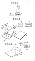
- Figure 1 shows the step of exposing stimulable phosphor sheets A and B respectively to X-rays 2 of different passing throuth the same object 1 levels of X-ray energy.
- the stimulable phosphor sheet A is exposed to X-rays 2 passing through the object 1 to have an X-ray image of the object 1 stored therein.
- the stimulable phosphor sheet A is quickly removed from the image recording position, and the stimulable phosphor sheet B is quickly moved to the image recording position.
- the tube voltage of an X-ray source 3 is changed, and an X-ray image of the object 1 is stored in the stimulable phosphor sheet B by the X-rays 2 having a different energy level.
- the relationship between the positions of the stimulable phosphor sheet A and the object 1 and the relationship between the stimulable phosphor sheet B and the object 1 are maintained the same.
- two radiation images differing from each other in at least a part of their image information are stored in the stimulable phosphor sheets A and B.
- the X-ray images are read out by use of the image read-out means as shown in Figure 2 to obtain digital image signals representing the X-ray images.
- a laser beam 11 emitted by a laser beam source 10 is deflected in the direction as indicated by the arrow X by a scanning mirror 12 to conduct main scanning.
- the stimulable phosphor sheet A is caused to release the X-ray energy stored therein as light 13 in proportion to the X-ray energy.
- the emitted light 13 enters a light guide member 14, which is made by forming a transparent acrylic sheet, from one end face thereof.
- the light guide member 14 may be of a shape and a material as disclosed in U.S. Patent No. 4,346,295.
- the light 13 is then guided through total reflection inside of the light guide member 14 up to a photomultiplier 15, and the amount of the light 13 is output as an image signal S by the photomultiplier 15.
- the image signal S is then converted into a digital image signal logSA of a logarithmic value (logS) by a log- converter 16 comprising an amplifier and an A/D converter.
- the digital image signal logSA is stored in a storage medium 17 such as a magnetic tape. Thereafter, the X-ray image stored in the other stimulable phosphor sheet B is read out therefrom in exactly the same manner as described above, and digital image signal logSB thus obtained is stored in the storage medium 17.
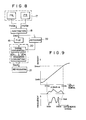
- FIG. 3 shows the flow of the subtraction processing wherein an embodiment of the method of correcting the density of a subtraction image in accordance with the present invention is employed.
- the digital image signals logSA and logSB are read respectively from image files 17A and 17B in the storage medium 17, and are sent to a subtraction operation circuit 18.
- the subtraction operation circuit 18 weights the digital image signals logSA and logSB obtained as described above by use of weight factors a and b, and conducts a subtraction processing between the digital image signals logSA and logSB with respect to the corresponding picture elements to obtain a digital difference signal Ssub as expressed by where a, b and c are constants.
- the constant c is a bias component for adjusting the density of the difference signal Ssub approximately to a predetermined value.
- the difference signal Ssub is stored in an image file 19 and is then sent to an image processing circuit 20 in which a gradation processing is carried out on the basis of a gradation conversion table 20c via a histogram operation circuit 20a and a signal correcting circuit 20b as described later.
- a difference signal Ssub' obtained by the gradation processing is sent to an image reproducing apparatus 21, for example, a display device such as a cathode ray tube or a point-by-point scanning apparatus which reproduces a subtraction image by use of the difference signal Ssub'.
- Figure 4 shows an apparatus for reproducing the image by point-by-point scanning as an example of the subtraction image reproducing system.
- a photosensitive film 30 is moved in the sub-scanning direction as indicated by the arrow Y, and at the same time a laser beam 31 is deflected onto the photosensitive film 30 in the main scanning direction as indicated by the arrow X.
- the laser beam 31 is modulated by an A/O modulator 32 with an image signal sent from an image signal feeder 33, thereby to form a visible image on the photosensitive film 30.
- an A/O modulator 32 with an image signal sent from an image signal feeder 33, thereby to form a visible image on the photosensitive film 30.
- the difference signal Ssub' as the modulating image signal, it is possible to reproduce a visible image wherein only a desired specific structure is extracted by the digital subtraction processing on the photosensitive film 30.
- the difference signal Ssub is sent to a histogram operation circuit 20a for obtaining a histogram of the difference signal Ssub.
- the histogram operation circuit 20a calculates the mean value (Smax + Smin)/2 between the maximum value Smax and the minimum value Smin of the histogram.
- the difference signal Ssub is uniformly converted by a signal correcting circuit 20b so that the mean value corresponds to a predetermined value Sc as indicated by the broken line in Figure 5. Accordingly, the subtraction image portion represented by the mean value always has a predetermined density Dc corresponding to the predetermined value Sc, and the general density of the subtraction images becomes always the same.
- FIG 6 shows the flow of the subtraction processing in which another embodiment of the method in accordance with the present invention is employed.
- the mean value calculated as described above is sent from the histogram operation circuit 20a to a gradation conversion table correcting circuit 20d which corrrects (i.e. shifts) the gradation conversion table 20c as shown in Figure 7 so that the mean vlaue corresponds to a predetermined value Sc.
- the subtraction image portion represented by the mean value always has a predetermined density Dc corresponding to the predetermined value Sc, and the general density of the subtraction images becomes always the same.
- the characteristic value of the difference signal Ssub it is possible to use any other value respresenting the characteristics of the difference signal, such as the maximum frequency point value or the average value of the difference signal histogram. Further, the characteristic value may be calculated from the whole difference signal or only from the difference signal of a pertinent region of the energy subtraction image where the density range should be maintained the same among the subtraction images. In the latter case, it is possible to select a plurality of pertinent regions, and to calculate the characteristic value from the difference signal at all of the pertinent regions or to calculate partial characteristic values of the respective pertinent regions and calculate a predetermined characteristic value, for example, the maximum value, the minimum value, the average value or the like, from the partial characteristic values.
- a predetermined characteristic value for example, the maximum value, the minimum value, the average value or the like
- FIG 8 shows the flow of a subtraction processing in which a further embodiment of the method in accordance with the present invention is employed.
- the difference signal Ssub obtained in the same manner as described with reference to Figure 3 is sent to a histogram operation circuit 22 for obtaining a histogram of the difference signal Ssub.
- the histogram operation circuit 22 calculates, for example, the maximum value Smax and the minimum value Smin of the difference signal Ssub from the histogram, and sends signals representing the maximum value Smax and the minimum value Smin to a signal converting circuit 20e of an image processing circuit 20.
- the signal converting circuit 20e converts the difference signal Ssub as expressed, for example, by so that the maximum value Smax and the minimum value Smin correspond respectively to predetermined values Cmax and Cmin.
- the signal p.Ssub+q obtained by the signal conversion is subjected to a gradation processing based on a gradation conversion table 20c in the image processing circuit 20.
- the predetermined values Cmax and Cmin correspond respectively to the maximum density value Dmax and the minimum density value Dmin of the subtraction image. Therefore, the subtraction image formed by the converted signal p.Ssub+q always has a predetermined density range and contrast.
- Figure 12 shows the flow of a subtraction processing in which a still further embodiment of the method in accordance with the present invention is employed.
- sequential comparison operation circuits 122a and 122b are used as the mears for calculating the maximum value and the minimum value.
- the sequential comparison operation circuit 122a stores the first value of the difference signal Ssub sent from the subtraction operation circuit 18 a3 the maximum value, and compares the stored value with the next sent value of the difference signal Ssub.
- the circuit 122a stores the larger value as the maximum value, and sequentially conducts the same processing on the subsequently sent values of the difference signal Ssub. By sequentially carrying out the processing up to the last value of the difference signal Ssub, the true maximum value Smax' over the whole range of the difference signal Ssub is obtained.
- the other sequential comparison operation circuit 122b compares the values of the difference signal Ssub in the same manner, and stores the smaller value as the minimum value of the difference signal Ssub, thereby calculating the true minimum value Smin' over the whole range of the difference signal Ssub.
- the maximum value Smax' and the minimum value Smin' of the difference signal Ssub are calculated by the sequential comparison method, instead of temporarily storing the first sent value of the difference signal Ssub as the maximum value Smax' or the minimum value Smin', it is also possible to store in advance an arbitrary signal value sufficiently smaller than the estimated maximum value Smax' as the maximum value and to store in advance an arbitrary signal value sufficiently larger than the estimated minimum value Smin' as the minimum value.
- the true maximum value Smax' and the true minimum value Smin' obtained as described above are respectively sent to a subtraction circuit 121a and an addition circuit 121b.
- a predetermined signal level S ⁇ a is subtracted from the true maximum value Smax', and the value (Smax'-SAa) is generated as the maximum value Smax for optimizing the gradation processing.
- a predetermined signal level SAb is added to the true minimum value Smin', and the value (Smin'+SAb) is generated as the minimum value Smin for optimizing the gradation processing.
- the gradation conversion table correcting circuit 120 receives the maximum value Smax and the minimum value Smin, and corrects the gradation conversion table 20c as indicated by the broken line in Figure 13 so that the maximum value Smax and the minimum value Smin respectively correspond to the maximum density value Dmax and the minimum density value Dmin of the subtraction image. By correcting the gradation conversion table 20c in this manner, the density range and the contrast of the subtraction image are maintained the same.
- noise components caused by signal noise and scattered radiation at the image recording step are contained in the difference signal Ssub on the maximum and minimum level sides.
- the signal level S ⁇ a subtracted from the true maximum value Smax' and the signal level S ⁇ b added to the true minimum value Smin' are adjusted to values corresponding to the noise components. Therefore, by using the values (Smax'-Sda) and (Smin'+S ⁇ b) as the maximum value Smax and the minimum value Smin for optimizing the gradation processing, it is possible to eliminate adverse effects of the signal noise and scattered radiation and to utilize more efficiently the dynamic range of the recording medium for the subtraction image.
- the present invention is applicable also to the case where a subtraction image is obtained by recording radiation images on three stimulable phosphor sheets by use of radiations having different levels of energy, and conducting a subtraction processing of image signals detected from the stimulable phosphor sheets, for example, as expressed by a x logSA + b x logSB - c x logSC + d where a, b and c denote weight factors and d denotes a bias component for adjusting the density of the difference signal approximately to a predetermined value.
- radiation energy to which the stimulable phosphor sheets are exposed may be changed by changing the tube voltage of the radiation source as in the aforesaid embodiments.
- a filter for changing the energy distribution of the radiation may be inserted between the radiation source and the object, or any other known method may be used.
- the radiation images may be recorded by a single radiation exposure operation by use of a stimulable phosphor sheet-filter stack or the like as described in Japanese Patent Application No. 57(1982)-193765.
Landscapes
- Physics & Mathematics (AREA)
- General Physics & Mathematics (AREA)
- Engineering & Computer Science (AREA)
- Theoretical Computer Science (AREA)
- Health & Medical Sciences (AREA)
- Life Sciences & Earth Sciences (AREA)
- High Energy & Nuclear Physics (AREA)
- Molecular Biology (AREA)
- Spectroscopy & Molecular Physics (AREA)
- Multimedia (AREA)
- Signal Processing (AREA)
- Radiography Using Non-Light Waves (AREA)
- Image Processing (AREA)
- Apparatus For Radiation Diagnosis (AREA)
Applications Claiming Priority (6)
| Application Number | Priority Date | Filing Date | Title |
|---|---|---|---|
| JP59081541A JPS60224386A (ja) | 1984-04-23 | 1984-04-23 | サブトラクシヨン画像の濃度補正方法および装置 |
| JP81541/84 | 1984-04-23 | ||
| JP59107912A JPS60251475A (ja) | 1984-05-28 | 1984-05-28 | サブトラクシヨン画像の階調処理最適化方法および装置 |
| JP59107911A JPS60250792A (ja) | 1984-05-28 | 1984-05-28 | サブトラクシヨン画像の階調処理最適化方法および装置 |
| JP107911/84 | 1984-05-28 | ||
| JP107912/84 | 1984-05-28 |
Publications (2)
| Publication Number | Publication Date |
|---|---|
| EP0163903A1 true EP0163903A1 (de) | 1985-12-11 |
| EP0163903B1 EP0163903B1 (de) | 1991-06-05 |
Family
ID=27303617
Family Applications (1)
| Application Number | Title | Priority Date | Filing Date |
|---|---|---|---|
| EP85104941A Expired EP0163903B1 (de) | 1984-04-23 | 1985-04-23 | Schwärzungsgrad-Korrekturverfahren sowie Vorrichtung für Subtraktionsbilder |
Country Status (3)
| Country | Link |
|---|---|
| US (1) | US5028781A (de) |
| EP (1) | EP0163903B1 (de) |
| DE (1) | DE3583065D1 (de) |
Cited By (6)
| Publication number | Priority date | Publication date | Assignee | Title |
|---|---|---|---|---|
| EP0258673A2 (de) * | 1986-09-02 | 1988-03-09 | Fuji Photo Film Co., Ltd. | Verfahren und Vorrichtung zur Verarbeitung eines Bildes gemäss eines Korrekturniveaus |
| EP0258740A2 (de) * | 1986-09-02 | 1988-03-09 | Fuji Photo Film Co., Ltd. | Verfahren und Vorrichtung zur Bildverarbeitung mit Gradationskorrektur des Bildsignals |
| EP0310021A2 (de) * | 1987-09-28 | 1989-04-05 | Dainippon Screen Mfg. Co., Ltd. | Gradationsumsetzungsschaltung unter Benutzung einer Nachschlagetabelle |
| EP0352491A1 (de) * | 1988-06-30 | 1990-01-31 | Dainippon Screen Mfg. Co., Ltd. | Verfahren zur Erzeugung einer Abstufungskorrekturkurve zur Korrektur des Abstufungscharakters eines Bildes |
| EP0360401A2 (de) * | 1988-09-22 | 1990-03-28 | International Business Machines Corporation | Verfahren und Vorrichtung zur Grauwertübersetzung in einem digitalen Datenaufzeichnungsgerät |
| EP0442468A1 (de) * | 1990-02-14 | 1991-08-21 | Fuji Photo Film Co., Ltd. | Verfahren zur Bildung von Energiesubtraktionsbildern |
Families Citing this family (3)
| Publication number | Priority date | Publication date | Assignee | Title |
|---|---|---|---|---|
| US5757022A (en) * | 1995-10-19 | 1998-05-26 | Fuji Photo Film Co., Ltd. | Image processing apparatus |
| US7136191B2 (en) * | 2002-06-24 | 2006-11-14 | Eastman Kodak Company | Method for inspecting prints |
| JP4416823B2 (ja) * | 2008-01-09 | 2010-02-17 | キヤノン株式会社 | 画像処理装置、画像処理方法、及びコンピュータプログラム |
Citations (3)
| Publication number | Priority date | Publication date | Assignee | Title |
|---|---|---|---|---|
| US4340911A (en) * | 1979-02-28 | 1982-07-20 | Fuji Photo Film Co., Ltd. | Image gradation processing method and apparatus for mammogram copying system |
| US4346406A (en) * | 1979-07-11 | 1982-08-24 | Fuji Photo Film Co., Ltd. | Gradation processing method for a radiation image recording system |
| EP0089665A1 (de) * | 1982-03-20 | 1983-09-28 | Fuji Photo Film Co., Ltd. | System und Anordnung zum Subtrahieren von Röntgenbildern |
Family Cites Families (4)
| Publication number | Priority date | Publication date | Assignee | Title |
|---|---|---|---|---|
| JPS5512429A (en) * | 1978-07-12 | 1980-01-29 | Fuji Photo Film Co Ltd | Radioactive image reader |
| JPS55116339A (en) * | 1979-02-28 | 1980-09-06 | Fuji Photo Film Co Ltd | Method and device for processing gradation of radiation picture of chest |
| EP0032521B1 (de) * | 1979-07-11 | 1984-05-30 | Fuji Photo Film Co., Ltd. | Verstärkungseinstellung für ein Bestrahlungsbild-Wiedergabesystem |
| JPS5932440A (ja) * | 1982-08-17 | 1984-02-21 | 富士写真フイルム株式会社 | 放射線画像のサブトラクシヨン処理方法 |
-
1985
- 1985-04-23 EP EP85104941A patent/EP0163903B1/de not_active Expired
- 1985-04-23 DE DE8585104941T patent/DE3583065D1/de not_active Expired - Fee Related
-
1987
- 1987-11-03 US US07/116,196 patent/US5028781A/en not_active Expired - Lifetime
Patent Citations (3)
| Publication number | Priority date | Publication date | Assignee | Title |
|---|---|---|---|---|
| US4340911A (en) * | 1979-02-28 | 1982-07-20 | Fuji Photo Film Co., Ltd. | Image gradation processing method and apparatus for mammogram copying system |
| US4346406A (en) * | 1979-07-11 | 1982-08-24 | Fuji Photo Film Co., Ltd. | Gradation processing method for a radiation image recording system |
| EP0089665A1 (de) * | 1982-03-20 | 1983-09-28 | Fuji Photo Film Co., Ltd. | System und Anordnung zum Subtrahieren von Röntgenbildern |
Cited By (16)
| Publication number | Priority date | Publication date | Assignee | Title |
|---|---|---|---|---|
| EP0258740A2 (de) * | 1986-09-02 | 1988-03-09 | Fuji Photo Film Co., Ltd. | Verfahren und Vorrichtung zur Bildverarbeitung mit Gradationskorrektur des Bildsignals |
| EP0258740A3 (en) * | 1986-09-02 | 1989-10-11 | Fuji Photo Film Co., Ltd. | Method of and apparatus for processing an image with gradation correction of video signal |
| EP0258673A3 (en) * | 1986-09-02 | 1990-01-17 | Fuji Photo Film Co., Ltd. | Method of and apparatus for processing an image according to a correction level |
| EP0258673A2 (de) * | 1986-09-02 | 1988-03-09 | Fuji Photo Film Co., Ltd. | Verfahren und Vorrichtung zur Verarbeitung eines Bildes gemäss eines Korrekturniveaus |
| EP0310021A2 (de) * | 1987-09-28 | 1989-04-05 | Dainippon Screen Mfg. Co., Ltd. | Gradationsumsetzungsschaltung unter Benutzung einer Nachschlagetabelle |
| EP0310021A3 (de) * | 1987-09-28 | 1991-07-31 | Dainippon Screen Mfg. Co., Ltd. | Gradationsumsetzungsschaltung unter Benutzung einer Nachschlagetabelle |
| US5123059A (en) * | 1987-09-28 | 1992-06-16 | Dainippon Screen Mfg. Co., Ltd. | Gradation converting circuit employing lookup table |
| US5155478A (en) * | 1988-04-22 | 1992-10-13 | International Business Machines Corporation | Method and apparatus for converting gray scale |
| EP0352491A1 (de) * | 1988-06-30 | 1990-01-31 | Dainippon Screen Mfg. Co., Ltd. | Verfahren zur Erzeugung einer Abstufungskorrekturkurve zur Korrektur des Abstufungscharakters eines Bildes |
| EP0360401A2 (de) * | 1988-09-22 | 1990-03-28 | International Business Machines Corporation | Verfahren und Vorrichtung zur Grauwertübersetzung in einem digitalen Datenaufzeichnungsgerät |
| EP0360401A3 (de) * | 1988-09-22 | 1991-10-23 | International Business Machines Corporation | Verfahren und Vorrichtung zur Grauwertübersetzung in einem digitalen Datenaufzeichnungsgerät |
| EP0442468A1 (de) * | 1990-02-14 | 1991-08-21 | Fuji Photo Film Co., Ltd. | Verfahren zur Bildung von Energiesubtraktionsbildern |
| EP0689794A2 (de) * | 1990-02-14 | 1996-01-03 | Fuji Photo Film Co., Ltd. | Formationsverfahren von Energie-Subtraktionsbildern, Verfahren und Gerät zur Glättung von Bildern |
| US5485371A (en) * | 1990-02-14 | 1996-01-16 | Fuji Photo Film Co., Ltd. | Method for forming energy subtraction radiation images, and method and apparatus for smoothing radiation images |
| EP0689795A3 (de) * | 1990-02-14 | 1996-04-03 | Fuji Photo Film Co Ltd | Verfahren und Gerät zur Glättung von Bildern |
| EP0689794A3 (de) * | 1990-02-14 | 1996-04-24 | Fuji Photo Film Co Ltd | Formationsverfahren von Energie-Subtraktionsbildern, Verfahren und Gerät zur Glättung von Bildern |
Also Published As
| Publication number | Publication date |
|---|---|
| EP0163903B1 (de) | 1991-06-05 |
| DE3583065D1 (de) | 1991-07-11 |
| US5028781A (en) | 1991-07-02 |
Similar Documents
| Publication | Publication Date | Title |
|---|---|---|
| CA1223980A (en) | Method of adjusting radiation image read-out apparatus | |
| US5048110A (en) | Method and apparatus for automatically correcting subtraction image density | |
| EP0162321A1 (de) | Hochgeschwindigkeitsabbildungsaufzeichnungsvorrichtung für Energie-Subtraktionsverarbeitung | |
| US4761739A (en) | Density correcting method and apparatus for energy substraction image | |
| US4816681A (en) | Method and apparatus for improving quality of energy subtraction image | |
| US4950894A (en) | Radiation image read-out method | |
| US5067163A (en) | Method for determining a desired image signal range from an image having a single background | |
| US4999497A (en) | Radiation image read-out and reproducing method and apparatus | |
| US5028781A (en) | Density correcting method and apparatus for subtraction image | |
| US5049748A (en) | Method and apparatus for forming energy subtraction images | |
| US5060081A (en) | Method of adjusting read-out condition and/or image processing condition for radiation image | |
| US4755672A (en) | Radiation image reproducing method and apparatus | |
| US5179597A (en) | Method for determining an image point in an object image | |
| US4952807A (en) | Method of adjusting radiation image read-out conditions and image processing conditions | |
| US4914295A (en) | Radiation image read-out and image signal storing apparatus | |
| US4870277A (en) | Radiation image read-out method and apparatus, and radiation image read-out and reproducing method and apparatus | |
| US5029083A (en) | Energy subtraction processing method using weighted average of plural stacked sheets for creating high energy image | |
| EP0154880B1 (de) | Verfahren zur Einstellung der Bedingungen beim Auslesen eines Strahlungsbildes und/oder der Bildverarbeitungsbedingungen | |
| EP0189206B1 (de) | Verfahren zur Anpassung des Auswertens eines Strahlungsbildes | |
| US4899049A (en) | Radiation image read-out apparatus | |
| US4695726A (en) | Radiation image reproducing method and apparatus | |
| EP0254301B1 (de) | Verfahren zur Bedingungseinstellung von Strahlungsbildverarbeitung | |
| US4629900A (en) | Radiation image read-out method | |
| JPS6255641A (ja) | 放射線画像情報読取方法 | |
| JPS60250792A (ja) | サブトラクシヨン画像の階調処理最適化方法および装置 |
Legal Events
| Date | Code | Title | Description |
|---|---|---|---|
| PUAI | Public reference made under article 153(3) epc to a published international application that has entered the european phase |
Free format text: ORIGINAL CODE: 0009012 |
|
| AK | Designated contracting states |
Designated state(s): DE FR NL |
|
| 17P | Request for examination filed |
Effective date: 19860204 |
|
| 17Q | First examination report despatched |
Effective date: 19870720 |
|
| GRAA | (expected) grant |
Free format text: ORIGINAL CODE: 0009210 |
|
| AK | Designated contracting states |
Kind code of ref document: B1 Designated state(s): DE FR NL |
|
| REF | Corresponds to: |
Ref document number: 3583065 Country of ref document: DE Date of ref document: 19910711 |
|
| ET | Fr: translation filed | ||
| PLBE | No opposition filed within time limit |
Free format text: ORIGINAL CODE: 0009261 |
|
| STAA | Information on the status of an ep patent application or granted ep patent |
Free format text: STATUS: NO OPPOSITION FILED WITHIN TIME LIMIT |
|
| 26N | No opposition filed | ||
| PGFP | Annual fee paid to national office [announced via postgrant information from national office to epo] |
Ref country code: FR Payment date: 20020405 Year of fee payment: 18 |
|
| PGFP | Annual fee paid to national office [announced via postgrant information from national office to epo] |
Ref country code: NL Payment date: 20020425 Year of fee payment: 18 |
|
| PGFP | Annual fee paid to national office [announced via postgrant information from national office to epo] |
Ref country code: DE Payment date: 20020531 Year of fee payment: 18 |
|
| PG25 | Lapsed in a contracting state [announced via postgrant information from national office to epo] |
Ref country code: NL Free format text: LAPSE BECAUSE OF NON-PAYMENT OF DUE FEES Effective date: 20031101 Ref country code: DE Free format text: LAPSE BECAUSE OF NON-PAYMENT OF DUE FEES Effective date: 20031101 |
|
| NLV4 | Nl: lapsed or anulled due to non-payment of the annual fee |
Effective date: 20031101 |
|
| PG25 | Lapsed in a contracting state [announced via postgrant information from national office to epo] |
Ref country code: FR Free format text: LAPSE BECAUSE OF NON-PAYMENT OF DUE FEES Effective date: 20031231 |
|
| REG | Reference to a national code |
Ref country code: FR Ref legal event code: ST |