EP0163843A2 - Tool with a wear protection layer - Google Patents
Tool with a wear protection layer Download PDFInfo
- Publication number
- EP0163843A2 EP0163843A2 EP85104047A EP85104047A EP0163843A2 EP 0163843 A2 EP0163843 A2 EP 0163843A2 EP 85104047 A EP85104047 A EP 85104047A EP 85104047 A EP85104047 A EP 85104047A EP 0163843 A2 EP0163843 A2 EP 0163843A2
- Authority
- EP
- European Patent Office
- Prior art keywords
- protection layer
- wear
- wear protection
- tool
- rock
- Prior art date
- Legal status (The legal status is an assumption and is not a legal conclusion. Google has not performed a legal analysis and makes no representation as to the accuracy of the status listed.)
- Withdrawn
Links
Images
Classifications
-
- B—PERFORMING OPERATIONS; TRANSPORTING
- B24—GRINDING; POLISHING
- B24D—TOOLS FOR GRINDING, BUFFING OR SHARPENING
- B24D5/00—Bonded abrasive wheels, or wheels with inserted abrasive blocks, designed for acting only by their periphery; Bushings or mountings therefor
- B24D5/12—Cut-off wheels
- B24D5/123—Cut-off wheels having different cutting segments
-
- B—PERFORMING OPERATIONS; TRANSPORTING
- B23—MACHINE TOOLS; METAL-WORKING NOT OTHERWISE PROVIDED FOR
- B23D—PLANING; SLOTTING; SHEARING; BROACHING; SAWING; FILING; SCRAPING; LIKE OPERATIONS FOR WORKING METAL BY REMOVING MATERIAL, NOT OTHERWISE PROVIDED FOR
- B23D61/00—Tools for sawing machines or sawing devices; Clamping devices for these tools
- B23D61/02—Circular saw blades
- B23D61/025—Details of saw blade body
- B23D61/026—Composite body, e.g. laminated, body of diverse material
-
- B—PERFORMING OPERATIONS; TRANSPORTING
- B28—WORKING CEMENT, CLAY, OR STONE
- B28D—WORKING STONE OR STONE-LIKE MATERIALS
- B28D1/00—Working stone or stone-like materials, e.g. brick, concrete or glass, not provided for elsewhere; Machines, devices, tools therefor
- B28D1/02—Working stone or stone-like materials, e.g. brick, concrete or glass, not provided for elsewhere; Machines, devices, tools therefor by sawing
- B28D1/12—Saw-blades or saw-discs specially adapted for working stone
- B28D1/121—Circular saw blades
Definitions
- the invention relates to a tool for processing rock, in particular, having a tool base body which carries one or more processing elements which are provided with a wear protection layer.
- Machining tools in particular non-metallic materials such as stone, such as drills, cutting discs and saws, generally have a basic tool body that carries one or more machining elements that are made of hard metal or a metal alloy or composite materials and that generally show high wear resistance against fretting .
- Such base bodies also serve as a matrix for diamonds or grains of cubic crystalline boron nitride.
- the bond of, for example, diamond abrasive grains consists of a harder material, such as an iron alloy or a hard metal alloy such as tungsten carbide or a cobalt alloy.
- a number of these matrix-forming materials which show very good wear properties in the stone / matrix friction pairing, are very sensitive to erosion, cavitation and co-corrosion wear and to combinations of these wear phenomena, for example so-called fretting. Such signs of wear essentially lead to premature tool failure due to wear on the tool flanks and the end faces, although the active machining surfaces of the tool have in no way been used up. Such wear occurs in particular when, due to the tool geometry, the tool flanks are not in contact with the workpiece, but only cooling lubricants flow against them.
- Coolant additives that contribute to a considerable increase in the service life of the active friction surface lead to a further increase in wear on the flanks and forehead if they increase the settling times of the sludge, for example due to the emulsifiers contained in the agent, so that there is an increased particle concentration in the coolant.
- wear protection layers in the form of armor have hitherto become known, the essential property of which is that they are of considerable hardness.
- These known hard armor layers are applied by build-up welding or by spraying a layer onto the work-passive surfaces of the tool and are known as galvanic dispersion layers.
- the wear protection layer consists of a softer material than the composite material of the processing elements, for the purpose of reflection or absorption of the removal energy.
- a wear protection layer according to of the invention that is to say of a soft material, in that the energy of the particles causing the abrasion is absorbed by this wear protection layer with little destruction and thus rendered ineffective.
- this can be done by elastic reflection of the particles if a wear protection layer is provided which has elastic properties.
- the energy causing the removal can be rendered harmless for the tool in that the wear protection layer has plastic properties which lead to absorption of the removal energy.
- Elastic reflection preferably occurs when using a wear protection layer which is made of rubber or silicone rubber. Basically, therefore, rubber or viscoelastic materials are generally suitable.
- the wear protection layer in the sense of the invention.
- This can therefore also consist of a plastic, for example polyurethane or an epoxy resin.
- wear protection layers made of a metal are particularly suitable which have a low hardness and a low recrystallization temperature, which can also be a metal alloy.
- a recrystallization temperature is generally to be understood as the melting temperature. So the range of the sintering temperature of the bonding material for the diamonds in the processing elements is around 650 - 1,400 ° C. the recrystallization temperature of the wear protection layer should be lower.
- Wear protection layers that can be galvanically applied to the tool base body are therefore particularly suitable, such as, for example, ductile metals, in particular copper, which have a good adhesive property on the tool base body. It is also possible to apply such wear protection layers as solder to the tool body, in particular by soft soldering.
- the formation of the wear protection layer proposed here is possible with all tools that are used for processing metallic as well as non-metallic materials, in particular stone.
- This also includes tools that have diamond-tipped machining elements or machining elements with crystalline boron nitride. With these, too, the goal of making the service life dependent on the actual wear of its active machining surfaces is achieved.
- the arrangement according to the invention of a wear protection layer made of a softer material than the composite material of the machining elements does not exclude that the wear protection layer additionally has a grain of a hard material, in particular also of diamond or boron nitride. As a result, a positive effect of the protective layer can be exploited. So this is not armoring of the processing elements.
- the additional hard material in the wear layer which is soft per se, only contributes to the removal of the workpieces in the area of the active machining area.
- the tool shown in FIGS. 1 and 2 is a saw blade which is rotatably mounted about an axis 14.
- the tool 10 carries a plurality of segment-like machining elements 13 which are spaced apart from one another on a disk-shaped tool base body 11 and which, according to FIG. 1, can have a different cross section.
- the processing elements 13 are coated on their passive sides 15 not involved in the actual machining process, i.e. their two outer sides and their front and rear sides with a wear protection layer 12 made of a relatively soft material, while the active outer side 16 of a processing element 13 is free of a wear protection layer or during the use of the tool is free, since the tool 10 can be completely covered with a protective layer due to the manufacturing process or also the load-bearing one Tool base body 11 can be provided with the protective layer as shown in Figure 1.
- the wear protection layer 12 is also suitable for preventing wear and tear on any tool holder, for example drill bits, drill rods, saw blade and the like, which can be equipped with both diamond-containing machining elements and non-diamond-containing machining elements 13.
- the embodiment shown in the drawing according to FIG. 2 involves machining elements 13 containing diamond grains and a protective layer which is likewise interspersed with diamond grains.
- the type of application of the wear protection layer 12 depends on its material.
- the point in time at which the wear protection layer 12 is applied essentially depends on the coating method chosen. Galvanic layers and solder layers are particularly suitable, since they can be applied both to loose tool segments or machining elements, which are then usually hard-soldered to the tool holder, and to ready-soldered or welded tool / holder units.
- the wear protection layers according to the invention can be added Apply several times if necessary and, if necessary, on site if appropriate wear should make this necessary.
- Both tampon electroplating and the use of solder pastes are basically suitable for forming the wear protection layer 12 according to the invention. Dipping into or brushing on CuSO 4 or AgNO 3 solutions is also suitable for applying a thin wear protection layer 12.
Abstract
Description
Die Erfindung betrifft ein Werkzeug zur Bearbeitung insbesondere von Gestein mit einem Werkzeuggrundkörper, der ein oder mehrere Bearbeitungselemente trägt, die mit einer Verschleißschutzschicht versehen sind.The invention relates to a tool for processing rock, in particular, having a tool base body which carries one or more processing elements which are provided with a wear protection layer.
Werkzeuge zur Bearbeitung, insbesondere nichtmetallischer Werkstoffe wie Gestein, beispielsweise Bohrer, Trennscheiben und Sägen, weisen in der Regel einen Werkzeuggrundkörper auf, der ein oder mehrere Bearbeitungselemente trägt, die aus Hartmetall oder einer Metallegierung oder Verbundwerkstoffen bestehen und im allgemeinen eine hohe Verschleißfestigkeit gegen Reibverschleiß zeigen. Derartige Grundkörper dienen auch als Matrix für Diamanten oder Körnungen aus kubisch kristallinem Bornitrid. In der Regel besteht die Bindung beispielsweise von Schleifkörnern aus Diamant aus einem härteren Material, wie beispielsweise einer Eisenlegierung oder einer Hartmetallegierung wie Wolframkarbid oder einer Kobaltlegierung.Machining tools, in particular non-metallic materials such as stone, such as drills, cutting discs and saws, generally have a basic tool body that carries one or more machining elements that are made of hard metal or a metal alloy or composite materials and that generally show high wear resistance against fretting . Such base bodies also serve as a matrix for diamonds or grains of cubic crystalline boron nitride. As a rule, the bond of, for example, diamond abrasive grains consists of a harder material, such as an iron alloy or a hard metal alloy such as tungsten carbide or a cobalt alloy.
Eine Reihe dieser matrixbildenden Werkstoffe, die in der Reibpaarung Stein/Matrix sehr gute Verschleißeigenschaften zeigen, sind gegen Erosions-, Kavitations-und Kofrrosionsverschleiß sowie gegen Kombinationen dieser Verschleißerscheinungen, beispielsweise dem sogenannten Fretting, sehr empfindlich. Derartige Verschleißerscheinungen fuhren im wesentlichen durch Verschleiß der Werkzeugflanken und der Stirnseiten zu einem vorzeitigen Werkzeugausfall, obwohl die aktiven Bearbeitungsflächen des Werkzeuges noch keineswegs verbraucht sind. Ein derartiger Verschleiß tritt insbesondere dann auf, wenn aufgrund der Werkzeuggeometrie die Werkzeugflanken sich nicht in Kontakt mit dem Werkstück befinden, sondern lediglich von Kühlschmiermitteln angeströmt werden.A number of these matrix-forming materials, which show very good wear properties in the stone / matrix friction pairing, are very sensitive to erosion, cavitation and co-corrosion wear and to combinations of these wear phenomena, for example so-called fretting. Such signs of wear essentially lead to premature tool failure due to wear on the tool flanks and the end faces, although the active machining surfaces of the tool have in no way been used up. Such wear occurs in particular when, due to the tool geometry, the tool flanks are not in contact with the workpiece, but only cooling lubricants flow against them.
Wird das Kühlmittel in einem Kreislauf geführt, tritt diese Art von Verschleiß durch den im Schmiermittel in Suspension gehaltenen Werkstückschlamm, das heißt Steinschlamm, verstärkt auf. Kühlmittelzusätze, die zu einer erheblichen Standzeiterhöhung der aktiven Reibfläche beitragen, führen zu einer weiteren Erhöhung des Flanken- und Stirnverschleißes, wenn sie die Absetzzeiten des Schlammes, zum Beispiel durch die im Mittel enthaltenen Emulgatoren erhöhen, so daß eine erhöhte Partikelkonzentration im Kühlmittel vorliegt.If the coolant is circulated, this type of wear and tear occurs due to the workpiece sludge, ie stone sludge, held in suspension in the lubricant. Coolant additives that contribute to a considerable increase in the service life of the active friction surface lead to a further increase in wear on the flanks and forehead if they increase the settling times of the sludge, for example due to the emulsifiers contained in the agent, so that there is an increased particle concentration in the coolant.
Zur Vermeidung derartiger Verschleißvorgänge sind bisher Verschleißschutzschichten in Form einer Panzerung bekannt geworden, deren wesentliche Eigenschaft darin besteht, daß sie von beträchtlicher Härte sind. Diese bekannten harten Panzerungen sind durch Auftragsschweißung oder durch Aufspritzen einer Schicht auf die arbeitspassiven Flächen des Werkzeugs aufgebracht und sind als galvanische Iiartstoffdispersionsschichten bekannt.In order to avoid such wear processes, wear protection layers in the form of armor have hitherto become known, the essential property of which is that they are of considerable hardness. These known hard armor layers are applied by build-up welding or by spraying a layer onto the work-passive surfaces of the tool and are known as galvanic dispersion layers.
Der Nachteil dieser bekannten Panzerungen besteht darin, daß diese aufgrund ihrer harten Eigenschaften die Auftreffenergie der Abtragspartikel nicht aufzunehmen vermögen und damit der erosions-, kavitations- und korrosionsbedingte Verschleiß gegenüber Werkzeugen ohne verschleißschutzschicht zeitlich nur unbeträchtlich verzögert wird.The disadvantage of these known armor plates is that, due to their hard properties, they are unable to absorb the impact energy of the abrasion particles and thus the erosion, cavitation and corrosion-related wear compared to tools without a wear protection layer is only delayed insignificantly.
Bs ist Aufgabe der vorliegenden Erfindung, eine Verschleißschutzschicht für Werkzeuge vorzusehen, die das Werkzeug zur Erhöhung seiner Standzeit gegen einen Erosions-, Kavitations- und Korrosionsverschleiß wirksam schützt.It is the object of the present invention to provide a wear protection layer for tools which effectively protects the tool against erosion, cavitation and corrosion wear in order to increase its service life.
Gelöst wird diese Aufgabe gemäß der Erfindung dadurch, daß die Verschleißschutzschicht aus einem weicheren Werkstoff als der Verbundwerkstoff der Bearbeitungselemente besteht, zum Zwecke der Reflektion oder der Absorbtion der Abtragsenergie. Gegenüber einer Panzerung aus harten Werkstoffen besteht der Vorteil der Anordnung einer Verschleißschutzschicht gemäß der Erfindung, das heißt aus einem weichen Werkstoff darin, daß die Energie der den Abtrag verursachenden Partikel von dieser Verschleißschutzschicht zerstörungsarm aufgenommen und damit wirkungslos gemacht wird. Nach der Erfindung kann das durch elastische Reflektion der Partikel geschehen, wenn eine Verschleißschutzschicht vorgesehen ist, die elastische Eigenschaften besitzt.This object is achieved according to the invention in that the wear protection layer consists of a softer material than the composite material of the processing elements, for the purpose of reflection or absorption of the removal energy. Compared to armouring made of hard materials, there is the advantage of arranging a wear protection layer according to of the invention, that is to say of a soft material, in that the energy of the particles causing the abrasion is absorbed by this wear protection layer with little destruction and thus rendered ineffective. According to the invention, this can be done by elastic reflection of the particles if a wear protection layer is provided which has elastic properties.
Nach einer anderen Ausführungsform kann die den Abtrag verursachende Energie für das Werkzeug dadurch unschädlich gemacht werden, daß die Verschleißschutzschicht plastische Eigenschaften besitzt, die zu einer Absorption der Abtragsenergie führen.According to another embodiment, the energy causing the removal can be rendered harmless for the tool in that the wear protection layer has plastic properties which lead to absorption of the removal energy.
Eine elastische Reflektion tritt vorzugsweise bei Verwendung einer Verschleißschutzschicht ein, die aus Kautschuk oder Silikonkautschuk besteht. Grundsätzlich eignen sich deshalb allgemein gummi- oder viscoelastische Werkstoffe.Elastic reflection preferably occurs when using a wear protection layer which is made of rubber or silicone rubber. Basically, therefore, rubber or viscoelastic materials are generally suitable.
Je nach der Art der Verwendung des Werkzeugs und des Schmier- bzw. Kühlmittels kann es nötig sein, andere Werkstoffe als Kautschuk oder Silikonkautschuk zur Ausbildung der Verschleißschutzschicht im Sinne der Erfindung vorzusehen. Diese kann deshalb auch aus einem Kunststoff bestehen, beispielsweise aus Polyurethan oder einem Epoxidharz.Depending on the type of use of the tool and the lubricant or coolant, it may be necessary to provide materials other than rubber or silicone rubber to form the wear protection layer in the sense of the invention. This can therefore also consist of a plastic, for example polyurethane or an epoxy resin.
Daneben sind Verschleißschutzschichten aus einem Metall besonders geeignet, das eine niedrige Härte und eine geringe Rekristallisationstemperatur aufweist, wobei es sich auch um eine Metallegierung handeln kann. Unter einer solchen Rekristallisationstemperatur ist allgemein die Schmelztemperatur zu verstehen. Liegt also der Bereich der Sintertemperatur des Bindungswerkstoffes für die Diamanten in den Bearbeitungselementen bei etwa 650 - 1.400°C. so sollte die Rekristallisationstemperatur der Verschleißschutzschicht niedriger sein.In addition, wear protection layers made of a metal are particularly suitable which have a low hardness and a low recrystallization temperature, which can also be a metal alloy. Such a recrystallization temperature is generally to be understood as the melting temperature. So the range of the sintering temperature of the bonding material for the diamonds in the processing elements is around 650 - 1,400 ° C. the recrystallization temperature of the wear protection layer should be lower.
Da die den schädlichen Abtrag am Werkzeug verursachenden Energien von beträchtlicher Größe sind, ist eine starke Haftung der Verschleißschutzschicht am Werkzeug von großer Bedeutung. Es sind deshalb Verschleißschutzschichten besonders geeignet, die auf dem Werkzeuggrundkörper galvanisch aufgebracht werden können, wie beispielsweise duktile Metalle, insbesondere Kupfer, die eine gute Hafteigenschaft auf dem Werkzeuggrundkörper zeigen. Ebenfalls ist es möglich, derartige Verschleißschutzschichten als Lot auf dem Werkzeugkörper aufzubringen, insbesondere durch Weichlöten.Because the energies causing the harmful removal of the tool of considerable Size, strong adhesion of the wear protection layer to the tool is of great importance. Wear protection layers that can be galvanically applied to the tool base body are therefore particularly suitable, such as, for example, ductile metals, in particular copper, which have a good adhesive property on the tool base body. It is also possible to apply such wear protection layers as solder to the tool body, in particular by soft soldering.
Grundsätzlich ist die Ausbildung der hier vorgeschlagenen Verschleißschutzschicht bei allen Werkzeugen möglich, die zur Bearbeitung von metallischen wie auch nichtmetallischen Werkstoffen, insbesondere von Gestein eingesetzt werden. Dazu zählen auch Werkzeuge, die diamantbestückte Bearbeitungselemente aufweisen oder Bearbeitungselemente mit kristallinem Bornitrid. Auch bei diesen wird also das Ziel erreicht, die Standzeiten vom tatsächlichen Verschleiß seiner aktiven Bearheitungsflächen abhängig zu machen. Die erfindungsgemäße Anordnung einer Verschleißschutzschicht aus einem weicheren Werkstoff als dem Verbundwerkstoff der Bearbeitungselemente schließt nicht aus, daß die Verschletßsehutzschicht zusätzlich eine Körnung aus einem Hartstoff aufweist, insbesondere auch aus Diamant oder Bornitrid. Dadurch kann eine mitschneidende Wirkung der Schutzschicht ausgenutzt werden. Es handelt sich hierbei also nicht um eine Panzerung der Bearbeitungselemente. Die zusätzliche Hartstoffbestückung der an sich weichen Verschleißschicht trägt allein dem Abtrag der Werkstücke im Bereich der Aktiven Bearbeitungsfläche bei.Basically, the formation of the wear protection layer proposed here is possible with all tools that are used for processing metallic as well as non-metallic materials, in particular stone. This also includes tools that have diamond-tipped machining elements or machining elements with crystalline boron nitride. With these, too, the goal of making the service life dependent on the actual wear of its active machining surfaces is achieved. The arrangement according to the invention of a wear protection layer made of a softer material than the composite material of the machining elements does not exclude that the wear protection layer additionally has a grain of a hard material, in particular also of diamond or boron nitride. As a result, a positive effect of the protective layer can be exploited. So this is not armoring of the processing elements. The additional hard material in the wear layer, which is soft per se, only contributes to the removal of the workpieces in the area of the active machining area.
Die Erfindung ist nachstehend unter Bezugnahme auf eine Zeichnung erläutert. Darin zeigen:
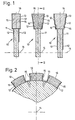
- Figur 1: Teilausschnitte von Werkzeugen mit unterschiedlich ausgebildeten Bearbeitungselementen im Querschnitt und
- Figur 2: ein Schnitt nach der Linie II-II der Figur 1 mit Bearbeitungselementen und einer Verschleißschutzschicht, die eine Diamantkörnung enthalten.
- Figure 1: partial cutouts of tools with differently designed machining elements in cross section and
- Figure 2: a section along the line II-II of Figure 1 with processing ele elements and a wear protection layer containing a diamond grit.
Bei dem in der Figur 1 und 2 dargestellten Werkzeug handelt es sich um ein Sägeblatt, das um eine Achse 14 drehbar gelagert ist. Das Werkzeug 10 trägt auf einem scheibenförmigen Werkzeuggrundkörper 11 mehrere, im Abstand zueinander stehende segmentartige Bearbeitungselemente 13, die entsprechend der Figur 1 von verschiedenartigem Querschnitt sein können.The tool shown in FIGS. 1 and 2 is a saw blade which is rotatably mounted about an
Die Bearbeitungselemente 13 sind an ihren am eigentlichen Bearbeitungsvorgang nicht beteiligten passiven Seiten 15, das heißt ihren beiden Außenseiten sowie ihrer Vorder- und Rückseite mit einer aus einem relativ weichen Werkstoff bestehenden Verschleißschutzschicht 12 ummantelt, während die aktive außenliegende Seite 16 eines Bearbeitungselementes 13 frei ist von einer Verschleißschutzschicht bzw. während der Benutzung des Werkzeuges frei wird, da das Werkzeug 10 herstellungsbedingt vollständig mit einer Schutzschicht ummantelt sein kann bzw. auch der tragende Werkzeuggrundkörper 11 entsprechend den Darstellungen in Figur 1 mit der Schutzschicht versehen sein kann.The
Je nach der Geometrie der Bearbeitungselemente 13 oder des gesamten Werkzeuges 10 können also sämtliche am Bearbeitungsvorgang nicht teilnehmenden Flächen oder Kanten teilweise oder vollständig mit der aus einem weichen Werkstoff bestehenden Verschleißschutzschicht umgeben sein, so daß Erosions-, Kavitations- und Korrosionsverschleiß sowie Kombinationen dieser Verschleißerscheinungen an allen Stellen des Werkzeugs 10 vermieden werden, die einer Gefährdung ausgesetzt sind. Aus diesem Grunde ist die erfindungsgemäße Verschleißschutzschicht 12 auch geeignet, Abtragserscheinungen an beliebigen Werkzeughaltern, beispielsweise Bohrkronen, Bohrgestängen, Sägestammblättern und dergleichen zu verhindern, die sowohl mit diamanthaltigen Bearbeitungselementen als auch mit nicht diamanthaltigen Bearbeitnngselementen 13 bestückt sein können. Bei der in der Zeichnung wiedergegebenen Ausführungsform nach Figur 2 handelt es sich um diamantkornhaltige Bearbeitungselemente 13 sowie um eine Schutzschicht, die ebenfalls mit Diamantkorn durchsetzt ist. Die übrigen Ausführungen der Figur 1 zeigen hingegen Schutzschichten ohne Hartstoffkörnung.Depending on the geometry of the
Die Art der Aufbringung der Verschleißschutzschicht 12 ist abhängig von ihrem Werkstoff.The type of application of the
Der Zeitpunkt des Aufbringens der Verschleißschutzschicht 12 hängt im wesentlichen vom gewählten Beschichtungs-Verfahren ab. Besonders geeignet sind galvanische Schichten und Lötschichten, da sie sowohl auf losen Werkzeugsegmenten bzw. Bearbeitungselementen aufgebracht werden können, die dann in der Regel auf die Werkzeughalter hart aufgelötet werden, als auch auf fertig hartgelöteten oder geschweißten Werkzeug/Halter-Einheiten.The point in time at which the
Darüber hinaus lassen sich die erfindungsgemäßen Verschleißschutzschichten bei bei Bedarf mehrmals und gegebenenfalls vor Ort auftragen, wenn ein entsprechender Verschleiß dies erforderlich machen sollte. Sowohl das Tampongalvanisieren als auch die Verwendung von Lötpastensind grundsätzlich zur Ausbildung der erfindungsgemäßen Verschleißschutzschicht 12 geeignet. Zum Aufbringen einer dünnen Verschleißschutzschicht 12 eignet sich auch das Tauchen in bzw. das Aufpinseln von CuSO4- oder AgNO3- Losungen.In addition, the wear protection layers according to the invention can be added Apply several times if necessary and, if necessary, on site if appropriate wear should make this necessary. Both tampon electroplating and the use of solder pastes are basically suitable for forming the
Claims (7)
Applications Claiming Priority (4)
| Application Number | Priority Date | Filing Date | Title |
|---|---|---|---|
| DE3418815 | 1984-05-21 | ||
| DE19843418815 DE3418815A1 (en) | 1984-05-21 | 1984-05-21 | Tool, having a wear-resistant layer, for machining metallic and non-metallic materials |
| DE19843433729 DE3433729A1 (en) | 1984-09-14 | 1984-09-14 | Tool for machining metallic and non-metallic materials |
| DE3433729 | 1984-09-14 |
Publications (2)
| Publication Number | Publication Date |
|---|---|
| EP0163843A2 true EP0163843A2 (en) | 1985-12-11 |
| EP0163843A3 EP0163843A3 (en) | 1988-08-03 |
Family
ID=25821390
Family Applications (1)
| Application Number | Title | Priority Date | Filing Date |
|---|---|---|---|
| EP85104047A Withdrawn EP0163843A3 (en) | 1984-05-21 | 1985-04-03 | Tool with a wear protection layer |
Country Status (1)
| Country | Link |
|---|---|
| EP (1) | EP0163843A3 (en) |
Cited By (9)
| Publication number | Priority date | Publication date | Assignee | Title |
|---|---|---|---|---|
| WO1991002626A1 (en) * | 1989-08-25 | 1991-03-07 | Tyrolit Schleifmittelwerke Swarovski K.G. | Trimming up abrading discs |
| EP0433692A2 (en) * | 1989-11-23 | 1991-06-26 | Toyoda Koki Kabushiki Kaisha | Segmentee grinding wheel |
| FR2662963A1 (en) * | 1990-06-11 | 1991-12-13 | Combustible Nucleaire | ABRASIVE CUTTING ELEMENT AND METHOD FOR MANUFACTURING SUCH AN ELEMENT. |
| WO1996007521A1 (en) * | 1994-09-05 | 1996-03-14 | Ehwa Diamond Ind. Co., Ltd. | Saw blade segment with silver solder |
| EP1022094A2 (en) * | 1998-10-26 | 2000-07-26 | Kaiser, Michael, Dr. Ing. | Diamond dressing disc |
| EP1270126A1 (en) * | 2001-06-29 | 2003-01-02 | Turbolite AG | Circular saw blade with wear-resitant regions on its support disc |
| EP1808250A1 (en) * | 2006-01-13 | 2007-07-18 | WIKUS-Sägenfabrik Wilhelm H. Kullmann GmbH & Co. KG. | Saw blade with body und teeth arrangement with an edge with wear protection layer |
| EP2094424A1 (en) * | 2006-11-16 | 2009-09-02 | Shinhan Diamond Ind. Co., Ltd. | Diamond tool and method for manufacturing segment thereof |
| DE102020128920A1 (en) | 2020-11-03 | 2022-05-05 | WIKUS-Sägenfabrik Wilhelm H. Kullmann GmbH & Co. KG | super alloy saw blade |
Citations (4)
| Publication number | Priority date | Publication date | Assignee | Title |
|---|---|---|---|---|
| BE621587A (en) * | ||||
| BE718758A (en) * | 1968-07-30 | 1968-12-31 | ||
| FR1568331A (en) * | 1968-03-29 | 1969-05-23 | ||
| JPS57184674A (en) * | 1981-05-06 | 1982-11-13 | Niro Inoue | Stone cutting diamond blade |
-
1985
- 1985-04-03 EP EP85104047A patent/EP0163843A3/en not_active Withdrawn
Patent Citations (4)
| Publication number | Priority date | Publication date | Assignee | Title |
|---|---|---|---|---|
| BE621587A (en) * | ||||
| FR1568331A (en) * | 1968-03-29 | 1969-05-23 | ||
| BE718758A (en) * | 1968-07-30 | 1968-12-31 | ||
| JPS57184674A (en) * | 1981-05-06 | 1982-11-13 | Niro Inoue | Stone cutting diamond blade |
Non-Patent Citations (1)
| Title |
|---|
| PATENT ABSTRACTS OF JAPAN, Band 7, Nr. 29 (M-191)[1174], 5. Februar 1983; & JP-A-57 184 674 (NIROU INOUE) 13-11-1982 * |
Cited By (13)
| Publication number | Priority date | Publication date | Assignee | Title |
|---|---|---|---|---|
| WO1991002626A1 (en) * | 1989-08-25 | 1991-03-07 | Tyrolit Schleifmittelwerke Swarovski K.G. | Trimming up abrading discs |
| EP0433692A2 (en) * | 1989-11-23 | 1991-06-26 | Toyoda Koki Kabushiki Kaisha | Segmentee grinding wheel |
| EP0433692A3 (en) * | 1989-11-23 | 1992-01-02 | Toyoda Koki Kabushiki Kaisha | Segmentee grinding wheel |
| FR2662963A1 (en) * | 1990-06-11 | 1991-12-13 | Combustible Nucleaire | ABRASIVE CUTTING ELEMENT AND METHOD FOR MANUFACTURING SUCH AN ELEMENT. |
| EP0461951A1 (en) * | 1990-06-11 | 1991-12-18 | Supradiamant | Abrasive cutting element and process to manufacture such an element |
| WO1996007521A1 (en) * | 1994-09-05 | 1996-03-14 | Ehwa Diamond Ind. Co., Ltd. | Saw blade segment with silver solder |
| EP1022094A2 (en) * | 1998-10-26 | 2000-07-26 | Kaiser, Michael, Dr. Ing. | Diamond dressing disc |
| EP1022094A3 (en) * | 1998-10-26 | 2002-11-20 | Kaiser, Michael, Dr. Ing. | Diamond dressing disc |
| EP1270126A1 (en) * | 2001-06-29 | 2003-01-02 | Turbolite AG | Circular saw blade with wear-resitant regions on its support disc |
| EP1808250A1 (en) * | 2006-01-13 | 2007-07-18 | WIKUS-Sägenfabrik Wilhelm H. Kullmann GmbH & Co. KG. | Saw blade with body und teeth arrangement with an edge with wear protection layer |
| EP2094424A1 (en) * | 2006-11-16 | 2009-09-02 | Shinhan Diamond Ind. Co., Ltd. | Diamond tool and method for manufacturing segment thereof |
| EP2094424A4 (en) * | 2006-11-16 | 2014-03-05 | Shinhan Diamond Ind Co Ltd | Diamond tool and method for manufacturing segment thereof |
| DE102020128920A1 (en) | 2020-11-03 | 2022-05-05 | WIKUS-Sägenfabrik Wilhelm H. Kullmann GmbH & Co. KG | super alloy saw blade |
Also Published As
| Publication number | Publication date |
|---|---|
| EP0163843A3 (en) | 1988-08-03 |
Similar Documents
| Publication | Publication Date | Title |
|---|---|---|
| DE1477118C3 (en) | Cutting tool for machining | |
| DE102006001816B4 (en) | Saw blade with a base body and teeth with a cutting edge with a wear protection layer | |
| DE3706868A1 (en) | DRESSING TOOL FOR GRINDING WHEELS | |
| DE2434714C2 (en) | Saw wire for a wire saw and method of manufacturing | |
| EP0163843A2 (en) | Tool with a wear protection layer | |
| DE4338077A1 (en) | Honing element | |
| EP0508941B1 (en) | Tool for machining of materials | |
| DE1758823B2 (en) | Core drill | |
| DE2306780A1 (en) | TOOTHED TOOL FOR FINISHING GEAR WHEELS | |
| EP0540566B1 (en) | Cutting tool | |
| DE102019117799B4 (en) | Cutting tool with asymmetrical teeth with cutting particles | |
| DE3433729A1 (en) | Tool for machining metallic and non-metallic materials | |
| EP1027476A1 (en) | Cutting tool and method for coating cutting tools | |
| DE3418815A1 (en) | Tool, having a wear-resistant layer, for machining metallic and non-metallic materials | |
| EP1820618B1 (en) | Cutting tool | |
| EP0857552B1 (en) | Stone machining tool with improved first cut behavior | |
| EP0530528B1 (en) | Grinding tool | |
| AT404915B (en) | SAW WITH A BASE AND TEETH AND METHOD FOR PRODUCING A SAW | |
| EP1156905B1 (en) | Grinding or cutting tool | |
| EP1673192B1 (en) | Reamer | |
| DE102011009364A1 (en) | Cutting tool e.g. drill bit for processing workpiece e.g. timber material, has metal foamed main portion with open cell wall comprising pores for removing cut material during geometric indefinite cutting of workpiece | |
| DE10316171A1 (en) | Sawblade for processing machine, is particularly for processing glass, mirrors and other materials in Tiffany technique, particularly with an approximately rectangular cross-section | |
| DE102019117796A1 (en) | Cutting tool with buffer particles | |
| DD273996A1 (en) | HARDWARE-COATED CUTTING TOOL, ESPECIALLY KNIVES FOR CUTTING PAPER, PAPER, LEATHER, TEXTILES AND CHEMICALS | |
| EP1458528A2 (en) | Cutting or grinding or drilling tool having low-height cutting or grinding layers, and method for producing a such a tool |
Legal Events
| Date | Code | Title | Description |
|---|---|---|---|
| PUAI | Public reference made under article 153(3) epc to a published international application that has entered the european phase |
Free format text: ORIGINAL CODE: 0009012 |
|
| AK | Designated contracting states |
Designated state(s): BE DE FR GB IT NL SE |
|
| PUAL | Search report despatched |
Free format text: ORIGINAL CODE: 0009013 |
|
| AK | Designated contracting states |
Kind code of ref document: A3 Designated state(s): BE DE FR GB IT NL SE |
|
| 17P | Request for examination filed |
Effective date: 19890203 |
|
| 17Q | First examination report despatched |
Effective date: 19900910 |
|
| STAA | Information on the status of an ep patent application or granted ep patent |
Free format text: STATUS: THE APPLICATION IS DEEMED TO BE WITHDRAWN |
|
| 18D | Application deemed to be withdrawn |
Effective date: 19910321 |
|
| RIN1 | Information on inventor provided before grant (corrected) |
Inventor name: DIETRICH, RAINER, DR. DIPL.-ING. Inventor name: HILSCH, GEORG, DIPL.-ING. Inventor name: SASSE, KARL-MICHAEL, DIPL.-ING. |