EP0163654B1 - Apparatus and method for fusing battery terminals - Google Patents
Apparatus and method for fusing battery terminals Download PDFInfo
- Publication number
- EP0163654B1 EP0163654B1 EP84903581A EP84903581A EP0163654B1 EP 0163654 B1 EP0163654 B1 EP 0163654B1 EP 84903581 A EP84903581 A EP 84903581A EP 84903581 A EP84903581 A EP 84903581A EP 0163654 B1 EP0163654 B1 EP 0163654B1
- Authority
- EP
- European Patent Office
- Prior art keywords
- coil
- battery
- mold cavity
- bushing
- power level
- Prior art date
- Legal status (The legal status is an assumption and is not a legal conclusion. Google has not performed a legal analysis and makes no representation as to the accuracy of the status listed.)
- Expired
Links
- 238000000034 method Methods 0.000 title claims abstract description 14
- 238000010438 heat treatment Methods 0.000 claims abstract description 67
- 230000006698 induction Effects 0.000 claims abstract description 53
- 230000004927 fusion Effects 0.000 claims abstract description 37
- 238000002844 melting Methods 0.000 claims abstract description 20
- 230000008018 melting Effects 0.000 claims abstract description 20
- 230000000694 effects Effects 0.000 claims abstract description 12
- 239000004033 plastic Substances 0.000 claims abstract description 8
- 230000007423 decrease Effects 0.000 claims abstract description 5
- 229910000859 α-Fe Inorganic materials 0.000 claims abstract description 3
- 230000003247 decreasing effect Effects 0.000 claims description 8
- 230000004044 response Effects 0.000 claims description 6
- 238000000465 moulding Methods 0.000 claims description 4
- 230000002708 enhancing effect Effects 0.000 claims description 2
- 239000007787 solid Substances 0.000 claims 2
- 239000012815 thermoplastic material Substances 0.000 claims 1
- 239000012141 concentrate Substances 0.000 abstract description 2
- 238000004519 manufacturing process Methods 0.000 description 9
- RYGMFSIKBFXOCR-UHFFFAOYSA-N Copper Chemical compound [Cu] RYGMFSIKBFXOCR-UHFFFAOYSA-N 0.000 description 8
- 229910052802 copper Inorganic materials 0.000 description 8
- 239000010949 copper Substances 0.000 description 8
- 230000008878 coupling Effects 0.000 description 6
- 238000010168 coupling process Methods 0.000 description 6
- 238000005859 coupling reaction Methods 0.000 description 6
- 239000003990 capacitor Substances 0.000 description 4
- 238000001816 cooling Methods 0.000 description 4
- 230000002441 reversible effect Effects 0.000 description 4
- 125000006850 spacer group Chemical group 0.000 description 4
- 239000002253 acid Substances 0.000 description 3
- 238000005192 partition Methods 0.000 description 3
- 238000012545 processing Methods 0.000 description 3
- HSFWRNGVRCDJHI-UHFFFAOYSA-N alpha-acetylene Natural products C#C HSFWRNGVRCDJHI-UHFFFAOYSA-N 0.000 description 2
- 238000010276 construction Methods 0.000 description 2
- 125000002534 ethynyl group Chemical group [H]C#C* 0.000 description 2
- 238000012986 modification Methods 0.000 description 2
- 230000004048 modification Effects 0.000 description 2
- 230000003287 optical effect Effects 0.000 description 2
- 238000012546 transfer Methods 0.000 description 2
- 239000004809 Teflon Substances 0.000 description 1
- 229920006362 Teflon® Polymers 0.000 description 1
- 230000002411 adverse Effects 0.000 description 1
- 239000000498 cooling water Substances 0.000 description 1
- 230000002950 deficient Effects 0.000 description 1
- 238000013461 design Methods 0.000 description 1
- 238000010586 diagram Methods 0.000 description 1
- 229920001971 elastomer Polymers 0.000 description 1
- 239000000806 elastomer Substances 0.000 description 1
- 238000001914 filtration Methods 0.000 description 1
- 239000012530 fluid Substances 0.000 description 1
- 238000007499 fusion processing Methods 0.000 description 1
- 239000007789 gas Substances 0.000 description 1
- 239000012212 insulator Substances 0.000 description 1
- 229910000464 lead oxide Inorganic materials 0.000 description 1
- 230000000670 limiting effect Effects 0.000 description 1
- 239000000463 material Substances 0.000 description 1
- 239000002184 metal Substances 0.000 description 1
- 229910052751 metal Inorganic materials 0.000 description 1
- 239000007769 metal material Substances 0.000 description 1
- 230000002093 peripheral effect Effects 0.000 description 1
- 230000008569 process Effects 0.000 description 1
- 230000001681 protective effect Effects 0.000 description 1
- 230000002829 reductive effect Effects 0.000 description 1
Images


Classifications
-
- B—PERFORMING OPERATIONS; TRANSPORTING
- B23—MACHINE TOOLS; METAL-WORKING NOT OTHERWISE PROVIDED FOR
- B23K—SOLDERING OR UNSOLDERING; WELDING; CLADDING OR PLATING BY SOLDERING OR WELDING; CUTTING BY APPLYING HEAT LOCALLY, e.g. FLAME CUTTING; WORKING BY LASER BEAM
- B23K13/00—Welding by high-frequency current heating
-
- H—ELECTRICITY
- H01—ELECTRIC ELEMENTS
- H01M—PROCESSES OR MEANS, e.g. BATTERIES, FOR THE DIRECT CONVERSION OF CHEMICAL ENERGY INTO ELECTRICAL ENERGY
- H01M50/00—Constructional details or processes of manufacture of the non-active parts of electrochemical cells other than fuel cells, e.g. hybrid cells
- H01M50/50—Current conducting connections for cells or batteries
- H01M50/543—Terminals
- H01M50/552—Terminals characterised by their shape
- H01M50/561—Hollow metallic terminals, e.g. terminal bushings
-
- Y—GENERAL TAGGING OF NEW TECHNOLOGICAL DEVELOPMENTS; GENERAL TAGGING OF CROSS-SECTIONAL TECHNOLOGIES SPANNING OVER SEVERAL SECTIONS OF THE IPC; TECHNICAL SUBJECTS COVERED BY FORMER USPC CROSS-REFERENCE ART COLLECTIONS [XRACs] AND DIGESTS
- Y02—TECHNOLOGIES OR APPLICATIONS FOR MITIGATION OR ADAPTATION AGAINST CLIMATE CHANGE
- Y02E—REDUCTION OF GREENHOUSE GAS [GHG] EMISSIONS, RELATED TO ENERGY GENERATION, TRANSMISSION OR DISTRIBUTION
- Y02E60/00—Enabling technologies; Technologies with a potential or indirect contribution to GHG emissions mitigation
- Y02E60/10—Energy storage using batteries
-
- Y—GENERAL TAGGING OF NEW TECHNOLOGICAL DEVELOPMENTS; GENERAL TAGGING OF CROSS-SECTIONAL TECHNOLOGIES SPANNING OVER SEVERAL SECTIONS OF THE IPC; TECHNICAL SUBJECTS COVERED BY FORMER USPC CROSS-REFERENCE ART COLLECTIONS [XRACs] AND DIGESTS
- Y02—TECHNOLOGIES OR APPLICATIONS FOR MITIGATION OR ADAPTATION AGAINST CLIMATE CHANGE
- Y02P—CLIMATE CHANGE MITIGATION TECHNOLOGIES IN THE PRODUCTION OR PROCESSING OF GOODS
- Y02P70/00—Climate change mitigation technologies in the production process for final industrial or consumer products
- Y02P70/50—Manufacturing or production processes characterised by the final manufactured product
Definitions
- the present invention relates generally to the manufacture of lead acid storage batteries, and more particularly, to an improved apparatus and method for fusing battery cell terminal posts to respective bushings in the battery casing to form the external terminals of the completed battery.
- Another object is to provide an apparatus as characterized above which permits reliable and effective fusion of the terminal post and bushings in a relatively short time, and thus, is adaptable for use in a fully automated battery production line.
- a further object is to provide an apparatus of the foregoing type which permits quick automated fusion of the terminal posts and cover bushings while reliably effecting proper fusion depths of the finished terminals, preventing cover melting or damage, and obtaining completed battery terminals with relatively good surface appearance.
- the invention provides an apparatus for fusing lead components of a battery being assembled comprising
- the illustrated battery 10 includes a case 14, preferably made of plastic, formed with a plurality of internal divider partitions 15 that form individual compartments for containing respective battery cell elements 181 or 18T.
- the illustrated battery 10 includes six cell elements, namely two outermost terminal cell elements 18T at opposed ends of the battery and four intermediate cell elements 181 located therebetween.
- the electrode plates of like polarity of each battery cell element 181, 18T are electrically coupled together by a respective cast lead lug-strap 191 or 19T.
- the lug-straps 19T for the terminal cell elements 18T are provided with an upstanding terminal post 20 which may be integrally formed with the strap 19T, or alternatively, the post 20 may be separately cast or otherwise mounted on the strap 19T.
- the cell elements 181, 18T in the case 14 are cast thereon.
- the lug straps 191 Prior to closing the top of the battery, the lug straps 191 are suitably joined together through the partitions 15 (as shown in FIG. 3) and a cover 21 with terminal bushings 22 mounted therein is thereafter positioned onto the case 14 with the terminal posts 20 extending co-axially through the bushings 22 (FIG. 4).
- the bushings 22 have a slight upward external taper, shaped according to industry standards, and a tapered axial opening 24, shaped generally complimentary to the terminal posts 20.
- the lowermost end of the bushing opening 24 has an outwardly flared chamfer 24a (FIG. 3) for guiding the terminal post 20 into proper seating in the bushing during assembly of the cover 21 onto the case 14.
- the terminal posts 20 are of sufficient height that upon assembly on the cover 21 the tops of the posts 20 are flush with the tops of the bushings 22 (FIG. 4).
- the bushings 22 each preferably have a ribbed peripheral mounting portion 25 that is adapted to provide a strong mechanical connection with the plastic cover 21 while forming an effective seal about the periphery of the cover and bushing.
- a battery terminal fusion apparatus which has induction heating means for quickly, reliably and automatically heating, melting and fusing the ends of the terminal posts and cover bushings to proper and consistent fusion depths with good surface appearance, while not melting or otherwise damaging the plastic battery case and cover.
- FIGS. 6 and 7 there is shown an illustrative terminal post and bushing fusion apparatus 30 which preferably is included in an automated production line having a conveyer track 31 upon which batteries in assembly are moved through successive operating stations.
- the track 31 is supported on a structural frame 32 and comprises a pair of laterally spaced elongated bottom track members upon which the batteries ride.
- An upstanding side-reference rail 34 is located immediately adjacent the track, and suitable chain conveyer means, generally indicated at 35, is provided for moving the batteries along the tracks.
- a plurality of pivotable stops 36 are mounted on the underside of the track.
- the stops 36 each are pivotably mounted on respective pivot shafts 38 and have one end coupled to a rod 39a of a respective air cylinder 39 fixed at its opposite end to the frame 32.
- batteries may be successively stopped at a ready station 40 for the fusion apparatus 30 with the cover 21 mounted on the case 14 and the terminal posts 20 extending upwardly through the respective cover bushings 22, as previously described.
- the cylinders 39 are actuated to retract the stops 36, the batteries are advanced along the track 31 to the succeeding operating stations, and the stops 36 are again raised by reverse actuation of the air cylinders 39, thereby successively moving batteries from the ready station 40 to the terminal fusion apparatus 30 and from the fusion apparatus to the next station.
- the battery is firmly positioned against the side-reference rail 34 by actuation of a cylinder 41, the rod 41a of which extends into engagement with the side of the battery and moves it into proper position against the rail 34.
- a limited range photosensor 42 is mounted on the opposite side of the rail 34 immediatedly adjacent an aperture 44 therein and is adapted to sense the presence of a battery only when positioned against the side rail.
- the terminal fusion apparatus 30 includes a pair of induction heating coils 50 disposed in an aligned relation to the terminal posts 20 and bushings 22 of a battery properly positioned at the fusion apparatus, and means are provided for effecting relative movement between the battery and coils 50 such that the ends of the battery terminal posts and bushings are positionable in operative relation to the induction heating coils.
- an elevator 51 is mounted immediately below the track 31 and includes a pair of upstanding legs 52 that can be selectively raised and lowered with respect to the track 31.
- the elevator 51 is secured on the transverse mounting plate 54 fixed at the upper end of a rod 55a of an air cylinder 55 such that actuation of the cylinder 55 and extension of the rod 55a will lift the elevator causing the legs 52 to be raised above the level of the track, lifting the battery off the track and positioning terminal posts 20 and bushings 22 thereof into the underside inductance heating coils 50.
- Reverse actuation of the air cylinder 55 lowers the elevator 51 and repositions the battery onto the track 31 for subsequent movement along the production line.
- the traverse mounting plate 54 is supported for vertical movement on upstanding guide rods 56 (FIG. 6).
- stops 58 are threadably mounted on upstanding bolts 59 carried by the frame 32.
- a magnetic switch 60 on the cylinder 55 senses the raised condition on the elevator 51, and a switch 61 senses the lowered condition.
- the induction heating coils 50 in this instance are supported in cantilever fashion from the cabinet 65 of the induction generator of the terminal fusion apparatus 30 immediately below a protective hood positioned to prevent inadvertent contact with the coils 50, and are rigidly studded to a coil brace 66 for mechanical integrity and strength.
- the coils are carried by a T-buss 68 which in turn is supported at a desired elevation by a dropper buss 69 fixed to the induction output plates of the induction generator (FIGS. 7 and 8).
- the coils 50 preferably each comprise a continuous length of copper tubing formed in a helix configuration of concentric circular turns 50a, 50b, 50c (FIGS. 4 and 10), and the coils 50 are interconnected to form part of a continuous induction heating and cooling circuit 70a-70g (FIG. 8).
- Such copper tubing circuit in this instance includes an inlet section 70a communicating from the cabinet 65 and supported by the dropper buss 69, a T-buss section 70b communicating with the inlet section 70a and supported by the T-buss 68, a section 70c communicating with the T-buss section 70b and forming one of the coils 50, a section 70d communicating between the section 70c and a section 70e forming the other coil 50, a T-buss section 70f communicating with the section 70e and supported on an opposite side of the T-buss 68 as the section 70b, and an outlet section 70g communicating between the T-buss section 70f and the cabinet 65 and supported by the dropper buss 69 on the side opposite the section 70b.
- the illustrated dropper buss 69 comprises a pair of copper plates 69a, 69b separated by an insulating spacer 75a and fixed to the outside of the cabinet 65.
- the T-buss 68 comprises a pair of L-shaped copper plates 68a, 68b separated by an insulating spacer 75b coupled together by bolts 76 (FIG. 8), and mounted in an outwardly extended relation to the dropper buss 69 by bolts 78 (FIG. 9).
- the T-buss 68 further includes a forward plate 68c secured forwardly of the L-shaped plates 68a, 68b by bolts 79 and separated therefrom by an insulating spacer 75c. Forwardly extending insulator spacers 75d separate inlet and outlet legs of each coil 50.
- the coils 50 in this case each are supported by an angle flange 80 secured to the T-buss 68 by bolts 81 (FIG. 11).
- the coils 50 are suspended from an outwardly extending horizontal flange of each angle flange 80 by depending studs 82 having inwardly angled ends 82a fixed to the coil turns.
- bolts 84 in this case are connected between the underside of the coil brace 66 and the angle flanges 80 (FIGS. 6 and 7). It will be understood that suitable seals and insulating means are provided between the various buss plates and copper tubing couplings so as to form a continuous low resistance electrical and leak-free fluid circuit through the copper tubing sections 70a-70g.
- the input and output sections 70a and 70g of the copper tubing can thereby be electrically coupled to a high voltage, induction generator 90 of a known type, for example, on the order of 20 kilowatt capacity at 450 khz, contained within the cabinet 65 such that upon energization of the generator 90 (FIG. 7) current flow through the tubing circuit 70a-70g induces high level heating in materials located in axial relation to the coils 50.
- induction generators of other capacities and with higher or lower frequencies could alternatively be used.
- Such induction heating has been found to permit substantially instantaneous heating of lead terminal posts 20 and bushings 22 located in operative relation to the coils 50 to temperatures in excess of 1000°F, well above the melting point of lead.
- cooling water may be circulated through the tubing sections 70a-70g, cooling lines in the generator coupled to the tubing sections, and then through a radiator 91, in this instance mounted on the cabinet 65.
- each of the induction heating coils 50 removably supports a mold insert 95 in depending fashion from the underside thereof, each of which is formed with a mold cavity 96 for receiving the terminal post and cover bushing of a battery to be fused and for conforming melted ends thereof to the proper configuration following energization of the coils.
- the illustrated mold inserts 95 each have a cylindrical shape arid are formed with an annular shoulder 98 (FIG. 4) positionable against the underside of the lowermost coil turn 50a, and an annular groove 99 formed in upwardly spaced relation to the shoulder 98 for receiving a flexible retainer washer 100, preferably made of temperature resistant elastomer, which enables the mold insert 95 to be captively supported by the lowermost coil turn 50a.
- the cavity 96 of the mold insert 95 is shaped in substantial conformity to the bushing 22 so as to form an uppermost end of the battery terminal upon melting and fusion of the upper ends of a bushing and terminal post positioned therein.
- the lowermost end of the cavity 96 is formed with an outwardly flared chamfer 96a.
- the upperside of the mold insert 95 preferably is enclosed by a relatively thin walled apertured partition 101 that serves to prevent metal from contacting the coil 50 during the fusion operation, while permitting expanding gases to escape through apertures 102.
- the mold insert 95 preferably is made of Teflon which unexpectedly has been found to withstand the relatively high temperatures that occur during the fusion operation and which forms the fused terminals with a relatively smooth clean surface. Such mold inserts 95 have been found to be adaptable for fusing 3000 or more terminals without replacement. It will be appreciated by one skilled in the art, however, that the inserts 95 may be economically produced and are easily replaceable on a regular basis by simply removing the flexible retainer washer 100.
- the turns 50a-50c of each induction heating coil 50 are arranged so as to enhance quick and reliable heating, melting and fusion of the uppermost ends of the battery terminal post 20 and cover bushing 22 position therein while not adversely effecting the portions of the plastic cover 21 immediately adjacent the bushing.
- the lowermost turn 50a of each coil surrounds the mold insert 95 at a point about midway down the bushing and terminal post cavity 96 and the coil turns 50b, 50c are of relatively smaller diameter, corresponding substantially into the diameter of the upper end of the terminal to be fused, and are located in vertically spaced relation above the mold insert 95.
- Such a coil arrangement has been found to concentrate induction heating effects onto the upper ends of a bushing and terminal post disposed in the mold cavity 96 so as to effect melting and fusion of the ends without significantly affecting the lower parts thereof adjacent that battery cover.
- a current concentrating insert 105 is supported within the two uppermost coil turns 50b, 50c, as shown in FIG. 10.
- the insert 105 preferably is made of ferrite, or such other metallic material which has the affect of intensifying or concentrating current induced by the coil 50 onto the upper ends of the bushing and terminal post located in operative relation thereto.
- the use of such an induction heating coil 50 and current concentrating insert 105 arrangement has been unexpectedly found to enhance heating of the lead bushing and terminal post parts such that they can be consistently melted to fusion depths of as much as 3/8 of an inch in less than three seconds.
- means for controlling the induction heating cycle such that the coils 50 are instanteously energized to a predetermined full power level, are maintained at such full power for a predetermined relatively short period to melt the bushing and terminal post ends, and then the power level is gradually decreased in a uniform and controlled manner for fusing the terminals with a relatively smooth surface.
- the power level of the radio frequency generator 90 is controlled by an SCR power control 110 (FIG. 14) which in turn is activated by a Master Controller 111 adapted to control the various operating functions of the fusion apparatus 30, as will become apparent.
- the Master Controller 111 Upon positioning of the terminal posts 20 and bushings 22 of a battery into operative relation with the induction heating coils 50, the Master Controller 111 is adapted to energize the SCR power control 110, which energizes the induction heating generator to a full power capacity, as graphically depicted in FIG. 13. After a predetermined period, as timed by the Master Controller 111, the Master Controller will shut off the supply of power to the SCR power control.
- a down-slope heat control circuit 112 is provided, as shown in FIGS. 12 and 14.
- the down-slope heat control circuit 112 is coupled to the Master Controller 111 by input terminals 114, 115, and a transformer 116 is coupled between the input terminals 114, 115 and a diode bridge 118.
- a filtering capacitor 119 is coupled across the bridge 118 in a line 120, and a current limiting resistor 121 and a photo diode 122a of a optical coupling device 122 also are coupled across the bridge in a line 124.
- the Master Controller 111 will communicate an output voltage (such as 110V) to the input terminals 114, 115, which is reduced by the transformer 116 to a lower AC voltage, rectified by the diode bridge 118 and filtered by the capacitor 119 to produce a DC current flow through the photo diode 122a.
- Such current flow through the photo diode 122a activates a photo transistor 122b of the coupling device 122 in an R-C control circuit 128, which in turn allows a reference voltage, as established by potentiometer 126 having a DC power supply 129, to be communicated to output terminals 130, 131 coupling the down-slope heat control circuit 112 to the SCR power control 110.
- a capacitor 135 coupled in parallel across the potentiometer 126 charges to the reference voltage.
- the Master Controller 111 communicates a 11 OV output between input terminals 115, 116 of the down-slope heat control circuit 112
- the full reference voltage as established by the potentiometer 126, is communicated to the SCR power control 110 to nearly instantaneously energize the high-frequency generator 90 to its full power capacity.
- the Master Controller deenergizes the input terminals 115, 116 ofthe downslope heat control circuit 112, which turns off the photo diode 122a and photo transistor 122b of the optical coupling device 122.
- the voltage across the capacitor 135 in the R-C control circuit 128 continues to feed the output terminals 130, 131, but decays over a determined period, such as about one second, so that the voltage to the output terminals 130, 131, and the resulting power level of the generator controlled by the SCR power control 110, proportionally decreases in a controlled manner to zero.
- the period of full power operation of the induction heating generator 90 may be selectively effected by the Master Controller 111, while the controlled deenergization of the generator 90 may be controlled by the design of the down-slope heat control circuit 112.
- the controlled deenergization of the generator 90 may be controlled by the design of the down-slope heat control circuit 112.
- melting of the ends of battery terminal posts 20 and cover bushings 22 sufficient to achieve relatively constant and reliable fusion depths of between 1/4 and 3/8 inch can be achieved when the generator is operated at a full power level for about 2.5 seconds, and that unexpected good surface appearance of the fused terminals is achieved by deenergizing the inductance heating coils 50 from full power to zero power in the foregoing controlled fashion over a period of about one second.
- the terminals preferably are thereafter allowed to cool for a period of about eight seconds following complete deenergization of the induction heating coils prior to removal from the mold inserts 95.
- the entire fusion operation including raising and lowering of the battery into the inductance heating coils 50, can be carried out by the apparatus of the present invention well within a period of about 20 seconds. It will be understood by one skilled in the art that by virtue of such short process time, the apparatus 30 lends itself to efficient utilization in 'an automated battery production line where the individual processing operations are limited to short intervals.
- the Master Controller 111 which can be a conventional microprocessor-based programmable controller such as a Gould Modicon 84 Programmable Controller, can be programmed to effect the sequential operation of the terminal fusion apparatus 30 of the present invention and coordinate such operation with the transfer of batteries along the conveyor track 31.
- the Master Controller 111 can communicate with the apparatus 30 through conventional input and output modules which convert incoming signals from the various sensing devices of the apparatus to signal levels compatible with the controller and which convert output signals of the controller to signal levels compatible with the apparatus.
- appropriate sensing means may provide a signal to the Master Controller 111, in response to which the cylinder 41 is actuated to extend its rod 41a a and position the battery against the side-reference rail 34, which is sensed by the photo cell 42.
- the cylinder 41 is reverse actuated to withdraw the rod 41a, and the cylinder 55 actuated to raise the battery so that the terminal posts 20 and cover bushings 22 are disposed in operative relation to the respective induction heating coils 50, such raised position being sensed by the magnetic switch 60 on the cylinder 55.
- the Master Controller 111 may then energize the SCR power control 110 through the down-slope heat control circuit 112 to energize the generator 90 to full power level, maintain such full power level for a predetermined period of time to effect melting of the ends of the terminal post and bushings, and following such predetermined full power heating period, the Master Controller 111 will shut off the input voltage to the down-slope heat control circuit 112, which thereafter provides a controlled deenergization of the generator 90 and induction heating coils 50.
- the Master Controller 111 will cause the reverse actuation of air cylinder 55, lowering the elevator 51 and repositioning the battery on the conveyer track 31, as sensed by the switch 61, for transfer to the succeeding operating station, the entire cycle of operation being effected in a predetermined relatively short period of time.
- the fusion apparatus 30 of the present invention is adaptable for processing various different sized batteries.
- the T-buss 68 may be readily removed from the dropper buss 69 by removal of the mounting bolts 78 and replaced with a T-buss configuration to accommodate different terminal spacing and location on the battery.
- the lifting stroke of the elevator 51 also may be selectively adjusted by adjustment of the stops 58.
- the cabinet 65 in this case is mounted on an X-Y table 140 (FIGS.
- a gauge 146 is provided to facilitate location of a cabinet in the predetermined longitudinal position for a particular battery size, and a gauge 148 similarly is provided to facilitate transverse location of the cabinet.
Landscapes
- Engineering & Computer Science (AREA)
- Mechanical Engineering (AREA)
- Chemical & Material Sciences (AREA)
- Chemical Kinetics & Catalysis (AREA)
- Electrochemistry (AREA)
- General Chemical & Material Sciences (AREA)
- Lining Or Joining Of Plastics Or The Like (AREA)
- Connection Of Batteries Or Terminals (AREA)
Abstract
Description
- The present invention relates generally to the manufacture of lead acid storage batteries, and more particularly, to an improved apparatus and method for fusing battery cell terminal posts to respective bushings in the battery casing to form the external terminals of the completed battery.
- In the manufacture of lead acid storage batteries, it is customary to assemble the individual battery cells into a case with the terminal cells each having an upstanding lead terminal post located at opposed ends of the battery, to then position a cover having cylindrical lead bushings fixed therein onto the battery case with the terminal posts extending through respective of the bushings, and to then heat, melt, fuse, mold, cool and freeze the upper ends of the bushings and posts to form the finished battery terminals. Since the case and cover in modern day batteries commonly are made of plastic, care must be taken in fusing the terminal posts and bushings so as not to melt or otherwise damage the immediately adjacent portion of the cover, which can either render the battery defective or sufficiently weaken the seal and support between the cover and bushings as to create a potentially dangerous condition during use of the battery.
- Heretofore it has been common practice to fuse the terminal posts and bushings by melting the ends thereof by means of an acetylene torch which is manually held and operated. Not only does such procedure fail to lend itself to use in a fully automated battery production line, but the quality and depth of the fused areas of the terminal posts and bushings vary with the operator who performs the fusion process, and even between terminals of successive batteries fused by the same operator since there is no reliable means for controlling the degree offusion that is effected. Moreover, it is not easily determinable whether minimum required fusion depths are obtained i.e., generally considered to be between 1/8 and 3/16 inch (3.175 and 4.763 mm) as measured from the top of the finished terminal.
- While various proposals have been made for automatically fusing battery terminal posts and cover bushings by means of either acetylene torch heating, electrical resistance heating, or electrical induction heating, such proposals all have faced various drawbacks, including the inability to obtain reliable fusion depths within the requisite processing time, undesirable melting of the cover about the bushings and unacceptable appearance of the finished terminals. Since lead oxides contained within the lead bushings tend to float to the surface during melting, under some circumstances this has been found to result in unsightly irregularities in the surfaces of the finished battery terminals.
- It is an object of the present invention to provide an improved apparatus and method for fusing the terminal posts and casing bushings in forming battery terminals.
- Another object is to provide an apparatus as characterized above which permits reliable and effective fusion of the terminal post and bushings in a relatively short time, and thus, is adaptable for use in a fully automated battery production line.
- A further object is to provide an apparatus of the foregoing type which permits quick automated fusion of the terminal posts and cover bushings while reliably effecting proper fusion depths of the finished terminals, preventing cover melting or damage, and obtaining completed battery terminals with relatively good surface appearance.
- The invention provides an apparatus for fusing lead components of a battery being assembled comprising
- a frame,
- an induction heating coil,
- means for fixedly supporting said induction heating coil in predetermined orientation with respect to said frame,
- a mold disposed in concentric relation to said induction heating coil, said mold having a mold cavity for receiving said battery components to be fused,
- means for automatically locating said battery components to be fused in position below said mold,
- means for automatically raising said battery components into said mold cavity and into operative relation to said induction heating coil,
- means for generating high frequency oscillating current in said coil,
- induced current concentrating means disposed in concentric relation to said induction heating coil for concentrating an induced current flow in said battery components positioned in operative relation to said coil for heating, melting and fusing said battery components together and molding said components in finished fused form in response to the generation of a high-frequency oscillating current in said coil while the surrounding non-lead components of the battery being assembled remain substantially unaffected,
- said induction heating coil including a plurality of vertically arranged turns, said mold being supported by at least one of the turns of said coil, and said induced current concentrating means being supported by at least one other of said turns, and
- means for automatically lowering and removing said battery components from said mold cavity following fusing and molding thereof to finished form.
- The invention also provides a method for fusing the end of a lead battery cell terminal post to the end of a hollow lead bushing fixed in the case of a battery being assembled and within which the terminal post is concentrically disposed comprising
- supporting an induction heating coil,
- supporting said battery being assembled such that a terminal post and bushing thereof are in concentric operative relation to said induction heating coil, and
- energizing said coil to a first predetermined power level for generating a high-frequency oscillating current in said coil to induce current flow in a terminal post and bushing in operative relation to said coil, maintaining said power level for a first predetermined period for melting the ends of said terminal post and bushing by said induced current flow, and then continuously decreasing said power level to zero in a controlled manner for a second predetermined period of time to effect the fusion of the ends of the terminal post and bushing to a controlled depth, said second predetermined period being shorter than said first predetermined period.
- Embodiments of the invention will now be described with reference to the drawings, in which:
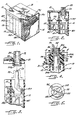
- FIGURE 1 is a perspective of a completed battery having terminals formed by the apparatus and method of the present invention;
- FIG. 2 is an enlarged section of one of the fused terminals of the battery shown in FIG. 1, taken the plane of line 2-2;
- FIG. 3 is an exploded vertical section showing a cover being positioned onto a battery case during assembly of the battery;
- FIG. 4 is a vertical section showing a battery with the cover assembled on the case and the battery operatively positioned in the illustrated apparatus, prior to fusing of the terminal post and cover bushing;
- FIG. 5 is a horizontal view of the top of the mold insert of the illustrated apparatus, taking in the plane of line 5-5 and FIG. 4;
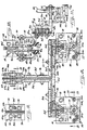
- FIG. 6 is a front elevational view of the illustrated terminal post fusion apparatus, taken in the plane of line 6-6 in FIG. 7;
- FIG. 7 is a side elevational view of the illustrated apparatus, taken in the plane of line 7-7 of FIG. 6;
- FIG. 8 is an enlarged fragmentary section of the induction heating coils and support of the illustrated apparatus, taken in the plane of line 8-8 in FIG. 6;
- FIGS. 9-11 are sections taken in the planes of lines 9-9, 10-10 and 11-11 in FIG. 8 respectively;
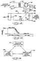
- . FIG. 12 is a schematic of a down-slope heat control circuit for the induction heating coils of the illustrated apparatus;
- FIG. 13 is a graphic illustration of the heat cycle of the illustrated apparatus; and
- FIG. 14 is a block diagram of the Master Controller of the illustrated apparatus.
- While the invention is susceptible to various modifications and alternative constructions, a certain illustrated embodiment thereof has been shown in the drawings and will be described below in detail. It should be understood, however, that there is no intention to limit the invention to the specific form disclosed, but on the contrary, the intention is to cover all modifications, alternative constructions and equivalents falling within the scope of the invention. Thus, while the present invention will be described in conjunction with the manufacture of a lead-acid storage battery for starting, lighting and ignition (hereinafter "SLI") applications, it will be appreciated that the invention is equally applicable for other battery applications. Similarly, while the invention will be described in connection with top terminal battery connections, the invention also is applicable to the connection of other battery components, such as side terminals, intercell connectors and the like.
- Referring now to FIGURE 1, there is shown an illustrative fully assembled and processed
SLI battery 10 havingterminals 11 formed on the top side thereof by a terminal fusion apparatus in accordance with the present invention. The illustratedbattery 10 includes acase 14, preferably made of plastic, formed with a plurality ofinternal divider partitions 15 that form individual compartments for containing respectivebattery cell elements battery 10 includes six cell elements, namely two outermostterminal cell elements 18T at opposed ends of the battery and fourintermediate cell elements 181 located therebetween. As is known in the art, the electrode plates of like polarity of eachbattery cell element strap 191 or 19T. The lug-straps 19T for theterminal cell elements 18T are provided with anupstanding terminal post 20 which may be integrally formed with the strap 19T, or alternatively, thepost 20 may be separately cast or otherwise mounted on the strap 19T. - During assembly of such batteries, it is customary to assemble the
cell elements case 14, either before or after thelug straps 191, 19T andterminal posts 20 are cast thereon. Prior to closing the top of the battery, thelug straps 191 are suitably joined together through the partitions 15 (as shown in FIG. 3) and acover 21 withterminal bushings 22 mounted therein is thereafter positioned onto thecase 14 with theterminal posts 20 extending co-axially through the bushings 22 (FIG. 4). Thebushings 22 have a slight upward external taper, shaped according to industry standards, and a taperedaxial opening 24, shaped generally complimentary to theterminal posts 20. The lowermost end of thebushing opening 24 has an outwardly flared chamfer 24a (FIG. 3) for guiding theterminal post 20 into proper seating in the bushing during assembly of thecover 21 onto thecase 14. In the illustrated embodiment, theterminal posts 20 are of sufficient height that upon assembly on thecover 21 the tops of theposts 20 are flush with the tops of the bushings 22 (FIG. 4). For reliably supporting thebushings 22 in thecover 21, thebushings 22 each preferably have a ribbedperipheral mounting portion 25 that is adapted to provide a strong mechanical connection with theplastic cover 21 while forming an effective seal about the periphery of the cover and bushing. - In accordance with the invention, a battery terminal fusion apparatus is provided which has induction heating means for quickly, reliably and automatically heating, melting and fusing the ends of the terminal posts and cover bushings to proper and consistent fusion depths with good surface appearance, while not melting or otherwise damaging the plastic battery case and cover. Referring now to FIGS. 6 and 7, there is shown an illustrative terminal post and
bushing fusion apparatus 30 which preferably is included in an automated production line having aconveyer track 31 upon which batteries in assembly are moved through successive operating stations. Thetrack 31 is supported on astructural frame 32 and comprises a pair of laterally spaced elongated bottom track members upon which the batteries ride. An upstanding side-reference rail 34 is located immediately adjacent the track, and suitable chain conveyer means, generally indicated at 35, is provided for moving the batteries along the tracks. - For stopping the batteries at predetermined operating stations along the
track 31, a plurality of pivotable stops 36 are mounted on the underside of the track. To selectively move the stops from a retracked position, shown in phantom in FIG. 6, to a raised battery stopping position shown in solid lines, the stops 36 each are pivotably mounted onrespective pivot shafts 38 and have one end coupled to a rod 39a of arespective air cylinder 39 fixed at its opposite end to theframe 32. Thus, as shown in FIG. 6, batteries may be successively stopped at a ready station 40 for thefusion apparatus 30 with thecover 21 mounted on thecase 14 and theterminal posts 20 extending upwardly through therespective cover bushings 22, as previously described. During the next operating cycle of the production line, thecylinders 39 are actuated to retract the stops 36, the batteries are advanced along thetrack 31 to the succeeding operating stations, and the stops 36 are again raised by reverse actuation of theair cylinders 39, thereby successively moving batteries from the ready station 40 to theterminal fusion apparatus 30 and from the fusion apparatus to the next station. Following advancement of a battery to theterminal fusion apparatus 30, the battery is firmly positioned against the side-reference rail 34 by actuation of a cylinder 41, the rod 41a of which extends into engagement with the side of the battery and moves it into proper position against therail 34. For sensing the proper position of a battery against the side-reference rail 34, alimited range photosensor 42 is mounted on the opposite side of therail 34 immediatedly adjacent anaperture 44 therein and is adapted to sense the presence of a battery only when positioned against the side rail. - In keeping with the invention, the
terminal fusion apparatus 30 includes a pair of induction heating coils 50 disposed in an aligned relation to the terminal posts 20 andbushings 22 of a battery properly positioned at the fusion apparatus, and means are provided for effecting relative movement between the battery and coils 50 such that the ends of the battery terminal posts and bushings are positionable in operative relation to the induction heating coils. In order to effect such relative movement in the illustrated embodiment, anelevator 51 is mounted immediately below thetrack 31 and includes a pair ofupstanding legs 52 that can be selectively raised and lowered with respect to thetrack 31. Theelevator 51 is secured on the transverse mountingplate 54 fixed at the upper end of arod 55a of anair cylinder 55 such that actuation of thecylinder 55 and extension of therod 55a will lift the elevator causing thelegs 52 to be raised above the level of the track, lifting the battery off the track and positioningterminal posts 20 andbushings 22 thereof into the underside inductance heating coils 50. Reverse actuation of theair cylinder 55 lowers theelevator 51 and repositions the battery onto thetrack 31 for subsequent movement along the production line. To guide such elevator movement, thetraverse mounting plate 54 is supported for vertical movement on upstanding guide rods 56 (FIG. 6). In order to permit relatively precise adjustment of the lifting movement of theelevator 51, stops 58 are threadably mounted onupstanding bolts 59 carried by theframe 32. A magnetic switch 60 on thecylinder 55 senses the raised condition on theelevator 51, and a switch 61 senses the lowered condition. - The induction heating coils 50 in this instance are supported in cantilever fashion from the
cabinet 65 of the induction generator of theterminal fusion apparatus 30 immediately below a protective hood positioned to prevent inadvertent contact with thecoils 50, and are rigidly studded to a coil brace 66 for mechanical integrity and strength. For supporting thecoils 50 in longitudinally spaced relation corresponding to the spacing between the battery terminals to be fused, the coils are carried by a T-buss 68 which in turn is supported at a desired elevation by adropper buss 69 fixed to the induction output plates of the induction generator (FIGS. 7 and 8). Thecoils 50 preferably each comprise a continuous length of copper tubing formed in a helix configuration of concentric circular turns 50a, 50b, 50c (FIGS. 4 and 10), and thecoils 50 are interconnected to form part of a continuous induction heating and cooling circuit 70a-70g (FIG. 8). Such copper tubing circuit in this instance includes an inlet section 70a communicating from thecabinet 65 and supported by thedropper buss 69, a T-buss section 70b communicating with the inlet section 70a and supported by the T-buss 68, a section 70c communicating with the T-buss section 70b and forming one of thecoils 50, a section 70d communicating between the section 70c and asection 70e forming theother coil 50, a T-buss section 70f communicating with thesection 70e and supported on an opposite side of the T-buss 68 as the section 70b, and an outlet section 70g communicating between the T-buss section 70f and thecabinet 65 and supported by thedropper buss 69 on the side opposite the section 70b. - The illustrated
dropper buss 69 comprises a pair ofcopper plates 69a, 69b separated by an insulating spacer 75a and fixed to the outside of thecabinet 65. The T-buss 68 comprises a pair of L-shapedcopper plates 68a, 68b separated by an insulating spacer 75b coupled together by bolts 76 (FIG. 8), and mounted in an outwardly extended relation to thedropper buss 69 by bolts 78 (FIG. 9). The T-buss 68 further includes aforward plate 68c secured forwardly of the L-shapedplates 68a, 68b bybolts 79 and separated therefrom by an insulatingspacer 75c. Forwardly extendinginsulator spacers 75d separate inlet and outlet legs of eachcoil 50. Thecoils 50 in this case each are supported by anangle flange 80 secured to the T-buss 68 by bolts 81 (FIG. 11). Thecoils 50 are suspended from an outwardly extending horizontal flange of eachangle flange 80 by dependingstuds 82 having inwardly angled ends 82a fixed to the coil turns. To provide further rigidity to the cantilever coil support,bolts 84 in this case are connected between the underside of the coil brace 66 and the angle flanges 80 (FIGS. 6 and 7). It will be understood that suitable seals and insulating means are provided between the various buss plates and copper tubing couplings so as to form a continuous low resistance electrical and leak-free fluid circuit through the copper tubing sections 70a-70g. - The input and output sections 70a and 70g of the copper tubing can thereby be electrically coupled to a high voltage, induction generator 90 of a known type, for example, on the order of 20 kilowatt capacity at 450 khz, contained within the
cabinet 65 such that upon energization of the generator 90 (FIG. 7) current flow through the tubing circuit 70a-70g induces high level heating in materials located in axial relation to thecoils 50. It will be understood that induction generators of other capacities and with higher or lower frequencies could alternatively be used. Such induction heating has been found to permit substantially instantaneous heating of leadterminal posts 20 andbushings 22 located in operative relation to thecoils 50 to temperatures in excess of 1000°F, well above the melting point of lead. For cooling the copper tubing and the generator of heat created by such high-frequency current effects, as is known in the art, cooling water may be circulated through the tubing sections 70a-70g, cooling lines in the generator coupled to the tubing sections, and then through aradiator 91, in this instance mounted on thecabinet 65. - In keeping with the invention, each of the
induction heating coils 50 removably supports amold insert 95 in depending fashion from the underside thereof, each of which is formed with amold cavity 96 for receiving the terminal post and cover bushing of a battery to be fused and for conforming melted ends thereof to the proper configuration following energization of the coils. The illustrated mold inserts 95 each have a cylindrical shape arid are formed with an annular shoulder 98 (FIG. 4) positionable against the underside of thelowermost coil turn 50a, and anannular groove 99 formed in upwardly spaced relation to the shoulder 98 for receiving aflexible retainer washer 100, preferably made of temperature resistant elastomer, which enables themold insert 95 to be captively supported by thelowermost coil turn 50a. Thecavity 96 of themold insert 95 is shaped in substantial conformity to thebushing 22 so as to form an uppermost end of the battery terminal upon melting and fusion of the upper ends of a bushing and terminal post positioned therein. To facilitate seating of a bushing and terminal post into proper position in themold cavity 96 upon lifting of a battery from theconveyer track 31 by theelevator 51, the lowermost end of thecavity 96 is formed with an outwardly flared chamfer 96a. The upperside of themold insert 95 preferably is enclosed by a relatively thin walledapertured partition 101 that serves to prevent metal from contacting thecoil 50 during the fusion operation, while permitting expanding gases to escape throughapertures 102. - The
mold insert 95 preferably is made of Teflon which unexpectedly has been found to withstand the relatively high temperatures that occur during the fusion operation and which forms the fused terminals with a relatively smooth clean surface. Such mold inserts 95 have been found to be adaptable for fusing 3000 or more terminals without replacement. It will be appreciated by one skilled in the art, however, that theinserts 95 may be economically produced and are easily replaceable on a regular basis by simply removing theflexible retainer washer 100. - According to still a further aspect of the invention, the
turns 50a-50c of eachinduction heating coil 50 are arranged so as to enhance quick and reliable heating, melting and fusion of the uppermost ends of thebattery terminal post 20 andcover bushing 22 position therein while not adversely effecting the portions of theplastic cover 21 immediately adjacent the bushing. To this end, thelowermost turn 50a of each coil surrounds themold insert 95 at a point about midway down the bushing andterminal post cavity 96 and the coil turns 50b, 50c are of relatively smaller diameter, corresponding substantially into the diameter of the upper end of the terminal to be fused, and are located in vertically spaced relation above themold insert 95. Such a coil arrangement has been found to concentrate induction heating effects onto the upper ends of a bushing and terminal post disposed in themold cavity 96 so as to effect melting and fusion of the ends without significantly affecting the lower parts thereof adjacent that battery cover. - For further intensifying the induction heating affect of the
coils 50 onto the terminal post and bushing ends, a current concentratinginsert 105 is supported within the two uppermost coil turns 50b, 50c, as shown in FIG. 10. Theinsert 105 preferably is made of ferrite, or such other metallic material which has the affect of intensifying or concentrating current induced by thecoil 50 onto the upper ends of the bushing and terminal post located in operative relation thereto. The use of such aninduction heating coil 50 and current concentratinginsert 105 arrangement has been unexpectedly found to enhance heating of the lead bushing and terminal post parts such that they can be consistently melted to fusion depths of as much as 3/8 of an inch in less than three seconds. - For enhancing the efficiency of the fusion operation and the quality of the finished terminals, means preferably are provided for controlling the induction heating cycle such that the
coils 50 are instanteously energized to a predetermined full power level, are maintained at such full power for a predetermined relatively short period to melt the bushing and terminal post ends, and then the power level is gradually decreased in a uniform and controlled manner for fusing the terminals with a relatively smooth surface. In the illustrated embodiment, the power level of the radio frequency generator 90 is controlled by an SCR power control 110 (FIG. 14) which in turn is activated by aMaster Controller 111 adapted to control the various operating functions of thefusion apparatus 30, as will become apparent. Upon positioning of theterminal posts 20 andbushings 22 of a battery into operative relation with the induction heating coils 50, theMaster Controller 111 is adapted to energize theSCR power control 110, which energizes the induction heating generator to a full power capacity, as graphically depicted in FIG. 13. After a predetermined period, as timed by theMaster Controller 111, the Master Controller will shut off the supply of power to the SCR power control. - In order to provide a controlled power decrease to the induction heating coils from the full power level to a completely deenergized state following the
Master Controller 111 shut-off of power to theSCR power control 110, a down-slopeheat control circuit 112 is provided, as shown in FIGS. 12 and 14. The down-slopeheat control circuit 112 is coupled to theMaster Controller 111 byinput terminals 114, 115, and atransformer 116 is coupled between theinput terminals 114, 115 and adiode bridge 118. Afiltering capacitor 119 is coupled across thebridge 118 in aline 120, and a current limitingresistor 121 and a photo diode 122a of aoptical coupling device 122 also are coupled across the bridge in aline 124. To activate theSCR power control 110, and thus the induction heating generator 90, theMaster Controller 111 will communicate an output voltage (such as 110V) to theinput terminals 114, 115, which is reduced by thetransformer 116 to a lower AC voltage, rectified by thediode bridge 118 and filtered by thecapacitor 119 to produce a DC current flow through the photo diode 122a. Such current flow through the photo diode 122a activates aphoto transistor 122b of thecoupling device 122 in anR-C control circuit 128, which in turn allows a reference voltage, as established bypotentiometer 126 having aDC power supply 129, to be communicated tooutput terminals heat control circuit 112 to theSCR power control 110. At the same time, a capacitor 135 coupled in parallel across thepotentiometer 126 charges to the reference voltage. - Hence, when the
Master Controller 111 communicates a 11 OV output betweeninput terminals 115, 116 of the down-slopeheat control circuit 112, the full reference voltage, as established by thepotentiometer 126, is communicated to theSCR power control 110 to nearly instantaneously energize the high-frequency generator 90 to its full power capacity. Following the predetermined period of full power energization of the generator 90, as timed by theMaster Controller 111, the Master Controller deenergizes theinput terminals 115, 116 ofthe downslopeheat control circuit 112, which turns off the photo diode 122a andphoto transistor 122b of theoptical coupling device 122. Notwithstanding such deenergization of theinput terminals 115, 116 and thephoto coupling device 122, the voltage across the capacitor 135 in theR-C control circuit 128 continues to feed theoutput terminals output terminals SCR power control 110, proportionally decreases in a controlled manner to zero. - It will be appreciated, therefore, that the period of full power operation of the induction heating generator 90 may be selectively effected by the
Master Controller 111, while the controlled deenergization of the generator 90 may be controlled by the design of the down-slopeheat control circuit 112. In practice, it has been found that melting of the ends of battery terminal posts 20 andcover bushings 22 sufficient to achieve relatively constant and reliable fusion depths of between 1/4 and 3/8 inch can be achieved when the generator is operated at a full power level for about 2.5 seconds, and that unexpected good surface appearance of the fused terminals is achieved by deenergizing the inductance heating coils 50 from full power to zero power in the foregoing controlled fashion over a period of about one second. The terminals preferably are thereafter allowed to cool for a period of about eight seconds following complete deenergization of the induction heating coils prior to removal from the mold inserts 95. As a result, the entire fusion operation, including raising and lowering of the battery into the inductance heating coils 50, can be carried out by the apparatus of the present invention well within a period of about 20 seconds. It will be understood by one skilled in the art that by virtue of such short process time, theapparatus 30 lends itself to efficient utilization in 'an automated battery production line where the individual processing operations are limited to short intervals. It will be appreciated that while the illustrated down-slopeheat control circuit 112 provides a relatively constant decrease from full power to complete deenergization of the inductance heating coils, alternatively means could be provided for effecting a plurality of discreet relatively small voltage drops in the reference voltage to theSCR power control 110. - The
Master Controller 111, which can be a conventional microprocessor-based programmable controller such as aGould Modicon 84 Programmable Controller, can be programmed to effect the sequential operation of theterminal fusion apparatus 30 of the present invention and coordinate such operation with the transfer of batteries along theconveyor track 31. As is known in the art, theMaster Controller 111 can communicate with theapparatus 30 through conventional input and output modules which convert incoming signals from the various sensing devices of the apparatus to signal levels compatible with the controller and which convert output signals of the controller to signal levels compatible with the apparatus. Hence, when a battery is transferred from the fusion ready station 40 to thefusion apparatus 30 and strikes a raisedstop 38, appropriate sensing means may provide a signal to theMaster Controller 111, in response to which the cylinder 41 is actuated to extend its rod 41a a and position the battery against the side-reference rail 34, which is sensed by thephoto cell 42. In response thereto, the cylinder 41 is reverse actuated to withdraw the rod 41a, and thecylinder 55 actuated to raise the battery so that theterminal posts 20 andcover bushings 22 are disposed in operative relation to the respective induction heating coils 50, such raised position being sensed by the magnetic switch 60 on thecylinder 55. TheMaster Controller 111 may then energize theSCR power control 110 through the down-slopeheat control circuit 112 to energize the generator 90 to full power level, maintain such full power level for a predetermined period of time to effect melting of the ends of the terminal post and bushings, and following such predetermined full power heating period, theMaster Controller 111 will shut off the input voltage to the down-slopeheat control circuit 112, which thereafter provides a controlled deenergization of the generator 90 and induction heating coils 50. Following a subsequent predetermined cooling period, theMaster Controller 111 will cause the reverse actuation ofair cylinder 55, lowering theelevator 51 and repositioning the battery on theconveyer track 31, as sensed by the switch 61, for transfer to the succeeding operating station, the entire cycle of operation being effected in a predetermined relatively short period of time. - It will be further appreciated that the
fusion apparatus 30 of the present invention is adaptable for processing various different sized batteries. To this end, the T-buss 68 may be readily removed from thedropper buss 69 by removal of the mountingbolts 78 and replaced with a T-buss configuration to accommodate different terminal spacing and location on the battery. The lifting stroke of theelevator 51 also may be selectively adjusted by adjustment of thestops 58. In addition, to further facilitate setup of theapparatus 30 for different sized batteries, thecabinet 65 in this case is mounted on an X-Y table 140 (FIGS. 6 and 7) comprising anupper platform 141 upon which thecabinet 65 is mounted for movement parallel to thetrack 31 through actuation of aball screw 142, and alower platform 144, upon which thecabinet 65 andupper platform 141 are mounted for movement transverse to thetrack 31 by actuation of aball screw 145. Agauge 146 is provided to facilitate location of a cabinet in the predetermined longitudinal position for a particular battery size, and agauge 148 similarly is provided to facilitate transverse location of the cabinet.
Claims (35)
Applications Claiming Priority (2)
| Application Number | Priority Date | Filing Date | Title |
|---|---|---|---|
| US06/533,080 US4523068A (en) | 1983-09-19 | 1983-09-19 | Apparatus and method for fusing battery terminals |
| US533080 | 1983-09-19 |
Publications (3)
| Publication Number | Publication Date |
|---|---|
| EP0163654A1 EP0163654A1 (en) | 1985-12-11 |
| EP0163654A4 EP0163654A4 (en) | 1986-05-16 |
| EP0163654B1 true EP0163654B1 (en) | 1989-05-03 |
Family
ID=24124397
Family Applications (1)
| Application Number | Title | Priority Date | Filing Date |
|---|---|---|---|
| EP84903581A Expired EP0163654B1 (en) | 1983-09-19 | 1984-09-14 | Apparatus and method for fusing battery terminals |
Country Status (13)
| Country | Link |
|---|---|
| US (1) | US4523068A (en) |
| EP (1) | EP0163654B1 (en) |
| JP (1) | JPS6086756A (en) |
| AU (1) | AU577059B2 (en) |
| CA (1) | CA1226338A (en) |
| DE (1) | DE3478080D1 (en) |
| DK (1) | DK219285D0 (en) |
| FI (1) | FI851982L (en) |
| GR (1) | GR80344B (en) |
| IN (1) | IN163322B (en) |
| MX (1) | MX157705A (en) |
| NZ (1) | NZ209574A (en) |
| WO (1) | WO1985001413A1 (en) |
Families Citing this family (26)
| Publication number | Priority date | Publication date | Assignee | Title |
|---|---|---|---|---|
| JPS647469A (en) * | 1987-06-30 | 1989-01-11 | Shin Kobe Electric Machinery | Manufacture of lead storage battery |
| US4859547A (en) * | 1987-10-06 | 1989-08-22 | Gates Energy Products, Inc. | Battery terminal and method |
| US4851188A (en) * | 1987-12-21 | 1989-07-25 | United Technologies Corporation | Method for making a turbine blade having a wear resistant layer sintered to the blade tip surface |
| US4818833A (en) * | 1987-12-21 | 1989-04-04 | United Technologies Corporation | Apparatus for radiantly heating blade tips |
| FR2664431B1 (en) * | 1990-07-03 | 1996-09-13 | Lemer Fonderie | METHOD OF MANUFACTURING BUSHED TERMINALS FOR ACCUMULATOR BATTERY. |
| US5117613A (en) * | 1991-04-11 | 1992-06-02 | Tocco, Inc. | Induction heating and package sealing system and method |
| US5599641A (en) * | 1994-04-20 | 1997-02-04 | Gylling Optima Batteries Ab | Battery terminal and case structure |
| US5834743A (en) * | 1996-11-19 | 1998-11-10 | Gnb Technologies, Inc. | Induction heating apparatus and method for fusing intercell connectors to battery cell terminals |
| US5886325A (en) * | 1996-12-18 | 1999-03-23 | Gnb Technologies, Inc. | System and method for controlling the degree of heating experienced by a work coil in an induction heating generator |
| US6008480A (en) * | 1997-02-13 | 1999-12-28 | Gnb Technologies, Inc. | Induction heating apparatus and method for fusing battery cell terminals |
| US5905002A (en) * | 1997-02-13 | 1999-05-18 | Gnb Technologies, Inc. | Lead acid storage battery |
| JP3899000B2 (en) * | 2002-08-30 | 2007-03-28 | 三菱電機株式会社 | Image display device |
| US7332243B2 (en) * | 2003-01-09 | 2008-02-19 | Johnson Controls Technology Company | Battery and battery container |
| US6864469B1 (en) | 2003-09-09 | 2005-03-08 | Jeffrey R. Chaskin | Apparatus and method for fabricating dry cells into batteries using R F induction heating |
| US7157658B2 (en) * | 2004-04-20 | 2007-01-02 | Chaskin Jeffrey R | Method and apparatus for fabricating dry cell batteries |
| US20050238955A1 (en) * | 2004-04-26 | 2005-10-27 | Hooke John W | Battery and battery terminal structure and method of manufacture |
| US7291817B2 (en) * | 2004-10-30 | 2007-11-06 | Inductotherm Corp. | Scan induction heating |
| US7910045B2 (en) * | 2005-01-10 | 2011-03-22 | Maillefer S.A. | Arrangement and method for heating an electrical conductor |
| WO2008143989A2 (en) * | 2007-05-18 | 2008-11-27 | Allview Research Llc | Motion measurement and synchronication using a scanning interferometer with gratings |
| CN102198551A (en) * | 2011-03-09 | 2011-09-28 | 肇庆理士电源技术有限公司 | Accumulator plate pack welding table |
| CN104070283B (en) * | 2014-07-04 | 2016-06-01 | 贵阳市江山自动化设备有限公司 | A kind of battery connection piece is without welding wire high-frequency automatic welding method |
| JP7085108B2 (en) * | 2018-02-01 | 2022-06-16 | トヨタ自動車株式会社 | Batteries and battery manufacturing methods |
| WO2019173378A1 (en) | 2018-03-05 | 2019-09-12 | Cps Technology Holdings Llc | Cap for battery terminal |
| CN111801813B (en) | 2018-03-05 | 2023-10-24 | Cps科技控股有限公司 | battery terminals |
| CN108907436A (en) * | 2018-06-21 | 2018-11-30 | 惠州市比迪西科技有限公司 | Accumulator terminal hyperfrequency welder |
| CN113611905B (en) * | 2021-07-30 | 2023-06-30 | 湖北亿纬动力有限公司 | Preparation method of battery and battery |
Family Cites Families (22)
| Publication number | Priority date | Publication date | Assignee | Title |
|---|---|---|---|---|
| US2400472A (en) * | 1943-03-19 | 1946-05-14 | Budd Induction Heating Inc | Intermittent billet heating |
| US2572646A (en) * | 1947-05-23 | 1951-10-23 | Bell Telephone Labor Inc | Apparatus for high-frequency heating and sealing fixtures |
| US2716791A (en) * | 1951-04-23 | 1955-09-06 | Eugene L Schellens | Investment casting |
| US3287097A (en) * | 1962-01-02 | 1966-11-22 | Smith Corp A O | Method and apparatus of fusing a coating to a metal surface |
| US3493035A (en) * | 1965-10-22 | 1970-02-03 | Tiegel Mfg Co | Apparatus for joining battery posts |
| GB1201339A (en) * | 1967-12-18 | 1970-08-05 | Sonnenschein Accumulatoren | Process for casting metallic parts on to metallic elements |
| US3525839A (en) * | 1968-08-21 | 1970-08-25 | Teletype Corp | Induction heating device |
| GB1297371A (en) * | 1969-05-16 | 1972-11-22 | ||
| DE1951161B2 (en) * | 1969-10-10 | 1973-04-19 | Industrie Werke Karlsruhe Augsburg AG, 7500 Karlsruhe | SCREENING DEVICE ON ELECTRODES THAT TRANSMIT HIGH FREQUENCY ENERGY INDUCTIVELY OR RESPECTIVELY |
| US3651299A (en) * | 1970-06-22 | 1972-03-21 | Continental Can Co | Method for sealing containers using heat activated magnetic sealing compound |
| FR2102598A5 (en) * | 1970-08-11 | 1972-04-07 | Fulmen | |
| GB1362890A (en) * | 1972-07-03 | 1974-08-07 | Fulmen And Compagnie Europ Dac | Manufacture of accumulator cell terminals |
| US3727022A (en) * | 1972-07-17 | 1973-04-10 | Procter & Gamble | Electromagnetic heating and sealing |
| FR2195851B2 (en) * | 1972-08-07 | 1976-08-13 | Fulmen | |
| US3860778A (en) * | 1974-03-08 | 1975-01-14 | Thermatool Corp | Melt welding by high frequency electrical current |
| US4050501A (en) * | 1975-10-02 | 1977-09-27 | General Battery Corporation | Method of fusing a metal battery terminal post with a metal bushing |
| CH607695A5 (en) * | 1976-10-13 | 1978-10-13 | Karl Maegerle | |
| NL7810231A (en) * | 1977-10-25 | 1979-04-27 | Akerlund & Rausing Ab | METHOD AND DEVICE FOR WELDING. |
| US4191875A (en) * | 1977-11-10 | 1980-03-04 | Cunningham Ronald J | Fan speed control used in induction cooking apparatus |
| GB1603797A (en) * | 1977-11-21 | 1981-11-25 | Gen Battery Corp | Fusion welding of battery terminals |
| GB1582592A (en) * | 1978-04-06 | 1981-01-14 | Oldham Batteries Ltd | Formation of terminal posts of batteries |
| SE445404B (en) * | 1980-05-20 | 1986-06-16 | Nordiska Ackumulator Fabriker | ACCUMULATOR BATTERY AND WAY TO MAKE IT SAME |
-
1983
- 1983-09-19 US US06/533,080 patent/US4523068A/en not_active Expired - Lifetime
-
1984
- 1984-09-05 CA CA000462501A patent/CA1226338A/en not_active Expired
- 1984-09-06 AU AU32779/84A patent/AU577059B2/en not_active Ceased
- 1984-09-06 IN IN620/CAL/84A patent/IN163322B/en unknown
- 1984-09-12 GR GR80344A patent/GR80344B/en unknown
- 1984-09-14 EP EP84903581A patent/EP0163654B1/en not_active Expired
- 1984-09-14 WO PCT/US1984/001449 patent/WO1985001413A1/en not_active Ceased
- 1984-09-14 FI FI851982A patent/FI851982L/en not_active Application Discontinuation
- 1984-09-14 DE DE8484903581T patent/DE3478080D1/en not_active Expired
- 1984-09-17 NZ NZ209574A patent/NZ209574A/en unknown
- 1984-09-18 JP JP59194081A patent/JPS6086756A/en active Granted
- 1984-09-19 MX MX202747A patent/MX157705A/en unknown
-
1985
- 1985-05-17 DK DK219285A patent/DK219285D0/en not_active Application Discontinuation
Also Published As
| Publication number | Publication date |
|---|---|
| FI851982A0 (en) | 1985-05-17 |
| DE3478080D1 (en) | 1989-06-08 |
| EP0163654A4 (en) | 1986-05-16 |
| MX157705A (en) | 1988-12-09 |
| IN163322B (en) | 1988-09-10 |
| AU577059B2 (en) | 1988-09-15 |
| FI851982A7 (en) | 1985-05-17 |
| AU3277984A (en) | 1985-03-28 |
| NZ209574A (en) | 1988-08-30 |
| EP0163654A1 (en) | 1985-12-11 |
| FI851982L (en) | 1985-05-17 |
| JPS6086756A (en) | 1985-05-16 |
| US4523068A (en) | 1985-06-11 |
| DK219285A (en) | 1985-05-17 |
| WO1985001413A1 (en) | 1985-03-28 |
| JPH0360154B2 (en) | 1991-09-12 |
| DK219285D0 (en) | 1985-05-17 |
| CA1226338A (en) | 1987-09-01 |
| GR80344B (en) | 1985-01-03 |
Similar Documents
| Publication | Publication Date | Title |
|---|---|---|
| EP0163654B1 (en) | Apparatus and method for fusing battery terminals | |
| US4501943A (en) | Apparatus and method for fusing battery terminals with improved induction heating power control | |
| EP1291940B1 (en) | Improved lead acid storage battery and method of bonding cell terminal posts and bushings | |
| CN112538640B (en) | Intelligent production line for electrolytic reduction of rare earth metals and alloys | |
| US6255617B1 (en) | Mold for making battery electrode | |
| EP0847095B1 (en) | Apparatus and method for fusing intercell connectors to battery cell terminals | |
| US5202198A (en) | Battery construction and method of connecting terminals to electrodes | |
| US5836371A (en) | Method and apparatus for attaching terminal post straps to a battery plate group | |
| CN111129900A (en) | Automatic tin-feeding and wire-welding machine for charging column | |
| US6008480A (en) | Induction heating apparatus and method for fusing battery cell terminals | |
| CN215356680U (en) | A high-frequency welding device for lead-acid battery | |
| US4573260A (en) | Induction heated intercell fusion for lead/acid storage battery | |
| US6216764B1 (en) | Method and apparatus for making lead-acid batteries | |
| US5886325A (en) | System and method for controlling the degree of heating experienced by a work coil in an induction heating generator | |
| NO163760B (en) | DEVICE AND PROCEDURE FOR MERGING ACCUMULATOR POOLS. | |
| US3908743A (en) | Positive displacement casting system employing shaped electrode for effecting cosmetically perfect bonds | |
| CN214013110U (en) | Novel lead-acid storage battery busbar wiring terminal welding device | |
| CN213593607U (en) | Heat shrink tube flat heat shrink machine | |
| US5478981A (en) | Resistive electrode | |
| US3908742A (en) | Apparatus for positive displacement bonding | |
| CN111515492A (en) | Welding process for bus bar of lead-acid storage battery | |
| US3908741A (en) | Method for minimizing oxidation in positive displacement casting | |
| US3908740A (en) | Minimizing oxidation in positive displacement casting | |
| EP0530891A1 (en) | Battery construction and method of connecting terminals to electrodes | |
| CN208292241U (en) | A kind of automatic unloading equipment of lead-acid accumulator cast welding machine |
Legal Events
| Date | Code | Title | Description |
|---|---|---|---|
| PUAI | Public reference made under article 153(3) epc to a published international application that has entered the european phase |
Free format text: ORIGINAL CODE: 0009012 |
|
| 17P | Request for examination filed |
Effective date: 19850503 |
|
| AK | Designated contracting states |
Designated state(s): BE DE FR GB SE |
|
| A4 | Supplementary search report drawn up and despatched |
Effective date: 19860516 |
|
| 17Q | First examination report despatched |
Effective date: 19871209 |
|
| GRAA | (expected) grant |
Free format text: ORIGINAL CODE: 0009210 |
|
| AK | Designated contracting states |
Kind code of ref document: B1 Designated state(s): BE DE FR GB SE |
|
| PG25 | Lapsed in a contracting state [announced via postgrant information from national office to epo] |
Ref country code: SE Effective date: 19890503 |
|
| REF | Corresponds to: |
Ref document number: 3478080 Country of ref document: DE Date of ref document: 19890608 |
|
| ET | Fr: translation filed | ||
| PLBE | No opposition filed within time limit |
Free format text: ORIGINAL CODE: 0009261 |
|
| STAA | Information on the status of an ep patent application or granted ep patent |
Free format text: STATUS: NO OPPOSITION FILED WITHIN TIME LIMIT |
|
| 26N | No opposition filed | ||
| PGFP | Annual fee paid to national office [announced via postgrant information from national office to epo] |
Ref country code: BE Payment date: 19901005 Year of fee payment: 7 |
|
| PG25 | Lapsed in a contracting state [announced via postgrant information from national office to epo] |
Ref country code: BE Effective date: 19910930 |
|
| BERE | Be: lapsed |
Owner name: GNB BATTERIES INC. Effective date: 19910930 |
|
| PGFP | Annual fee paid to national office [announced via postgrant information from national office to epo] |
Ref country code: GB Payment date: 19940906 Year of fee payment: 11 |
|
| PGFP | Annual fee paid to national office [announced via postgrant information from national office to epo] |
Ref country code: FR Payment date: 19940909 Year of fee payment: 11 |
|
| PG25 | Lapsed in a contracting state [announced via postgrant information from national office to epo] |
Ref country code: GB Effective date: 19950914 |
|
| GBPC | Gb: european patent ceased through non-payment of renewal fee |
Effective date: 19950914 |
|
| PG25 | Lapsed in a contracting state [announced via postgrant information from national office to epo] |
Ref country code: FR Effective date: 19960531 |
|
| REG | Reference to a national code |
Ref country code: FR Ref legal event code: ST |
|
| PGFP | Annual fee paid to national office [announced via postgrant information from national office to epo] |
Ref country code: DE Payment date: 19960920 Year of fee payment: 13 |
|
| PG25 | Lapsed in a contracting state [announced via postgrant information from national office to epo] |
Ref country code: DE Free format text: LAPSE BECAUSE OF NON-PAYMENT OF DUE FEES Effective date: 19980603 |