EP0163564A1 - Fast neutron nuclear reactor with a steam generator integrated in the vessel - Google Patents
Fast neutron nuclear reactor with a steam generator integrated in the vessel Download PDFInfo
- Publication number
- EP0163564A1 EP0163564A1 EP85400878A EP85400878A EP0163564A1 EP 0163564 A1 EP0163564 A1 EP 0163564A1 EP 85400878 A EP85400878 A EP 85400878A EP 85400878 A EP85400878 A EP 85400878A EP 0163564 A1 EP0163564 A1 EP 0163564A1
- Authority
- EP
- European Patent Office
- Prior art keywords
- tubes
- reactor
- steam
- water
- liquid metal
- Prior art date
- Legal status (The legal status is an assumption and is not a legal conclusion. Google has not performed a legal analysis and makes no representation as to the accuracy of the status listed.)
- Granted
Links
Images


Classifications
-
- G—PHYSICS
- G21—NUCLEAR PHYSICS; NUCLEAR ENGINEERING
- G21C—NUCLEAR REACTORS
- G21C1/00—Reactor types
- G21C1/02—Fast fission reactors, i.e. reactors not using a moderator ; Metal cooled reactors; Fast breeders
- G21C1/03—Fast fission reactors, i.e. reactors not using a moderator ; Metal cooled reactors; Fast breeders cooled by a coolant not essentially pressurised, e.g. pool-type reactors
-
- F—MECHANICAL ENGINEERING; LIGHTING; HEATING; WEAPONS; BLASTING
- F01—MACHINES OR ENGINES IN GENERAL; ENGINE PLANTS IN GENERAL; STEAM ENGINES
- F01K—STEAM ENGINE PLANTS; STEAM ACCUMULATORS; ENGINE PLANTS NOT OTHERWISE PROVIDED FOR; ENGINES USING SPECIAL WORKING FLUIDS OR CYCLES
- F01K3/00—Plants characterised by the use of steam or heat accumulators, or intermediate steam heaters, therein
- F01K3/18—Plants characterised by the use of steam or heat accumulators, or intermediate steam heaters, therein having heaters
- F01K3/181—Plants characterised by the use of steam or heat accumulators, or intermediate steam heaters, therein having heaters using nuclear heat
-
- F—MECHANICAL ENGINEERING; LIGHTING; HEATING; WEAPONS; BLASTING
- F22—STEAM GENERATION
- F22B—METHODS OF STEAM GENERATION; STEAM BOILERS
- F22B1/00—Methods of steam generation characterised by form of heating method
- F22B1/02—Methods of steam generation characterised by form of heating method by exploitation of the heat content of hot heat carriers
- F22B1/06—Methods of steam generation characterised by form of heating method by exploitation of the heat content of hot heat carriers the heat carrier being molten; Use of molten metal, e.g. zinc, as heat transfer medium
- F22B1/063—Methods of steam generation characterised by form of heating method by exploitation of the heat content of hot heat carriers the heat carrier being molten; Use of molten metal, e.g. zinc, as heat transfer medium for metal cooled nuclear reactors
- F22B1/066—Methods of steam generation characterised by form of heating method by exploitation of the heat content of hot heat carriers the heat carrier being molten; Use of molten metal, e.g. zinc, as heat transfer medium for metal cooled nuclear reactors with double-wall tubes having a third fluid between these walls, e.g. helium for leak detection
-
- Y—GENERAL TAGGING OF NEW TECHNOLOGICAL DEVELOPMENTS; GENERAL TAGGING OF CROSS-SECTIONAL TECHNOLOGIES SPANNING OVER SEVERAL SECTIONS OF THE IPC; TECHNICAL SUBJECTS COVERED BY FORMER USPC CROSS-REFERENCE ART COLLECTIONS [XRACs] AND DIGESTS
- Y02—TECHNOLOGIES OR APPLICATIONS FOR MITIGATION OR ADAPTATION AGAINST CLIMATE CHANGE
- Y02E—REDUCTION OF GREENHOUSE GAS [GHG] EMISSIONS, RELATED TO ENERGY GENERATION, TRANSMISSION OR DISTRIBUTION
- Y02E30/00—Energy generation of nuclear origin
- Y02E30/30—Nuclear fission reactors
Definitions
- the present invention relates to a fast neutron nuclear reactor of the type comprising a primary circuit integrated into a tank filled with liquid metal and containing the reactor core as well as primary pumps for circulating this liquid metal, and means for transferring the heat conveyed by the liquid metal to the water circulating in a water / vapor circuit comprising means for transforming this heat into electricity.
- the heat conveyed by the Liquid metal of the primary circuit (generally sodium) is transferred to the water of the water / vapor circuit by an intermediate circuit, said secondary circuit.
- a liquid metal (generally sodium) circulating in the secondary circuit takes the heat conveyed by the primary liquid metal in heat exchangers integrated in the reactor vessel, to transfer it to the water of the water / steam circuit by generators. Steam external to the tank.
- the existing integrated fast neutron reactors therefore comprise an intermediate circuit of liquid metal. This obviously has the consequence of increasing the cost significantly.
- the invention specifically relates to a fast neutron nuclear reactor preserving the integration of the primary circuit inside the reactor vessel while allowing the elimination of the traditional intermediate circuit of liquid metal through the use of steam generators. of a new type which can be placed inside the reactor vessel without a sodium / water reaction being able to take place at this level.
- iL is propped according to the invention a fast neutron nuclear reactor of the type comprising a primary circuit integrated in a tank filled with liquid metal and containing the reactor core as well as means for circulating this liquid metal and Ways to Transfer Heat conveyed by the Liquid metal to the water circulating in a water / steam circuit, characterized in that said heat transfer means comprise at least one steam generator housed in the reactor vessel and comprising at least one bundle of internal tubes in The water in the water / vapor circuit circulates, at least one bundle of external tubes immersed in the primary liquid metal, The external tubes surrounding each of the internal tubes to define with them an annular space under neutral gas pressure, connected to a secondary circuit of low thermal power comprising means for circulating this neutral gas under pressure such as helium in said annular space and ensuring heat exchange.
- said heat transfer means comprise at least one steam generator housed in the reactor vessel and comprising at least one bundle of internal tubes in The water in the water / vapor circuit circulates, at least one bundle of external tubes immersed in the primary liquid metal
- Liquid-gas-neutral metal heat exchangers are actually integrated inside the reactor vessel rather than steam generators in the usual sense of the term.
- the safety requirements are thus preserved and the investment cost of such a reactor is reduced substantially.
- the reactor vessel is closed off by a horizontal closing slab which the vapor generator passes through in a leaktight manner, the latter comprising an upper tube plate above the beam supporting the beam. of internal tubes, open at their lower end, an intermediate tube plate surmounted by a vapor outlet chamber of the water / steam circuit and supporting a bundle of intermediate tubes surrounding the internal tubes, closed at their lower ends and in the bottom from which the internal tubes open, and a lower tube plate surmounted by a neutral gas outlet chamber and supporting the bundle of external tubes in rotating the intermediate tubes, the steam generator further comprising neutral gas tubes connecting the bottom of the external tubes to neutral gas inlet orifices located between the lower tube plate and the closing slab.
- each of the neutral gas tubes preferably comprises a substantially horizontal portion of sufficient length. and therefore reduced in diameter with a large expansion compensation capacity, located at the bottom of the device.
- the shell also presents, below the normal level of liquid metal in the tank of the reactor, inlet windows is normally closed, means controlling The automatic opening of these windows When the primary pumps are stopped, is calibrated so that in nominal mode, they only allow a flow reduced primary sodium.
- the steam generator comprises a removable part comprising the upper tube plate, the internal tube bundle, the intermediate tube plate, the steam outlet chamber and the intermediate tube bundle.
- This arrangement facilitates factory production, transport, assembly on site and above all service inspection, subsequent checks or repairs to the vertical external tubes which constitute the main tubes of the steam generators.
- each of the internal tubes preferably comprises two coaxial walls defining between them an annular zone closed at one of its ends and filled with a fluid forming a heat shield.
- the upper tube plate is surmounted by a water inlet chamber of the water / steam circuit.
- the annular zone formed between the walls of each of the internal tubes is then closed at its upper end, open at its lower end and filled with stagnant water / vapor therefore with low heat exchange.
- the upper tube plate forms the upper bottom of the steam generator, the internal walls of the internal tubes extending above the upper tube plate to open into inlet openings. water from the water / steam circuit.
- the annular zone formed between the walls of each of the internal tubes is then closed at its lower end, open at its upper end and filled with a stagnant gas such as air overhanging the reactor slab.
- the lower end of the inner wall of each of the inner tubes is located above the lower end of the outer wall of each of these tubes.
- the water / steam circuit usually comprising a steam turbine
- the secondary circuit preferably comprises a reheater ensuring a transfer of the heat conveyed by the neutral gas of this circuit to the steam to be reheated before it is admitted into The corresponding part of the turbine.
- the quantity of heat taken out of the main steam generator can be used for example, for additional steam production lively and for additional heating of the feed water.
- FIG. 1 schematically shows the integrated primary circuit of a fast neutron nuclear reactor produced in accordance with the invention.
- FIG. 1 In a manner known per se for an integrated type fast neutron nuclear reactor, it can be seen in FIG. 1 that the entire primary circuit of the reactor according to the invention is placed inside a cylindrical vessel 10, of vertical axis, called main tank, closed at its upper end by a closing slab 12 filled with concrete.
- the main tank 10 and its closing slab 12 are placed in a tank well 14 formed in a concrete enclosure 16.
- the support of the tank 10 can be done either by placing it on the bottom of the well tank 14, either by suspending the tank at the top of the tank well, as illustrated in Figure 1.
- the core 18 of the reactor is placed inside the tank 10, in the central part thereof and rests on the bottom of the tank 10 by means of a support structure comprising a box spring 20 serving also to supply the heart with Liquid sodium.
- the tank 10 is filled to a level N with a certain volume of liquid metal 22, generally consisting of sodium.
- the sodium 22 is surmounted by a sky of neutral gas 24 generally consisting of argon.
- a certain number of steam generators 32 pass through the closing slab 12 and plunge into the peripheral part of The main tank 10, passing through the internal tank 26.
- the hot sodium leaving the core 18 of the reactor and admitted into the hot manifold 28 enters the steam generators 32. By crossing the latter, it cools by heat exchange with the water in the water / steam circuit, before coming out in the cold collector 30.
- the reactor also comprises a certain number of primary pumps 34 placed inside the cold collector 30. These primary pumps 34 suck in the primary sodium relatively cold discharged into the collector 30 by the steam generators 32, to discharge it into the box spring 20 supplying the core 18 of the reactor via pipes 36.
- the primary circuit which has just been described with reference to FIG. 1 may include three primary pumps 34, six steam generators being associated with each of these pumps.
- this realization is obviously not limiting and a different number of pumps and steam generators can be envisaged.
- the support of the components located inside the reactor vessel that is to say here the support of the steam generators 32 and the pumps 34, can be achieved either by a suspension of these components at the closing slab 12, or by making these components rest on the bottom of the tank 10, as shown schematically in FIG. 1.
- the steam generator 32 has a generally vertical configuration and passes through a passage 38 formed in slab 12, so that the clean exchange zone The so-called plunges directly into the sodium 22 contained in the reactor vessel, while the connection of the steam generator to the water / steam circuit of the reactor and to a secondary neutral gas circuit is carried out by a part of the generator located above Slab 12.
- This part of the steam generator located above the slab 12, which constitutes the head of this component, comprises from the top a water inlet chamber 40, a steam outlet chamber 42 and an outlet chamber helium 44 in the example considered where helium constitutes the chemically neutral gas which ensures heat transfer between primary sodium and water in the water / vapor circuit.
- This chemically neutral gas can however be a different gas and even a mixture of gases.
- the water inlet chamber 40 is formed between the upper dome 46 of the steam generator and an upper horizontal tube plate 48.
- the dome 46 carries a water inlet pipe 50 used to connect the chamber 40 to the circuit water / steam as we will see later.
- the upper tube plate 48 supports a bundle of vertical straight tubes 52, open at their lower ends and extending freely downward from plate 48 to the interior of the reactor vessel.
- the steam outlet chamber 42 is formed inside a cylindrical wall 51 extending downwardly the dome 46, between the upper tube plate 48 and an intermediate horizontal tube plate 54.
- An outlet tube Steam 56 is provided in the wall 51 to allow the connection of the steam outlet chamber 42 with the water / steam circuit.
- the intermediate tube plate 54 supports a bundle of vertical straight tubes 58 called intermediate tubes, which are arranged coaxially around each of the internal tubes 52, so as to define annular passages 60 therewith.
- the intermediate tubes 58 are closed at their lower ends, close to where they open The internal tubes 52.
- a circulation of water, then steam is thus established from the inlet chamber of water 40 to the vapor outlet chamber 42.
- the water admitted into the chamber 40 descends inside the internal tubes 52, before rising through the annular spaces 60 to the outlet chamber of steam 42, as illustrated by the arrows F 1 in FIG. 3.
- the helium outlet chamber 44 is also formed inside a cylindrical wall 62 arranged in the extension of the wall 51, and it is delimited between the intermediate tube plate 54 and a lower horizontal tube plate 64.
- An outlet pipe 66 formed in the wall 62 makes it possible to connect the helium outlet chamber 44 to the helium circuit which will be described later.
- the lower tube plate 64 supports a third bundle of vertical straight tubes 68 disposed coaxially around each of the intermediate tubes 58, so as to define therewith a second series of annular spaces 70.
- the outer tubes 68 extend downward slightly beyond the bottom of the intermediate tubes 58, so as to be connected to helium inlet tubes 72 of reduced diameter used to introduce the helium through the bottom of each of the tubes 68, so that this neutral gas rises through the annular spaces 70 into the helium outlet chamber 44.
- the most realistic solution represented in FIG. 3 consists in raising the tubes 72, outside the actual exchange bundle, above the slab 12 to ensure the independence of the generator from the main tank.
- the steam generator has for this purpose an enlarged zone delimited by a flared wall 74 which extends downwards from the lower tube plate 64 to near the upper face of The closing della 12.
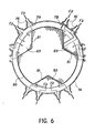
- a number of helium inlet tubes 76 (twelve in the embodiment shown in FIG. 6) are installed on this wall 74 and support small tube plates 78 on each of which are connected a certain number of tubes 72.
- These tubes 72 are then grouped together to descend along the exchange beam by a vertical straight part 72a.
- This straight part 72a extends to below the lower end of the external tubes 68. It is connected to the lower end of the external tubes 68 by a substantially horizontal part 72b, located below the lower end. tubes 68.
- This part 72b allows a certain differential expansion between the external tubes 68 and the helium inlet tubes 72.
- the circulation of helium in the steam generator is, represented schematically by arrows F 2 in Figure 3.
- the exchange structures of the steam generators 32 used in the reactor according to the invention therefore consist of a bundle of tubular cells Vertical elementary cells immersed in the Sodium Liquid 22 contained in the tank 10 of the reactor.
- the tubes 52, 58 and 68 constituting each tubular cell are independent of each other, in particular in terms of differential expansions between tubes and between the bundle and its outer envelope. This characteristic is fundamental for the mechanical reliability of the tubes and the steam generators as a whole.
- a chemically neutral intermediate fluid such as helium circulating between sodium and water / steam and at an intermediate temperature between that of these two fluids, it makes it possible to obtain steam generators with high mechanical integrity and reliability.
- this so-called dip tube structure makes it possible to obtain an acceptable thermal efficiency for an exchange height allowing the installation of the steam generators inside the reactor vessel.
- a 1500 MWe reactor with steam generators integrated in a main tank with an internal diameter less than or equal to 25 m and a height less than or equal to 18.5 m there is available for each generator an exchange height heat between 15 and 17 m and an outside diameter of the beam of about 1.75 m.
- the lengths of the tubes would be reduced if the internal tubes 58 included fins placed in the annular spaces 60 by which the water vapor rises.
- FIG. 3 shows a single elementary tubular cell, in increasing considerably The diameter of the tubes constituting this cell compared to the dimensions of the steam generator.
- FIG. 3 shows a very large number of elementary cells of the type which is shown in FIG. 3. These different cells define the actual exchange zone of the steam generator.
- the latter further comprises a ferrule 80 encircling the bundle of tubular ceLLuLes, this ferrule can for example be connected to the flared part 74 of the head of the steam generator.
- This ferrule 80 passes tightly through the internal vessel 26 of the reactor, for example by means of an argon bell sealing system 82.
- the entry of sodium contained in the hot collector 28 inside the ferrule 80 is effected by entry orifices 84 formed therein.
- these inlet ports 84 are located above the level N of sodium 22 in the reactor vessel, so that the level of sodium N 'inside the steam generator is greater than this level N
- the length of heat exchange between sodium and water in the water / steam circuit can thus be significantly increased, which, as mentioned above, allows the height of the reactor vessel to be limited to a reasonable value. .
- the use of finned helium-vapor tubes should make it possible to maintain the sodium entry level in the steam generator immediately below the main slab in order to ensure better thermal protection of the latter.
- the circulation of sodium from the hot collector 28 to the inlet orifices 84 takes place inside a collar 86 plunging into the so dium 22 and surrounding The ferrule 80 up to the inlet openings 84.
- the sodium outlet in the cold collector 30 takes place directly through the open lower end of the ferrule 80.
- the sodium circulation in the steam generator is represented schematically by arrows F 3 on Figure 3.
- the circulation of helium in the intermediate space 70 can make it possible to remove the residual heat dissipated in the reactor core, in the event of the primary pumps 34 being stopped (FIG. 1).
- the shutdown reactor exchangers that are usually used can thus be eliminated. So that a circulation of sodium 22 can be established by natural convection inside the virola 80, there is then provided on the latter, below the sodium level N, an entrance window 85 normally closed. The opening of this window is automatically controlled when the pumps 34 are stopped.
- calibrated windows allowing only a reduced flow of primary sodium at nominal speed can be offered.
- FIG. 3 schematically shows a first possible method of supporting the steam generator 32 in which it rests directly on the bottom of the vessel 10 of the reactor.
- This support which makes it possible not to overload the closing slab 12, is effected by means of a ferrule or feet 88 fixed to the lower end of the ferrule 80 and resting directly or indirectly on the bottom of the reactor vessel.
- the watertightness at the crossing of the slab 12 by the steam generator is then carried out for example using a bellows system 90, the ends of which are fixed respectively to the slab and to the collar 86.
- the upper part of the steam generator carrying the internal tubes 52 and intermediate 58 is removable in order to make it easier to control and inspect the external tubes 68 which are the only ones to be directly in contact with Primary sodium.
- the intermediate tube plate 54 extends outwardly beyond the wall 52, to form a flange 96 which rests on a flange 98 formed at the upper end of the wall 62.
- These two flanges are fixed to each other tightly by fixing means of any known type and in particular by bolts 100 passing through holes regularly distributed over the circumference of the flanges 96 and 98.
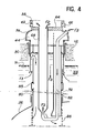
- FIG. 4 is a view comparable to FIG. 3 showing the size of the exchanger after removal of the removable upper part comprising the water inlet 40 and steam outlet 42 chambers, as well as the internal tubes 52 and intermediaries 58 associated with them. It can be seen in FIG. 4 that access to the external tubes 68 is thus completely released.
- This possibility of dismantling the steam generator also has the advantages of facilitating the manufacture of the generator in the factory, its transport, its assembly on site as well as subsequent checks or repairs.
- each of the tube plates is also made possible - by access orifices 41 43 and 45 formed respectively in the dome 46 and in the walls 51 and 62.
- the internal tube 52 has two coaxial walls 52a and 52b defining between them an annular zone 52c.
- this annular zone is closed at its upper end, at the level of the tube plate 48 and open at its lower end. It is therefore filled with water and stagnant steam, which provide satisfactory thermal insulation, especially in the upper part of the bundle in which such insulation is particularly necessary.
- the outer wall 52b of the inner tube 52 extends downward beyond its inner wall 52a, which allows the water reaching the lower end of the tubes to reduce its speed. This reduction in speed is favorable to the change of direction of the water which occurs in the bottom of the intermediate tubes 58.
- the internal tubes 52 also include an internal wall 52a and an external wall 52b separated by an annular zone 52c.
- this annular zone is closed in this case at the lower end of the inner tube 52a, which is also located above the lower end of the outer tube 52b.
- the zone 52c is open upwards at the level of the tube plate 48.
- the dome 46 of the steam generator is deleted and replaced by a cylindrical ferrule that 146 extending upwards the partition 51 and opening at its upper end in the reactor building.
- the zone 52c is therefore filled by a gas at atmospheric pressure and generally by the air which reigns above the steam generator.
- the ferrule 146 supports tube plates 151 to which the inlet pipes 150 are connected.
- the internal walls 52a of the internal tubes 52 extend above the upper tube plate 48, to be connected to the tube plates 151, a number of walls 52a being fixed on each of the plates.
- FIG. 5 a second variant of support for the steam generator has also been shown, in which it is suspended from the slab 12.
- the flared wall 74 has at its lower end a flange 92 which rests on a flange 94 fixed to slab 12 around the opening 38.
- the upper tube plate 48 is crossed by the internal tubes 52, of small diameter. It is at a moderate temperature corresponding to the temperature of the inlet supply water, i.e. about 260 ° C. Finally, it is subjected to an operating pressure corresponding to the pressure drop in the water / steam circuit. The thickness of this plate 48 is therefore moderate.
- the intermediate tube plate 54 is crossed by the intermediate tubes 58 which remain of modest size compared to the pitch of the network.
- This plate is subjected to an average operating pressure corresponding to the pressure difference between helium and vapor, for a moderate temperature of the order of 450 ° C. corresponding to the outlet temperature of the vapor. It is therefore slightly thicker than the tube plate 48.
- the lower tube plate 64 is the only one to be drilled to the diameter of the external tubes 68. It is subjected to temperature and pressure conditions close to those of the intermediate tube plate 54 (differential pressure of approximately 7 MPa and helium outlet temperature substantially below 500 ° C). In fact, it should be noted that the temperature of helium drops by about fifty degrees between the sodium level and the tube plate 64 due to the pursuit over almost three meters of the exchange of helium / vapor heat. . This phenomenon is very favorable to the behavior of the tube plate 64.
- the steam generator 32 used in the reactor according to the invention has a generally cylindrical configuration with a vertical axis.
- this layout is produced by providing inside the ferrule 80, of generally cylindrical configuration, three zones 83 for passage of the tubes 72 extending over the entire height of the ferrule, at 120 ° relative to each other.
- These zones 83 of substantially triangular section are delimited by the cylindrical shell 80 and by vertical partitions 81 having a V-shaped section. More precisely, the branches of the V formed in section by each of the partitions 81 are parallel with the adjacent branches of the other two partitions 81.
- the bundle of tubular cells thus presents in section The shape of a three-pointed star. It should be noted that this distribution of the tubes on the plates 48, 54 and 64 is favorable for dimensioning.
- the zones 83 in which they are housed the tubes 72 helium inflows are maintained in an atmosphere corresponding to those of the neutral gas overhead 24 of the reactor.
- This result is obtained by closing off the lower end of each of the zones 83 with a wall leaktightly crossed by the tubes-72.
- these zones 83 can be thermally insulated with respect to the interior of the ferrule 80 by means of appropriate thermal insulation systems (not shown).
- Another solution is to Leave. The sodium flows at reduced speed in these zones by heating the descending helium. These zones hardly differ from the other zones located in the sodium vat.
- the steam generator integrated into the reactor vessel in accordance with the invention therefore has a structure such that all the fluids descending into the main tank are contained in simple tubular structures taken separately, these structures being moderately stressed under well known and highly divided conditions, which considerably reduces the risks associated with cracks and possible leaks.
- a leak detection can be easily carried out, for example by monitoring the atmosphere of neutral gas which is in the steam generator, above the level N ′ of sodium, and in which the helium should result in source of leaks or in the reactor neutral gas sky.
- helium plays the role of thermal damper between these two fluids, which is an important point for reactors with fast neutrons.
- the water / steam circuit comprises a steam pipe 102 by laqueLLe
- the steam outlet pipe 56 of each of the steam generators 32 communicates with the high pressure stage 104a of a steam turbine 104 also comprising a medium pressure stage 104b and a low pressure stage 104c.
- the steam leaving the high pressure stage 104a via a pipe 105 passes through a dryer 106, a medium pressure reheater 108 by steam extraction and a reheater 110 by helium, before being directed to the medium pressure stage 104b of the turbine.
- the steam is directed to the low pressure stage 104c by a pipe 112, before being condensed in a condenser 35.
- the condensed water returns to the inlet pipes 50 of the steam generators 32 through a pipe 116.
- the reheater 110 through which the steam admitted into the medium pressure stage 104b of the turbine simultaneously cools the helium flowing in the intermediate circuit of the steam generators 32.
- the helium circuit consists of a pipe 118 which connects the helium outlet pipes 66 of the steam generators to the inlet of the reheater 110 and a return pipe 120 which connects The outlet of the reheater 110 to the helium inlet pipes 76 of the steam generators.
- the circulation of helium is controlled by a blower 122 placed in the return pipe 120.
- a treatment system 124 and in particular for drying the helium is mounted in parallel on the blower 122.
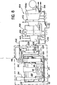
- FIG. 8 Another use of the heat transported by helium is proposed. It is represented in FIG. 8 where we notice a neutral gas circuit integrated in the reactor building and serving for additional heating of the feed water and for additional production of live steam.
- This circuit includes a water heater 126 and a complementary steam generator 128.
- helium in the intermediate circuit of steam generators is particularly interesting. In fact, this gas is chemically neutral and reacts neither with sodium nor with water. In addition, it does not require the use of steels different from those commonly used at operating temperatures. steam generator. Finally, it has good thermal and thermodynamic characteristics. In particular, its thermal conductivity is significantly higher than that of air or carbon dioxide, its specific heat is more than four times that of liquid sodium, but its specific mass is 120 to 150 times lower. Helium can be used on an industrial scale and its flow places little stress on structures. In addition, in the particular case according to the invention, in which the steam generator is integrated in the reactor vessel, it has the advantage of not absorbing the neutrons.
Abstract
L'invention concerne un réacteur nucléaire à neutrons rapides du type dans lequel le circuit primaire est intégré dans une cuve (10) remplie de métal liquide (22) et contenant le coeur (18) de réacteur. Les générateurs de vapeur (32) assurant l'échange thermique entre le métal liquide primaire (22) et le circuit eau vapeur sont également intégrés dans la cuve du réacteur. Ils comprennent des faisceaux de tubes droits verticaux imbriqués définissant entre eux des espaces intermédiaires dans lesquels on fait circuler un gaz chimiquement neutre tel que de l'hélium.The invention relates to a fast neutron nuclear reactor of the type in which the primary circuit is integrated in a vessel (10) filled with liquid metal (22) and containing the reactor core (18). The steam generators (32) ensuring the heat exchange between the primary liquid metal (22) and the steam water circuit are also integrated in the reactor vessel. They include bundles of nested vertical straight tubes defining between them intermediate spaces in which a chemically neutral gas such as helium is circulated.
Description
La présente invention se rapporte à un réacteur nucléaire à neutrons rapides du type comprenant un circuit primaire intégré dans une cuve remplie de métal Liquide et contenant Le coeur du réacteur ainsi que des pompes primaires pour faire circuler ce métal Liquide, et des moyens pour transférer La chaleur véhiculée par Le métal Liquide à L'eau circuLant dans un circuit eau/vapeur comportant des moyens pour transformer cette chaleur en électricité.The present invention relates to a fast neutron nuclear reactor of the type comprising a primary circuit integrated into a tank filled with liquid metal and containing the reactor core as well as primary pumps for circulating this liquid metal, and means for transferring the heat conveyed by the liquid metal to the water circulating in a water / vapor circuit comprising means for transforming this heat into electricity.
Dans Les réacteurs existants de ce type, tels que les réacteurs français Phénix et Super-Phénix, La chaleur véhiculée par Le métal Liquide du circuit primaire (généralement du sodium) est transférée à L'eau du circuit eau/vapeur par un circuit intermédiaire, dit circuit secondaire. Un métal Liquide (généraLement du sodium) circulant dans Le circuit secondaire prélève La chaleur véhiculée par Le métal Liquide primaire dans des échangeurs de chaleur intégrés à La cuve du réacteur, pour La transférer à L'eau du circuit eau/vapeur par des générateurs de vapeur externes à La cuve.In existing reactors of this type, such as the French Phoenix and Super-Phoenix reactors, the heat conveyed by the Liquid metal of the primary circuit (generally sodium) is transferred to the water of the water / vapor circuit by an intermediate circuit, said secondary circuit. A liquid metal (generally sodium) circulating in the secondary circuit takes the heat conveyed by the primary liquid metal in heat exchangers integrated in the reactor vessel, to transfer it to the water of the water / steam circuit by generators. Steam external to the tank.
Dans ces réacteurs, La présence du circuit secondaire de métal Liquide s'explique par Le désir d'éviter tout risque de venue en contact du sodium du circuit primaire avec L'eau du circuit eau/vapeur à L'intérieur même de La cuve du réacteur. En effet, on sait que La venue en contact du sodium avec de L'eau produit une réaction violente. Dans un réacteur nucléaire à neutrons rapides, un teL contact risque de se produire au niveau des générateurs de vapeur. Afin d'éviter que L'onde de choc résultant d'une éventuelle réaction sodium-eau ne se répercute jusqu'au coeur du réacteur, on a donc pris pour principe de placer Les générateurs de vapeur en dehors de La cuve du réacteur.In these reactors, the presence of the liquid metal secondary circuit is explained by the desire to avoid any risk of the sodium in the primary circuit coming into contact with the water in the water / steam circuit inside the tank of the reactor. Indeed, we know that the coming into contact of sodium with water produces a violent reaction. In a fast neutron nuclear reactor, such contact may occur at the steam generators. In order to prevent the shock wave resulting from a possible sodium-water reaction from passing through to the reactor core, it was therefore a principle to place the steam generators outside of the reactor vessel.
ParaLLèLement, Les réacteurs existants tels que Les réacteurs français Phénix et Super-Phénix sont des réacteurs de type intégré dans LesqueLs l'ensemble du circuit primaire se trouve confiné à L'intérieur de La cuve du réacteur. Cette option a été choisie pour tenir compte du fait qu'il est toujours préférable de confiner un circuit primaire radioactif à La fois pour des raisons de radioprotection et de sûreté.At the same time, existing reactors such as the French Phénix and Super-Phoenix reactors are reactors of the type integrated in which the entire primary circuit is confined inside the reactor vessel. This option was chosen to take into account the fact that it is always preferable to confine a radioactive primary circuit both for reasons of radiation protection and safety.
Compte tenu de ces deux impératifs opposés, Les réacteurs à neutrons rapides intégrés existants comprennent donc un circuit intermédiaire de métal Liquide. CeLa a évidemment pour conséquence d'en accroître Le coût de façon importante.Given these two opposite imperatives, the existing integrated fast neutron reactors therefore comprise an intermediate circuit of liquid metal. This obviously has the consequence of increasing the cost significantly.
Pour cette raison, on a déjà envisagé de supprimer Le circuit intermédiaire de métal Liquide en faisant sortir Le circuit primaire de La cuve du réacteur. Toutefois, cette solution n'est pas totalement satisfaisante, en raison de La forte radioactivité des produits de fission entraînés par Le métal Liquide primaire.For this reason, consideration has already been given to eliminating the intermediate circuit of liquid metal by removing the primary circuit from the vessel of the reactor. However, this solution is not entirely satisfactory, due to the high radioactivity of the fission products entrained by the primary liquid metal.
L'invention a précisément pour objet un réacteur nucléaire à neutrons rapides préservant L'intégration du circuit primaire à L'intérieur de La cuve du réacteur tout en permettant La suppression du circuit intermédiaire traditionnel de métal Liquide grâce à L'utiLisation de générateurs de vapeur d'un type nouveau pouvant être placés à L'intérieur de La cuve du réacteur sans qu'une réaction sodium/eau puisse se produire à ce niveau.The invention specifically relates to a fast neutron nuclear reactor preserving the integration of the primary circuit inside the reactor vessel while allowing the elimination of the traditional intermediate circuit of liquid metal through the use of steam generators. of a new type which can be placed inside the reactor vessel without a sodium / water reaction being able to take place at this level.
A cet effet, iL est proppsé conformément à L'invention un réacteur nucléaire à neutrons rapides du type comprenant un circuit primaire intégré dans une cuve remplie de métal Liquide et contenant Le coeur du réacteur ainsi que des moyens pour faire circuler ce métal Liquide et des moyens pour transférer La chaleur véhiculée par Le métal Liquide à L'eau circulant dans un circuit eau/vapeur, caractérisé en ce que Lesdits moyens de transfert de chaleur comprennent au moins un générateur de vapeur Logé dans La cuve du réacteur et comportant au moins un faisceau de tubes internes dans LesqueLs circule L'eau du circuit eau/vapeur, au moins un faisceau de tubes externes baignant dans Le métal Liquide primaire, Les tubes externes entourant chacun des tubes internes pour définir avec ceux-ci un espace annulaire sous pression de gaz neutre, relié à un circuit secondaire de faible puissance thermique comprenant des moyens pour faire circuler ce gaz neutre sous pression tel que de L'héLium dans Ledit espace annulaire et assurer L'échange thermique.To this end, iL is propped according to the invention a fast neutron nuclear reactor of the type comprising a primary circuit integrated in a tank filled with liquid metal and containing the reactor core as well as means for circulating this liquid metal and Ways to Transfer Heat conveyed by the Liquid metal to the water circulating in a water / steam circuit, characterized in that said heat transfer means comprise at least one steam generator housed in the reactor vessel and comprising at least one bundle of internal tubes in The water in the water / vapor circuit circulates, at least one bundle of external tubes immersed in the primary liquid metal, The external tubes surrounding each of the internal tubes to define with them an annular space under neutral gas pressure, connected to a secondary circuit of low thermal power comprising means for circulating this neutral gas under pressure such as helium in said annular space and ensuring heat exchange.
Grâce à ces caractéristiques, on intègre en réalité à L'intérieur de La cuve du réacteur des échangeurs métal Liquide-gaz neutre plutôt que des générateurs de vapeur au sens habituel du terme. Les exigences de sûreté sont ainsi préservées et Le coût d'investissement d'un tel réacteur est réduit de façon substantielle.Thanks to these characteristics, Liquid-gas-neutral metal heat exchangers are actually integrated inside the reactor vessel rather than steam generators in the usual sense of the term. The safety requirements are thus preserved and the investment cost of such a reactor is reduced substantially.
SeLon un mode de réalisation préféré de L'invention, La cuve du réacteur est obturée par une dalle de fermeture horizontale que traverse de façon étanche Le générateur de vapeur, ce dernier comportant au-dessus de La daLLe une plaque à tubes supérieure supportant Le faisceau de tubes internes, ouverts à Leur extrémité inférieure, une plaque à tubes intermédiaire surmontée par une chambre de sortie de vapeur du circuit eau/vapeur et supportant un faisceau de tubes intermédiaires entourant Les tubes internes, fermés à Leurs extrémités inférieures et dans Le, fond desquels débouchent Les tubes internes, et une plaque à tubes inférieure surmontée par une chambre de sortie de gaz neutre et supportant Le faisceau de tubes externes entourant Les tubes intermédiaires, Le générateur de vapeur comprenant de plus des tubes de gaz neutre reliant Le fond des tubes externes à des orifices d'entrée de gaz neutre situés entre La plaque à tubes inférieure et La dalle de fermeture.According to a preferred embodiment of the invention, the reactor vessel is closed off by a horizontal closing slab which the vapor generator passes through in a leaktight manner, the latter comprising an upper tube plate above the beam supporting the beam. of internal tubes, open at their lower end, an intermediate tube plate surmounted by a vapor outlet chamber of the water / steam circuit and supporting a bundle of intermediate tubes surrounding the internal tubes, closed at their lower ends and in the bottom from which the internal tubes open, and a lower tube plate surmounted by a neutral gas outlet chamber and supporting the bundle of external tubes in rotating the intermediate tubes, the steam generator further comprising neutral gas tubes connecting the bottom of the external tubes to neutral gas inlet orifices located between the lower tube plate and the closing slab.
Dans une telle structure, il est à noter que- tous Les tubes sont suspendus indépendamment Les uns des autres aux plaques à tubes correspondantes et Libres de se dilater vers Le bas. La fiabilité mécanique des tubes et du générateur de vapeur dans son ensemble s'en trouve améliorée.In such a structure, it should be noted that all the tubes are suspended independently of each other from the corresponding tube plates and free to expand downwards. This improves the mechanical reliability of the tubes and of the steam generator as a whole.
De même, bien que Les extrémités inférieures des tubes externes soient reliées à des tubes de gaz neutre, La dilatation de ces tubes externes est également rendue possible par Le fait que chacun des tubes de gaz neutre comporte de préférence une partie sensiblement horizontale de Longueur suffisante et de diamètre réduit donc à grande capacité de compensation de dilatation, située à La partie inférieure de L'appareil.Similarly, although the lower ends of the external tubes are connected to neutral gas tubes, the expansion of these external tubes is also made possible by the fact that each of the neutral gas tubes preferably comprises a substantially horizontal portion of sufficient length. and therefore reduced in diameter with a large expansion compensation capacity, located at the bottom of the device.
Conformément à L'invention, il faut également noter que l'enveLoppe habitueLLe des générateurs de vapeur disparaît pour être remplacée par une virole de confinement du métal Liquide de faible épaisseur. Cette virole, de conception très simple, est placée en-dessous de La plaque à tubes inférieure et encercle Les faisceaux de tubes internes, intermédiaires et externes imbriqués. Elle présente un orifice d'entrée du métal liquide situé au-dessus du niveau normal du métal Liquide dans La cuve du réacteur et elle est ouverte à son extrémité inférieure pour permettre La sortie du métal Liquide. Une hauteur d'échange satisfaisante peut ainsi être obtenue sans accroître La hauteur de La cuve du réacteur.In accordance with the invention, it should also be noted that the usual envelope of steam generators disappears and is replaced by a thin metal liquid confinement ring. This ferrule, of very simple design, is placed below the lower tube plate and encircles the bundles of nested internal, intermediate and external tubes. It has a liquid metal inlet port located above the normal level of the liquid metal in the reactor vessel and it is open at its lower end to allow the exit of the liquid metal. A satisfactory exchange height can thus be obtained without increasing the height of the reactor vessel.
En outre, L'intégration de générateurs de vapeur comportant un écoulement intermédiaire de gaz neutre à L'intérieur de La cuve du réacteur permet de supprimer Les échangeurs de refroidissement du réacteur à l'arrêt qui sont utilisés habituellement dans Les réacteurs intégrés. En effet, cette fonction de refroidissement du réacteur Lors de L'arrêt des pompes primaires peut être remplie par La partie échangeur métal Liquide-gaz neutre de chacun des générateurs de vapeur.In addition, the integration of generators Steam comprising an intermediate flow of neutral gas inside the reactor vessel makes it possible to eliminate the reactor-cooled cooling exchangers which are usually used in integrated reactors. In fact, this reactor cooling function When the primary pumps are stopped can be fulfilled by the liquid-neutral gas metal exchanger part of each of the steam generators.
Afin qu'une circulation du métal Liquide par convection naturelle puisse alors s'établir à L'intérieur de La virole en cas d'arrêt des pompes primaires, La virole présente de plus, en-dessous du niveau normal de métal Liquide dans La cuve du réacteur, des fenêtres d'entrée soit normalement obturées, des moyens commandant L'ouverture automatique de ces fenêtres Lors de l'arrêt des pompes primaires,soit calibrées de telle sorte qu'en régime nominal, elles ne Laissent passer qu'un débit réduit de sodium primaire.So that a circulation of the liquid metal by natural convection can then be established inside the shell in the event of the primary pumps stopping, the shell also presents, below the normal level of liquid metal in the tank of the reactor, inlet windows is normally closed, means controlling The automatic opening of these windows When the primary pumps are stopped, is calibrated so that in nominal mode, they only allow a flow reduced primary sodium.
De préférence, Le générateur de vapeur comporte une partie démontable comprenant La plaque à tubes supérieure, Le faisceau de tubes internes, La pLaque à tubes intermédiaire, La chambre de sortie de vapeur et Le faisceau de tubes intermédiaires. Cette disposition facilite La fabrication en usine, Le transport, Le montage sur Le site et surtout L'inspection en service, Les vérifications ou réparations ultérieures des tubes externes verticaux qui constituent Les tubes principaux des générateurs de vapeur.Preferably, the steam generator comprises a removable part comprising the upper tube plate, the internal tube bundle, the intermediate tube plate, the steam outlet chamber and the intermediate tube bundle. This arrangement facilitates factory production, transport, assembly on site and above all service inspection, subsequent checks or repairs to the vertical external tubes which constitute the main tubes of the steam generators.
Afin d'améliorer Le rendement thermique des générateurs de vapeur, chacun des tubes internes comporte de préférence deux parois coaxiales définissant entre elles une zone annulaire fermée à L'une de ses extrémités et remplie d'un fluide formant écran thermique.In order to improve the thermal efficiency of the steam generators, each of the internal tubes preferably comprises two coaxial walls defining between them an annular zone closed at one of its ends and filled with a fluid forming a heat shield.
SeLon une première variante de réalisation de l'invention, La pLaque à tubes supérieure est surmontée par une chambre d'entrée d'eau du circuit eau/vapeur. La zone annulaire formée entre Les parois de chacun des tubes internes est alors fermée à son extrémité supérieure, ouverte à son extrémité inférieure et remplie d'eau/vapeur stagnante donc à faible échange thermique.According to a first variant of the invention, the upper tube plate is surmounted by a water inlet chamber of the water / steam circuit. The annular zone formed between the walls of each of the internal tubes is then closed at its upper end, open at its lower end and filled with stagnant water / vapor therefore with low heat exchange.
SeLon une deuxième variante de réalisation de L'invention, La plaque à tubes supérieure forme Le fond supérieur du générateur de vapeur, Les parois internes des tubes internes se prolongeant au-dessus de La plaque à tubes supérieure pour déboucher dans des orifices d'entrée d'eau du circuit eau/vapeur. La zone annulaire formée entre Les parois de chacun des tubes internes est alors fermée à son extrémité inférieure, ouverte à son extrémité supérieure et remplie d'un gaz stagnant teL que de L'air surplombant La dalle du réacteur.According to a second variant embodiment of the invention, the upper tube plate forms the upper bottom of the steam generator, the internal walls of the internal tubes extending above the upper tube plate to open into inlet openings. water from the water / steam circuit. The annular zone formed between the walls of each of the internal tubes is then closed at its lower end, open at its upper end and filled with a stagnant gas such as air overhanging the reactor slab.
Afin de réduire La vitesse de L'eau dans Le bas de chaque tube interne avant qu'elle ne remonte dans L'espace intermédiaire correspondant, L'extrémité inférieure de La paroi interne de chacun des tubes internes est située au-dessus de l'extrémité inférieure de La paroi externe de chacun de ces tubes.In order to reduce the speed of the water at the bottom of each inner tube before it rises in the corresponding intermediate space, the lower end of the inner wall of each of the inner tubes is located above the lower end of the outer wall of each of these tubes.
Le circuit eau/vapeur comprenant de façon habitueLLe une turbine à vapeur, Le circuit secondaire comprend de préférence un resurchauffeur assurant un transfert de La chaleur véhiculée par Le gaz neutre de ce circuit vers La vapeur à resurchauffer avant que celle-ci ne soit admise dans La partie correspondante de La turbine.The water / steam circuit usually comprising a steam turbine, The secondary circuit preferably comprises a reheater ensuring a transfer of the heat conveyed by the neutral gas of this circuit to the steam to be reheated before it is admitted into The corresponding part of the turbine.
En variante, on peut envisager un circuit secondaire de gaz neutre confiné à L'intérieur du bâtiment réacteur. Dans ce cas La quantité de chaleur emportée hors du générateur de vapeur principal peut être utilisée par exemple, pour un complément de production de vapeur vive et pour un complément de rechauffage de L'eau d'alimentation.As a variant, it is possible to envisage a secondary neutral gas circuit confined to the interior of the reactor building. In this case The quantity of heat taken out of the main steam generator can be used for example, for additional steam production lively and for additional heating of the feed water.
On décrira maintenant, à titre d'exemple non Limitatif, un mode de réalisation préféré de L'invention en se référant aux dessins annexés dans LesqueLs :
- - La figure 1 est une vue en coupe transversale représentant de façon schématique un réacteur nucléaire à neutrons rapides comportant des générateurs de vapeur intégrés à La cuve conformément à L'invention,
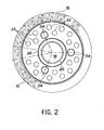
- - La figure 2 est une vue en plan, en coupe selon La Ligne II-II de La figure 1,
- - La figure 3 est une vue en coupe Longitudinale schématique d'un générateur de vapeur du réacteur représenté sur Les figures 1 et 2, montrant à une échelle volontairement agrandie pour en faciliter La Lecture L'une des cellules tubulaires élémentaires du générateur,
- - La figure 4 est une vue comparabLe à La figure 3 représentant Le générateur de vapeur après enlèvement de La partie eau/vapeur démontable de celui-ci,
- - La figure 5 est une vue comparable à La figure 3 iLLustrant une variante de réalisation du générateur de vapeur pouvant être utilisé dans le réacteur selon L'invention,
- - La figure 6 est une vue en coupe transversale du générateur de vapeur selon La Ligne VI-VI de La figure 3, et
- - La figure 7 est une vue schématique représentant Le circuit de gaz neutre et Le circuit eau/vapeur du réacteur selon L'invention,
- - La figure 8 est une vue schématique comparable à La figure 7, représentant une variante dans LaqueLLe Le circuit de gaz neutre est disposé à L'intérieur du bâtiment réacteur.
- FIG. 1 is a cross-sectional view schematically representing a fast neutron nuclear reactor comprising steam generators integrated in the tank in accordance with the invention,
- FIG. 2 is a plan view, in section along line II-II of FIG. 1,
- FIG. 3 is a schematic longitudinal section view of a steam generator of the reactor shown in FIGS. 1 and 2, showing on a voluntarily enlarged scale to facilitate reading One of the elementary tubular cells of the generator,
- FIG. 4 is a view comparable to FIG. 3 representing the steam generator after removal of the removable water / steam part thereof,
- FIG. 5 is a view comparable to FIG. 3 illustrating an alternative embodiment of the steam generator which can be used in the reactor according to the invention,
- FIG. 6 is a cross-sectional view of the steam generator along line VI-VI of FIG. 3, and
- FIG. 7 is a schematic view showing the neutral gas circuit and the water / steam circuit of the reactor according to the invention,
- - Figure 8 is a schematic view comparable to Figure 7, showing a variant in LaqueLLe The neutral gas circuit is arranged inside the reactor building.
On a représenté schématiquement sur La figure 1 le circuit primaire intégré d'un réacteur nucléaire à neutrons rapides réalisé conformément à l'invention.FIG. 1 schematically shows the integrated primary circuit of a fast neutron nuclear reactor produced in accordance with the invention.
De façon en soi connue pour un réacteur nucléaire à neutrons rapides de type intégré, on voit sur La figure 1 que l'ensemble du circuit primaire du réacteur selon L'invention est placé à L'intérieur d'une cuve cylindrique 10, d'axe vertical, dite cuve principale, obturée à son extrémité supérieure par une dalle de fermeture 12 remplie de béton. La cuve principale 10 et sa dalle de fermeture 12 sont placées dans un puits de cuve 14 formé dans une enceinte de béton 16. De façon connue, Le supportage de La cuve 10 peut se faire soit en posant celle-ci sur Le fond du puits de cuve 14, soit en suspendant La cuve à La partie supérieure du puits de cuve, comme l'illustre La figure 1.In a manner known per se for an integrated type fast neutron nuclear reactor, it can be seen in FIG. 1 that the entire primary circuit of the reactor according to the invention is placed inside a
Le coeur 18 du réacteur est placé à L'intérieur de La cuve 10, dans La partie centrale de celle-ci et repose sur Le fond de La cuve 10 par L'intermédiaire d'une structure de supportage comportant un sommier 20 servant par ailleurs à l'alimentation du coeur en sodium Liquide.The
La cuve 10 est remplie jusqu'à un niveau N d'un certain volume de métal Liquide 22, généralement constitué par du sodium. Le sodium 22 est surmonté par un ciel de gaz neutre 24 généralement constitué par de L'argon. Une cuve interne 26, par exemple à redan, définit à L'intérieur de La cuve principale 10 un coLLecteur chaud 28 situé au-dessus du coeur 18 et de La cuve 26 et un collecteur froid annulaire 30 entourant Le coeur 18.The
Conformément à L'invention, un certain nombre de générateurs de vapeur 32 traversent La dalle de fermeture 12 et plongent dans La partie périphérique de La cuve principale 10, en traversant La cuve interne 26. Le sodium chaud sortant du coeur 18 du réacteur et admis dans Le collecteur chaud 28 pénètre dans Les générateurs de vapeur 32. En traversant ces derniers, il se refroidit par échange thermique avec L'eau du circuit eau/vapeur, avant de ressortir dans Le collecteur froid 30. De façon connue, Le réacteur comprend de plus un certain nombre de pompes primaires 34 placées à L'intérieur du collecteur froid 30. Ces pompes primaires 34 aspirent Le sodium primaire relativement froid rejeté dans Le collecteur 30 par Les générateurs de vapeur 32, pour Le refouler dans Le sommier 20 d'alimentation du coeur 18 du réacteur par des conduites 36.According to the invention, a certain number of
Comme L'iLLustre notamment La figure 2, Le circuit primaire qui vient d'être décrit en se référant à La figure 1 peut comprendre trois pompes primaires 34, six générateurs de vapeur étant associés à chacune de ces pompes. Toutefois, cette réalisation n'est évidemment pas Limitative et un nombre différent de pompes et de générateurs de vapeur peut être envisagé.As illustrated in particular in FIG. 2, the primary circuit which has just been described with reference to FIG. 1 may include three
Comme dans Les réacteurs intégrés existants, Le supportage des composants situés à L'intérieur de La cuve du réacteur, c'est-à-dire ici Le supportage des générateurs de vapeur 32 et des pompes 34, peut être réalisé soit par une suspension de ces composants à La dalle de fermeture 12,-soit en faisant reposer ces composants sur Le fond de La cuve 10, comme on L'a représenté schématiquement sur La figure 1.As in the existing integrated reactors, the support of the components located inside the reactor vessel, that is to say here the support of the
On décrira maintenant en se référant à La figure 3 un mode de réalisation préféré du générateur de vapeur 32.A preferred embodiment of the
Ainsi, on voit sur La figure 3 que Le générateur de vapeur 32 présente une configuration généralement verticale et traverse un passage 38 formé dans La dalle 12, de telle sorte que La zone d'échange proprement dite plonge directement dans Le sodium 22 contenu dans La cuve du réacteur, alors que Le raccordement du générateur de vapeur au circuit eau/vapeur du réacteur et à un circuit secondâire de gaz neutre est réalisé par une partie du générateur située au-dessus de La dalle 12.Thus, it can be seen in FIG. 3 that the
Cette partie du générateur de vapeur située au-dessus de La dalle 12, qui constitue La tête de ce composant, comprend en partant du haut une chambre d'entrée d'eau 40, une chambre de sortie de vapeur 42 et une chambre de sortie d'hélium 44 dans L'exempLe considéré où l'hélium constitue Le gaz chimiquement neutre qui assure Le transfert de chaleur entre Le sodium primaire et L'eau du circuit eau/vapeur. Ce gaz chimiquement neutre peut toutefois être un gaz différent et même un mélange de gaz.This part of the steam generator located above the
La chambre d'entrée d'eau 40 est formée entre Le dôme supérieur 46 du générateur de vapeur et une plaque à tubes horizontale supérieure 48. Le dôme 46 porte une tubulure d'entrée d'eau 50 servant à raccorder La chambre 40 au circuit eau/vapeur comme on Le verra ultérieurement.The
La plaque à tubes supérieure 48 supporte un faisceau de tubes droits verticaux 52, ouverts à Leurs extrémités inférieures et s'étendant Librement vers Le bas à partir de La plaque 48 jusqu'à L'intérieur de La cuve du réacteur.The
La chambre de sortie de vapeur 42 est formée quant à elle à L'intérieur d'une paroi cylindrique 51 prolongeant vers Le bas Le dôme 46, entre La plaque à tubes supérieure 48 et une plaque à tubes horizontale intermédiaire 54. Une tubulure de sortie de vapeur 56 est prévue dans La paroi 51 pour permettre Le raccordement de La chambre de sortie de vapeur 42 avec Le circuit eau/vapeur.The
La plaque à tubes intermédiaire 54 supporte un faisceau de tubes droits verticaux 58 dits tubes intermédiaires, qui sont disposés de façon coaxiale autour de chacun des tubes internes 52, de façon à définir avec ces derniers des passages annulaires 60.The
Comme Le montre La figure 3, Les tubes intermédiaires 58 sont fermés à Leurs extrémités inférieures, à proximité de LaqueLLe débouchent Les tubes internes 52. Une circulation de L'eau, puis de La vapeur s'établit ainsi depuis La chambre d'entrée d'eau 40 jusqu'à La chambre de sortie de vapeur 42. Ainsi, L'eau admise dans La chambre 40 descend à L'intérieur des tubes internes 52, avant de remonter par Les espaces annulaires 60 jusqu'à La chambre de sortie de vapeur 42, comme l'illustrent Les flèches F1 sur La figure 3.As shown in Figure 3, the
La chambre de sortie d'hélium 44 est également formée à L'intérieur d'une paroi cylindrique 62 disposée dans Le prolongement de La paroi 51, et elle est délimitée entre La plaque à tubes intermédiaire 54 et une plaque à tubes inférieure horizontale 64. Une tubulure de sortie 66 formée dans La paroi 62 permet de raccorder La chambre de sortie d'hélium 44 au circuit d'hélium qui sera décrit ultérieurement.The
La plaque à tubes inférieure 64 supporte un troisième faisceau de tubes droits verticaux 68 disposé coaxiaLement autour de chacun des tubes intermédiaires 58, de façon à définir avec ces derniers une deuxième série d'espaces annulaires 70.The
Comme Le montre La figure 3, Les tubes externes 68 se prolongent vers Le bas Légèrement au-delà du fond des tubes intermédiaires 58, de façon à être raccordés à des tubes d'arrivée d'hélium 72 de diamètre réduit servant à introduire l'hélium par Le bas de chacun des tubes 68, de teLLe sorte que ce gaz neutre remonte par Les espaces annulaires 70 jusque dans La chambre de sortie d'hélium 44.As shown in Figure 3, the
Bien qu'on puisse envisager en théorie d'introduire l'hélium par des tubes 72 traversant de préférence Le fond de La cuve du réacteur, La solution La plus réaliste représentée sur La figure 3 consiste à faire remonter Les tubes 72, en dehors du faisceau d'échange proprement dit, jusqu'au-dessus de La dalle 12 pour assurer L'indépendance du générateur par rapport à La cuve principale.Although one could consider in theory to introduce helium by
En pratique, on voit sur La figure 3 que Le générateur de vapeur comporte à cet effet une zone élargie délimitée par une paroi évasée 74 qui s'étend vers Le bas depuis La plaque à tubes inférieure 64 jusqu'à proximité de La face supérieure de La daLLe de fermeture 12. Un certain nombre de tubulures d'entrée d'hélium 76 (douze dans Le mode de réalisation représenté sur La figure 6) sont implantées sur cette paroi 74 et supportent des petites plaques à tubes 78 sur chacune desquelles sont raccordés un certain nombre de tubes 72. Ces tubes 72 sont ensuite regroupés pour descendre Le Long du faisceau d'échange par une partie droite verticale 72a. Cette partie droite 72a se proLonge jusqu'en-dessous de L'extrémité inférieure des tubes externes 68. ELLe est raccordée à L'extrémité inférieure des tubes externes 68 par une partie sensiblement horizontale 72b, située en-dessous de l'extrémité, inférieure des tubes 68. Cette partie 72b autorise une certaine dilatation différentielle entre Les tubes externes 68 et Les tubes d'arrivée d'hélium 72. La circuLa-tion de l'hélium dans l,e générateur de vapeur est, représentée schématiquement par des flèches F2 sur La figure 3.In practice, it can be seen in FIG. 3 that the steam generator has for this purpose an enlarged zone delimited by a flared
Les structures d'échange des générateurs de vapeur 32 utilisés dans Le réacteur selon L'invention sont donc constituées par un faisceau de cellules tubuLaires élémentaires verticales plongeant dans Le sodium Liquide 22 contenu dans La cuve 10 du réacteur. Dans cette structure, Les tubes 52, 58 et 68 constituant chaque cellule tubulaire sont indépendants Les uns des autres, notamment sur Le plan des dilatations différentielles entre tubes et entre Le faisceau et son enveLoppe extérieure. Cette caractéristique est fondamentale pour La fiabilité mécanique des tubes et des générateurs de vapeur dans leur ensemble. Associée à L'utiLisation d'un fluide intermédiaire chimiquement neutre tel que L'héLium en circulation entre Le sodium et L'eau/vapeur et à une température intermédiaire entre celle de ces deux fluides, elle permet d'obtenir des générateurs de vapeur à intégrité mécanique et à fiabiLité élevées.The exchange structures of the
De plus, cette structure dite à tubes plongeurs permet d'obtenir un rendement thermique acceptabLe pour une hauteur d'échange autorisant l'implantation des générateurs de vapeur à L'intérieur de La cuve du réacteur. Ainsi, pour un réacteur de 1500 MWe à générateurs de vapeur intégrés dans une cuve principale de diamètre intérieur inférieur ou égal à 25 m et de hauteur inférieure ou égale à 18,5 m, on dispose pour chaque générateur d'une hauteur d'échange de chaleur comprise entre 15 et 17 m et d'un diamètre extérieur du faisceau d'environ 1,75m. Les Longueurs de tubes seraient réduites si Les tubes internes 58 comportaient des aiLettes placées dans Les espaces annulaires 60 par Lesquels remonte La vapeur d'eau.In addition, this so-called dip tube structure makes it possible to obtain an acceptable thermal efficiency for an exchange height allowing the installation of the steam generators inside the reactor vessel. Thus, for a 1500 MWe reactor with steam generators integrated in a main tank with an internal diameter less than or equal to 25 m and a height less than or equal to 18.5 m, there is available for each generator an exchange height heat between 15 and 17 m and an outside diameter of the beam of about 1.75 m. The lengths of the tubes would be reduced if the
Afin de permettre une bonne compréhension de La structure du générateur de vapeur utilisé dans Le réacteur selon L'invention et notamment afin que Les circulations des différents fluides dans Les tubes apparaissent clairement, on a représenté sur La figure 3 une seule cellule tubulaire élémentaire, en accroissant considérablement Le diamètre des tubes constituant cette cellule par rapport aux dimensions du générateur de vapeur. En pratique, il existe bien entendu un très grand nombre de cellules élémentaires du type de celle qui est représentée sur La figure 3. Ces différentes cellules définissent La zone d'échange proprement dite du générateur de vapeur.In order to allow a good understanding of the structure of the steam generator used in the reactor according to the invention and in particular so that the circulations of the various fluids in the tubes appear clearly, FIG. 3 shows a single elementary tubular cell, in increasing considerably The diameter of the tubes constituting this cell compared to the dimensions of the steam generator. In practice, there are of course a very large number of elementary cells of the type which is shown in FIG. 3. These different cells define the actual exchange zone of the steam generator.
Afin de canaliser l'écoulement du sodium 22 autour des différentes cellules tubulaires du générateur de vapeur, celui-ci comprend de plus une virole 80 encerclant Le faisceau de ceLLuLes tubulaires, cette virole pouvant par exemple être raccordée à La partie évasée 74 de La tête du générateur de vapeur. Cette virole 80 traverse de façon étanche La cuve interne 26 du réacteur, par exemple par L'intermédiaire d'un système d'étanchéité à cloche d'argon 82.In order to channel the flow of
L'entrée du sodium contenu dans Le collecteur chaud 28 à L'intérieur de La virole 80 s'effectue par des orifices d'entrée 84 formés dans celle-ci. De préférence, ces orifices d'entrée 84 sont situés au-dessus du niveau N du sodium 22 dans La cuve du réacteur, de telle sorte que Le niveau de sodium N' à L'intérieur du générateur de vapeur soit supérieur à ce niveau N. On peut ainsi accroître notablement La Longueur d'échange thermique entre Le sodium et L'eau du circuit eau/vapeur, ce qui permet, comme on L'a mentionné précédemment, de Limiter à une valeur raisonnable La hauteur de La cuve du réacteur. L'utiLisation de tubes vapeur- hélium à ailettes devrait permettre de maintenir Le niveau d'entrée du sodium dans Le générateur de vapeur immédiatement en-dessous de La dalle principale en vue d'assurer une meilleure protection thermique de cette dernière. La circulation du sodium depuis Le collecteur chaud 28 jusqu'aux orifices d'entrée 84 s'effectue à L'intérieur d'une collerette 86 plongeant dans Le sodium 22 et entourant La virole 80 jusqu'au-dessus des orifices d'entrée 84.The entry of sodium contained in the
En partie basse du générateur de vapeur, La sortie du sodium dans Le collecteur froid 30 s'effectue directement par L'extrémité inférieure ouverte de La virole 80. La circulation du sodium dans Le générateur de vapeur est représentée schématiquement par des fLèches F3 sur La figure 3.In the lower part of the steam generator, the sodium outlet in the
En outre, La circulation de l'hélium dans L'espace intermédiaire 70 peut permettre d'évacuer La chaleur résiduelle dissipée dans Le coeur du réacteur, en cas d'arrêt des pompes primaires 34 (figure 1). Les échangeurs de refroidissement du réacteur à L'arrêt qui sont utilisés habituellement peuvent ainsi être supprimés. Afin qu'une circulation du sodium 22 puisse s'établir par convection naturelle à L'intérieur de La viroLe 80, on prévoit alors sur cette dernière, en-dessous du niveau N du sodium une fenêtre d'entrée 85 normalement fermée. L'ouverture de cette fenêtre est commandée automatiquement Lors de L'arrêt des pompes 34. En variante, des fenêtres calibrées ne Laissant passer qu'un débit réduit de sodium primaire en régime nominal, peuvent être proposées.In addition, the circulation of helium in the
On a représenté schématiquement sur La figure 3 un premier mode de supportage possible du générateur de vapeur 32 dans LequeL celui-ci repose directement sur Le fond de La cuve 10 du réacteur. Ce supportage qui permet de ne pas surcharger La dalle de fermeture 12, s'effectue grâce à une virole ou à des pieds 88 fixés à L'extrémité inférieure de La virole 80 et reposant directement ou indirectement sur Le fond de La cuve du réacteur. Pour tenir compte de La dilatation différentieLLe, L'étanchéité au niveau de La traversée de La dalle 12 par Le générateur de vapeur est alors réalisée par exemple à L'aide d'un système à soufflet 90 dont Les extrémités sont fixées respectivement à La dalle et à La collerette 86.FIG. 3 schematically shows a first possible method of supporting the
De préférence et comme L'iLLustre également La figure 3, La partie supérieure du générateur de vapeur portant Les tubes internes 52 et intermédiaires 58 est démontable afin de rendre plus aisé un contrôle et une inspection des tubes externes 68 qui sont Les seuls à être directement en contact avec Le sodium primaire. A cet effet, La plaque à tubes intermédiaire 54 se proLonge vers L'extérieur au-delà de La paroi 52, pour former une bride 96 qui repose sur une bride 98 formée à L'extrémité supérieure de La paroi 62. Ces deux brides sont fixées L'une sur L'autre de façon étanche par des moyens de fixation de tout type connu et notamment par des boulons 100 traversant des trous régulièrement répartis sur La circonférence des brides 96 et 98.Preferably and as illustrated also in FIG. 3, the upper part of the steam generator carrying the
La figure 4 est une vue comparable à La figure 3 montrant L'aLLure de L'échangeur après enlèvement de La partie supérieure démontable comprenant Les chambres d'entrée d'eau 40 et de sortie de vapeur 42, ainsi que Les tubes internes 52 et intermédiaires 58 qui Leur sont associés. On voit sur La figure 4 que L'accès aux tubes externes 68 est ainsi totalement Libéré.FIG. 4 is a view comparable to FIG. 3 showing the size of the exchanger after removal of the removable upper part comprising the
Cette possibilité de démontage du générateur de vapeur a par ailleurs pour avantages de faciliter La fabrication du générateur en usine, son transport, son montage sur Le site ainsi que Les vérifications ou réparations ultérieures.This possibility of dismantling the steam generator also has the advantages of facilitating the manufacture of the generator in the factory, its transport, its assembly on site as well as subsequent checks or repairs.
Par ailleurs, une inspection de chacune des plaques à tubes est également rendue possible- par des orifices d'accès 41 43 et 45 formés respectivement dans Le dôme 46 et dans Les parois 51 et 62.Furthermore, an inspection of each of the tube plates is also made possible - by access orifices 41 43 and 45 formed respectively in the
On a mentionné précédemment que L'eau du circuit eau/vapeur descend par Les tubes internes 52 avant de remonter dans Les espaces annulaires 60 définis autour de ces tubes. IL risque donc de se produire un échange de chaleur parasite entre L'eau relativement froide pénétrant par Les tubes internes 52, et La vapeur remontant par Les espaces 60.It was previously mentioned that the water in the water / vapor circuit descends through the
Afin de réduire fortement cet échange de chaLeur parasite, Le tube interne 52 comporte deux parois coaxiales 52a et 52b définissant entre elles une zone annulaire 52c. Dans Le mode de réalisation représenté sur La figure 3, cette zone annulaire est obturée à son extrémité supérieure, au niveau de La plaque à tubes 48 et ouverte à son extrémité inférieure. Elle est donc remplie d'eau et de vapeur stagnante, qui assurent une isolation thermique satisfaisante, surtout dans La partie supérieure du faisceau dans LaqueLLe une telle isoLation est particulièrement nécessaire.In order to greatly reduce this exchange of parasitic heat, the
Dans Le mode de réalisation préféré représenté sur La figure 3, La paroi externe 52b du tube interne 52 se prolonge vers Le bas au-delà de sa paroi interne 52a, ce qui permet à L'eau parvenant à L'extrémité inférieure des tubes de réduire sa vitesse. Cette réduction de vitesse est favorable au changement de direction de L'eau qui se produit dans Le fond des tubes intermédiaires 58.In the preferred embodiment shown in Figure 3, the
Dans une autre variante de réalisation de L'invention représentée sur La figure 5, Les tubes internes 52 comprennent également une paroi interne 52a et une paroi externe 52b séparées par une zone annulaire 52c. Toutefois, cette zone annulaire est obturée dans ce cas au niveau de L'extrémité inférieure du tube interne 52a, qui se trouve également située au-dessus de L'extrémité inférieure du tube externe 52b. Au contraire, La zone 52c est ouverte vers Le haut au niveau de La plaque à tubes 48.In another alternative embodiment of the invention shown in FIG. 5, the
Dans ce cas, Le dôme 46 du générateur de vapeur est supprimé et remplacé par une virole cylindrique 146 prolongeant vers Le haut La cloison 51 et s'ouvrant à son extrémité supérieure dans Le bâtiment du réacteur. La zone 52c est donc remplie par un gaz à La pression atmosphérique et généralement par L'air qui règne au-dessus du générateur de vapeur. La virole 146 supporte des plaques à tubes 151 sur LesqueLLes sont raccordées Les tubulures d'entrée 150. Les parois internes 52a des tubes internes 52 se prolongent au-dessus de La plaque à tubes supérieure 48, pour être raccordées aux plaques à tubes 151, un certain nombre de parois 52a étant fixées sur chacune des plaques.In this case, the
Sur La figure 5, on a également représenté une deuxième variante de supportage du générateur de vapeur, dans LaqueLLe celui-ci est suspendu à La dalle 12. Dans ce cas, La paroi évasée 74 comporte à son extrémité inférieure une bride 92 qui repose sur une bride 94 fixée à La dalle 12 autour de L'ouverture 38.In FIG. 5, a second variant of support for the steam generator has also been shown, in which it is suspended from the
En pratique et bien que cela ne soit pas représenté sur Les figures, il est souhaitable de prévoir un centrage des tubes internes 52 à L'intérieur des tubes intermédiaires 58, ainsi qu'un centrage de ces derniers à L'intérieur des tubes externes 68. Ce centrage peut être réalisé à L'aide de tout moyen approprié connu et notamment grâce à des dispositifs en héLice fixés à L'extérieur des tubes 52 et 58, au moins dans La partie basse de ceux-ci, autorisant l'écoulement vers Le haut de La vapeur et de l'hélium, et améLiorant L'échange thermique.In practice and although this is not shown in the figures, it is desirable to provide a centering of the
En ce qui concerne Le dimensionnement des plaques à tubes 48, 54 et 64, Les remarques suivantes peuvent être faites.With regard to the dimensioning of the
La plaque à tubes supérieure 48 est traversée par Les tubes internes 52, de faible diamètre. Elle se trouve à une température modérée correspondant à La température de L'eau d'alimentation à L'entrée, soit environ 260°C. Enfin, elle est soumise à une pression de service correspondant à La perte de charge du circuit eau/vapeur. L'épaisseur de cette plaque 48 est donc modérée.The
La plaque à tubes intermédiaire 54 est traversée par Les tubes intermédiaires 58 qui restent de dimension modeste par rapport au pas du réseau. Cette plaque est soumise à une pression de service moyenne correspondant à La différence de pression entre l'héLium et La vapeur, pour une température modérée de L'ordre de 450°C correspondant à La température de sortie de La vapeur. Elle est donc Légèrement plus épaisse que La plaque à tubes 48.The
Enfin, La plaque à tubes inférieure 64 est La seule à être percée au diamètre des tubes externes 68. ELle est soumise à des conditions de température et de pression voisines de celles de La plaque à tubes intermédiaire 54 (pression différentielle d'environ 7 MPa et température de sortie d'hélium sensiblement inférieure à 500°C). En effet, iL faut noter que La température de L'héLium baisse d'une cinquantaine de degrés entre Le niveau de sodium et La plaque à tubes 64 en raison de La poursuite sur près de trois mètres de L'échange de chaLeur héLium/vapeur. Ce phénomène est très favorable au comportement de La plaque à tubes 64.Finally, the
On a déjà mentionné que Le générateur de vapeur 32 utilisé dans Le réacteur selon L'invention présente une configuration généralement cylindrique d'axe vertical. En pratique on comprend toutefois à La Lecture de La description qui précède, que se pose Le problème de l'implantation des parties verticales 72a des tubes 72 d'arrivée d'hélium par rapport à L'ensembLe des ceLLuLes tubulaires du générateur. Dans une configuration préférentielle bien que non Limitative représentée sur La figure 6, cette implantation est réalisée en ménageant à l'intérieur de La virole 80, de configuration'généralement cylindrique, trois zones 83 de passage des tubes 72 s'étendant sur toute La hauteur de La virole, à 120° Les unes par rapport aux autres. Ces zones 83 de section sensiblement triangulaire, sont délimitées par La virole cylindrique 80 et par des cloisons verticales 81 présentant une section en forme de V. De façon plus précise, Les branches des V formés en section par chacune des cloisons 81 sont paraLLèLes avec Les branches adjacentes des deux autres cloisons 81.It has already been mentioned that the
Le faisceau de cellules tubulaires présente ainsi en section La forme d'une étoile à trois branches. IL est à noter que cette répartition des tubes sur Les plaques 48, 54 et 64 est favorable au dimensionnement.The bundle of tubular cells thus presents in section The shape of a three-pointed star. It should be noted that this distribution of the tubes on the
De préférence, afin d'éviter un échange de chaleur parasite entre Le sodium chaud rentrant à La partie supérieure de La virole 80 et Le sodium refroidi sortant à L'extrémité inférieure de celle-ci, Les zones 83 dans LesqueLLes sont Logés Les tubes 72 d'arrivée d'hélium sont maintenues en atmosphère correspondant à celles du ciel de gaz neutre 24 du réacteur. Ce résultat est obtenu en obturant L'extrémité inférieure de chacune des zones 83 par une paroi traversée de façon étanche par Les tubes-72. De ptus, ces zones 83 peuvent être isolées thermiquement par rapport à L'intérieur de La virole 80 grâce à des systèmes de calorifugeage appropriés (non représentés). Une autre solution consiste à Laisser. Le sodium s'écouler à vitesse réduite dans ces zones en réchauffant l'hélium descendant. Ces zones ne ce différencient guère des autres zones situées dans La cuve de sodium.Preferably, in order to avoid a parasitic heat exchange between the hot sodium entering the upper part of the
Le générateur de vapeur intégré à La cuve de réacteur conformément à L'invention présente donc une structure telle que tous Les fluides descendant dans La cuve principale sont contenus dans des structures tubuLaires simples prises séparément, ces structures étant modérément sollicitées dans des conditions bien connues et fortement divisées, ce qui réduit de façon considérabLe Les risques Liés à des fissures et à des fuites éventuelles. De plus, une détection de fuite peut être réalisée aisément, par exemple en contrôlant L'atmosphère de gaz neutre qui se trouve dans Le générateur de vapeur, au-dessus du niveau N' de sodium, et dans Laquelle devrait aboutir l'hélium en provenance des fuites ou dans Le ciel de gaz neutre du réacteur.The steam generator integrated into the reactor vessel in accordance with the invention therefore has a structure such that all the fluids descending into the main tank are contained in simple tubular structures taken separately, these structures being moderately stressed under well known and highly divided conditions, which considerably reduces the risks associated with cracks and possible leaks. In addition, a leak detection can be easily carried out, for example by monitoring the atmosphere of neutral gas which is in the steam generator, above the level N ′ of sodium, and in which the helium should result in source of leaks or in the reactor neutral gas sky.
Par ailleurs, en plus de ses fonctions de transfert de chaleur et de milieu intermédiaire entre Le sodium et l'eau vapeur, L'héLium joue Le rôle d'amortisseur thermique entre ces deux fluides, ce qui est un point important pour Les réacteurs à neutrons rapides.Furthermore, in addition to its functions of heat transfer and intermediate medium between sodium and steam, helium plays the role of thermal damper between these two fluids, which is an important point for reactors with fast neutrons.
Sur La figure 7, on a représenté de façon schématique et à titre d'exemple non Limitatif L'ensembLe des circuits eau/vapeur et hélium du réacteur selon L'invention.In Figure 7, there is shown schematically and by way of nonlimiting example the whole of the water / vapor and helium circuits of the reactor according to the invention.
Le circuit eau/vapeur comprend une conduite 102 de vapeur par LaqueLLe La tubulure de sortie de vapeur 56 de chacun des générateurs de vapeur 32 communique avec L'étage haute pression 104a d'une turbine à vapeur 104 comportant par ailleurs un étage moyenne pression 104b et un étage basse pression 104c. La vapeur sortant de L'étage haute pression 104a par une tuyauterie 105 traverse un sécheur 106, un resurchauffeur moyenne pression 108 par soutirage vapeur et un resurchauffeur 110 par hélium, avant d'être dirigée vers L'étage moyenne pression 104b de La turbine. Enfin, La vapeur est dirigée vers L'étage basse pression 104c par une conduite 112, avant d'être condensée dans un condenseur 35.The water / steam circuit comprises a
L'eau de condensation retourne aux tubulures d'entrée 50 des générateurs de vapeur 32 par une canaLisation 116.The condensed water returns to the
Conformément à une caractéristique intéressante de L'invention, Le resurchauffeur 110 que traverse La vapeur admise dans L'étage moyenne pression 104b de La turbine assure simultanément Le refroidissement de l'hélium circulant dans Le circuit intermédiaire des générateurs de vapeur 32. A cet effet, on voit sur La figure 7 que Le circuit d'hélium se compose d'une canaLisation 118 qui relie Les tubulures de sortie d'hélium 66 des générateurs de vapeur à L'entrée du resurchauffeur 110 et d'une canalisation retour 120 qui relie La sortie du resurchauffeur 110 aux tubulures d'entrée d'hélium 76 des générateurs de vapeur. La circulation de l'hélium est commandée par une soufflante 122 placée dans La canalisation retour 120. Un système de traitement 124 et notamment de séchage de l'hélium est monté en paraLLèLe sur La soufflante 122.In accordance with an advantageous characteristic of the invention, the
Conformément à une variante de La disposition précédente, une autre utilisation de La chaleur transportée par l'hélium est proposée. Elle est représentée sur La figure 8 ou L'on remarque un circuit de gaz neutre intégré dans Le bâtiment réacteur et servant à un réchauffage complémentaire de L'eau d'alimentation et à une production complémentaire de vapeur vive. Ce circuit comprend un réchauffeur d'eau 126 et un générateur de vapeur complémentaire 128.In accordance with a variant of the preceding arrangement, another use of the heat transported by helium is proposed. It is represented in FIG. 8 where we notice a neutral gas circuit integrated in the reactor building and serving for additional heating of the feed water and for additional production of live steam. This circuit includes a
L'utilisation d'hélium dans Le circuit intermédiaire des générateurs de vapeur est particulièrement intéressante. En effet, ce gaz est chimiquement neutre et ne réagit ni avec Le sodium ni avec L'eau. De plus, il n'exige pas L'empLoi d'aciers différents de ceux couramment utilisés aux températures de fonctionnement élevées d'un générateur de vapeur. Enfin, il possède de bonnes caractéristiques thermiques et thermodynamiques. En particulier, sa conductibilité thermique est sensiblement plus élevée que celle de L'air ou du gaz carbonique, sa chaleur spécifique est plus de quatre fois supérieure à ceLLe du sodium liquide, mais sa masse spécifique est de 120 à 150 fois plus faible. L'héLium est utilisable à échelle industrielle et son écoulement sollicite peu Les structures. De plus, dans Le cas particulier selon L'invention, dans LequeL le générateur de vapeur est intégré dans La cuve du réacteur, il présente L'avantage de ne pas absorber Les neutrons.The use of helium in the intermediate circuit of steam generators is particularly interesting. In fact, this gas is chemically neutral and reacts neither with sodium nor with water. In addition, it does not require the use of steels different from those commonly used at operating temperatures. steam generator. Finally, it has good thermal and thermodynamic characteristics. In particular, its thermal conductivity is significantly higher than that of air or carbon dioxide, its specific heat is more than four times that of liquid sodium, but its specific mass is 120 to 150 times lower. Helium can be used on an industrial scale and its flow places little stress on structures. In addition, in the particular case according to the invention, in which the steam generator is integrated in the reactor vessel, it has the advantage of not absorbing the neutrons.
Claims (15)
Applications Claiming Priority (2)
| Application Number | Priority Date | Filing Date | Title |
|---|---|---|---|
| FR8407332 | 1984-05-11 | ||
| FR8407332A FR2564229B1 (en) | 1984-05-11 | 1984-05-11 | FAST NEUTRAL NUCLEAR REACTOR WITH INTEGRATED VAPOR GENERATOR |
Publications (2)
| Publication Number | Publication Date |
|---|---|
| EP0163564A1 true EP0163564A1 (en) | 1985-12-04 |
| EP0163564B1 EP0163564B1 (en) | 1988-07-27 |
Family
ID=9303897
Family Applications (1)
| Application Number | Title | Priority Date | Filing Date |
|---|---|---|---|
| EP85400878A Expired EP0163564B1 (en) | 1984-05-11 | 1985-05-06 | Fast neutron nuclear reactor with a steam generator integrated in the vessel |
Country Status (5)
| Country | Link |
|---|---|
| US (1) | US4705662A (en) |
| EP (1) | EP0163564B1 (en) |
| JP (1) | JPS60244891A (en) |
| DE (1) | DE3564054D1 (en) |
| FR (1) | FR2564229B1 (en) |
Cited By (6)
| Publication number | Priority date | Publication date | Assignee | Title |
|---|---|---|---|---|
| EP0228722A2 (en) * | 1985-12-26 | 1987-07-15 | Stone & Webster Engineering Corporation | Double tube steam generator |
| FR2595459A1 (en) * | 1986-03-07 | 1987-09-11 | Trepaud Echangeurs | Gas-layer heat exchanger |
| EP0362155A2 (en) * | 1988-09-27 | 1990-04-04 | ANSALDO S.p.A. | Intermediate exchanger of a fast reactor, equipped with a raised upper tube plate, intake siphon and emergency input window |
| FR2995628A1 (en) * | 2012-09-19 | 2014-03-21 | Alstom Technology Ltd | STEAM ENERGY CONVERSION CYCLE PRODUCED BY A SODIUM-COOLED QUICK-SOURCE REACTOR |
| CN107679272A (en) * | 2017-08-28 | 2018-02-09 | 中国船舶重工集团公司第七〇九研究所 | Vertical steam generator U-tube flows backwards the heat-transfer pipe group technology in state simulation |
| FR3079959A1 (en) * | 2018-04-09 | 2019-10-11 | Didier Costes | COOLED SODIUM COOLED REACTOR, GAS HEATING FOR TURBO-ALTERNATOR WITHOUT INTERMEDIATE CIRCUIT |
Families Citing this family (5)
| Publication number | Priority date | Publication date | Assignee | Title |
|---|---|---|---|---|
| FR2626709B1 (en) * | 1988-01-29 | 1992-12-31 | Novatome | INTERMEDIATE HEAT EXCHANGER OF A FAST NEUTRAL NUCLEAR REACTOR |
| US7139352B2 (en) * | 1999-12-28 | 2006-11-21 | Kabushiki Kaisha Toshiba | Reactivity control rod for core |
| ITMI20051752A1 (en) * | 2005-09-21 | 2007-03-22 | Ansaldo Energia Spa | NUCLEAR REACTOR IN PARTICULAR LIQUID METAL COOLED NUCLEAR REACTOR |
| JP2008122248A (en) * | 2006-11-13 | 2008-05-29 | Toshiba Corp | Fast reactor |
| US20120307956A1 (en) | 2010-02-05 | 2012-12-06 | Singh Krishna P | Nuclear reactor system having natural circulation of primary coolant |
Citations (4)
| Publication number | Priority date | Publication date | Assignee | Title |
|---|---|---|---|---|
| FR2015805A1 (en) * | 1968-08-16 | 1970-04-30 | Combustion Eng | |
| FR2055476A5 (en) * | 1969-07-22 | 1971-05-07 | Wheeler Foster Corp | |
| DE2400882A1 (en) * | 1973-02-26 | 1974-08-29 | Combustion Eng | SLEEVE AND PIPE HEAT EXCHANGER |
| FR2228194A1 (en) * | 1973-02-16 | 1974-11-29 | Hitachi Ltd |
Family Cites Families (5)
| Publication number | Priority date | Publication date | Assignee | Title |
|---|---|---|---|---|
| JPS5139319B2 (en) * | 1972-03-31 | 1976-10-27 | ||
| US4140176A (en) * | 1973-03-26 | 1979-02-20 | The United States Of America As Represented By The United States Department Of Energy | Protective tubes for sodium heated water tubes |
| US3907026A (en) * | 1973-08-21 | 1975-09-23 | Westinghouse Electric Corp | Double tube heat exchanger |
| US3999602A (en) * | 1975-10-21 | 1976-12-28 | The United States Of America As Represented By The United States Energy Research And Development Administration | Matrix heat exchanger including a liquid, thermal couplant |
| US4560533A (en) * | 1984-08-30 | 1985-12-24 | The United States Of America As Represented By The United States Department Of Energy | Fast reactor power plant design having heat pipe heat exchanger |
-
1984
- 1984-05-11 FR FR8407332A patent/FR2564229B1/en not_active Expired
-
1985
- 1985-05-06 DE DE8585400878T patent/DE3564054D1/en not_active Expired
- 1985-05-06 EP EP85400878A patent/EP0163564B1/en not_active Expired
- 1985-05-10 US US06/732,742 patent/US4705662A/en not_active Expired - Fee Related
- 1985-05-10 JP JP60098137A patent/JPS60244891A/en active Pending
Patent Citations (4)
| Publication number | Priority date | Publication date | Assignee | Title |
|---|---|---|---|---|
| FR2015805A1 (en) * | 1968-08-16 | 1970-04-30 | Combustion Eng | |
| FR2055476A5 (en) * | 1969-07-22 | 1971-05-07 | Wheeler Foster Corp | |
| FR2228194A1 (en) * | 1973-02-16 | 1974-11-29 | Hitachi Ltd | |
| DE2400882A1 (en) * | 1973-02-26 | 1974-08-29 | Combustion Eng | SLEEVE AND PIPE HEAT EXCHANGER |
Cited By (11)
| Publication number | Priority date | Publication date | Assignee | Title |
|---|---|---|---|---|
| EP0228722A2 (en) * | 1985-12-26 | 1987-07-15 | Stone & Webster Engineering Corporation | Double tube steam generator |
| EP0228722A3 (en) * | 1985-12-26 | 1988-10-26 | Stone & Webster Engineering Corporation | Double tube steam generator |
| FR2595459A1 (en) * | 1986-03-07 | 1987-09-11 | Trepaud Echangeurs | Gas-layer heat exchanger |
| EP0362155A2 (en) * | 1988-09-27 | 1990-04-04 | ANSALDO S.p.A. | Intermediate exchanger of a fast reactor, equipped with a raised upper tube plate, intake siphon and emergency input window |
| EP0362155A3 (en) * | 1988-09-27 | 1990-08-22 | ANSALDO S.p.A. | Intermediate exchanger of a fast reactor, equipped with a raised upper tube plate, intake siphon and emergency input window |
| FR2995628A1 (en) * | 2012-09-19 | 2014-03-21 | Alstom Technology Ltd | STEAM ENERGY CONVERSION CYCLE PRODUCED BY A SODIUM-COOLED QUICK-SOURCE REACTOR |
| EP2711508A1 (en) * | 2012-09-19 | 2014-03-26 | Alstom Technology Ltd | Energy conversion cycle for the steam produced by a sodium-cooled fast neutron reactor |
| RU2561839C2 (en) * | 2012-09-19 | 2015-09-10 | Альстом Текнолоджи Лтд | Energy conversion cycle for steam generated by fast neutron reactor with sodium cooling |
| CN107679272A (en) * | 2017-08-28 | 2018-02-09 | 中国船舶重工集团公司第七〇九研究所 | Vertical steam generator U-tube flows backwards the heat-transfer pipe group technology in state simulation |
| CN107679272B (en) * | 2017-08-28 | 2021-01-08 | 中国船舶重工集团公司第七一九研究所 | Heat transfer pipe grouping method in backflow state simulation of U-shaped pipe of vertical steam generator |
| FR3079959A1 (en) * | 2018-04-09 | 2019-10-11 | Didier Costes | COOLED SODIUM COOLED REACTOR, GAS HEATING FOR TURBO-ALTERNATOR WITHOUT INTERMEDIATE CIRCUIT |
Also Published As
| Publication number | Publication date |
|---|---|
| FR2564229A1 (en) | 1985-11-15 |
| DE3564054D1 (en) | 1988-09-01 |
| JPS60244891A (en) | 1985-12-04 |
| EP0163564B1 (en) | 1988-07-27 |
| FR2564229B1 (en) | 1986-09-05 |
| US4705662A (en) | 1987-11-10 |
Similar Documents
| Publication | Publication Date | Title |
|---|---|---|
| EP0163564B1 (en) | Fast neutron nuclear reactor with a steam generator integrated in the vessel | |
| EP0147304B1 (en) | Sodium-water steam generator with concentric straight tubes and gas circulation in the annular space | |
| EP0246969B1 (en) | Small pressurized-water nuclear reactor with natural circulation | |
| EP0068913A1 (en) | Fast breeder reactor with a residual heat dissipation system | |
| EP0055643B1 (en) | Nuclear reactor cooled by a liquid metal contained in a vessel closed by upper closures | |
| EP0083545B1 (en) | Device for emergency evacuation of the heat produced by a fast neutron nuclear reactor at standstill | |
| EP0105781B1 (en) | Secondary thermal carrier circuit for a liquid metal-cooled nuclear reactor, and steam generator for such a circuit | |
| EP0153225A2 (en) | Heat-exchanger with emergency cooling arrangements and fast nuclear reactor having such a heat-exchanger | |
| EP0258131B1 (en) | Emergency cooling arrangement for fast neutron reactor | |
| EP0020264B1 (en) | Semi-modular type heat exchanger for nuclear reactor | |
| FR2584227A1 (en) | DEVICE FOR CONDENSING A PRESSURIZED WATER VAPOR AND ITS APPLICATION TO THE COOLING OF A NUCLEAR REACTOR AFTER AN INCIDENT. | |
| EP0055963A2 (en) | Liquid metal cooled nuclear reactor comprising a main vessel cooled at the bottom | |
| EP0108690B1 (en) | Heat exchanger for high temperature fluids in which one of the fluids enters and leaves by way of the superior part of the exchanger | |
| EP0018262A1 (en) | Fast neutron nuclear reactor with an internal cylindrical vessel | |
| EP0064920B1 (en) | Apparatus for steam generation and heat exchange in a fast breeder reactor | |
| EP0117191A1 (en) | Steam generator for a liquid metal-cooled nuclear reactor | |
| EP0173602A1 (en) | Emergency heat exchanger for cooling the primary fluid of a nuclear reactor, and method of assembling this heat exchanger | |
| EP0206921B1 (en) | Heat exchanger with coaxial u-tubes and intermediate circulation of neutral gas, and fast neutron reactor comprising such a heat exchanger | |
| FR2555794A1 (en) | Fast-neutron nuclear reactor fitted with emergency cooling means | |
| EP0047698B1 (en) | Mixed convection cooling by the primary fluid in a nuclear reactor | |
| FR2713752A1 (en) | Heat exchanger using intermediate fluid in divided vessel | |
| EP0064921A1 (en) | Cooling system for the main vessel of a fast breeder reactor | |
| EP0216667B1 (en) | Apparatus to retain liquid in a substantially horizontal conduit, open at one end, when the liquid flow rate drops below a given level | |
| FR2518707A1 (en) | DEVICE FOR PRODUCING STEAM BY EXCHANGING HEAT BETWEEN A LIQUID-COOLED METAL AND FOOD WATER | |
| EP0144256A1 (en) | Thermal protection device for a fast neutrons nuclear reactor component |
Legal Events
| Date | Code | Title | Description |
|---|---|---|---|
| PUAI | Public reference made under article 153(3) epc to a published international application that has entered the european phase |
Free format text: ORIGINAL CODE: 0009012 |
|
| AK | Designated contracting states |
Designated state(s): BE DE GB IT NL |
|
| 17P | Request for examination filed |
Effective date: 19860509 |
|
| 17Q | First examination report despatched |
Effective date: 19870714 |
|
| RAP1 | Party data changed (applicant data changed or rights of an application transferred) |
Owner name: COMMISSARIAT A L'ENERGIE ATOMIQUE |
|
| GRAA | (expected) grant |
Free format text: ORIGINAL CODE: 0009210 |
|
| AK | Designated contracting states |
Kind code of ref document: B1 Designated state(s): BE DE GB IT NL |
|
| GBT | Gb: translation of ep patent filed (gb section 77(6)(a)/1977) | ||
| REF | Corresponds to: |
Ref document number: 3564054 Country of ref document: DE Date of ref document: 19880901 |
|
| ITF | It: translation for a ep patent filed |
Owner name: JACOBACCI & PERANI S.P.A. |
|
| PGFP | Annual fee paid to national office [announced via postgrant information from national office to epo] |
Ref country code: DE Payment date: 19890429 Year of fee payment: 5 |
|
| PGFP | Annual fee paid to national office [announced via postgrant information from national office to epo] |
Ref country code: BE Payment date: 19890502 Year of fee payment: 5 |
|
| PLBE | No opposition filed within time limit |
Free format text: ORIGINAL CODE: 0009261 |
|
| STAA | Information on the status of an ep patent application or granted ep patent |
Free format text: STATUS: NO OPPOSITION FILED WITHIN TIME LIMIT |
|
| ITTA | It: last paid annual fee | ||
| PGFP | Annual fee paid to national office [announced via postgrant information from national office to epo] |
Ref country code: NL Payment date: 19890531 Year of fee payment: 5 Ref country code: GB Payment date: 19890531 Year of fee payment: 5 |
|
| 26N | No opposition filed | ||
| PG25 | Lapsed in a contracting state [announced via postgrant information from national office to epo] |
Ref country code: GB Effective date: 19900506 |
|
| PG25 | Lapsed in a contracting state [announced via postgrant information from national office to epo] |
Ref country code: BE Effective date: 19900531 |
|
| BERE | Be: lapsed |
Owner name: COMMISSARIAT A L'ENERGIE ATOMIQUE Effective date: 19900531 |
|
| PG25 | Lapsed in a contracting state [announced via postgrant information from national office to epo] |
Ref country code: NL Effective date: 19901201 |
|
| GBPC | Gb: european patent ceased through non-payment of renewal fee | ||
| NLV4 | Nl: lapsed or anulled due to non-payment of the annual fee | ||
| PG25 | Lapsed in a contracting state [announced via postgrant information from national office to epo] |
Ref country code: DE Effective date: 19910201 |