EP0162952B1 - Switching bridge for electrical switching devices, particularly for contactors - Google Patents
Switching bridge for electrical switching devices, particularly for contactors Download PDFInfo
- Publication number
- EP0162952B1 EP0162952B1 EP84112789A EP84112789A EP0162952B1 EP 0162952 B1 EP0162952 B1 EP 0162952B1 EP 84112789 A EP84112789 A EP 84112789A EP 84112789 A EP84112789 A EP 84112789A EP 0162952 B1 EP0162952 B1 EP 0162952B1
- Authority
- EP
- European Patent Office
- Prior art keywords
- contact
- window
- connecting bridge
- bridge
- frame
- Prior art date
- Legal status (The legal status is an assumption and is not a legal conclusion. Google has not performed a legal analysis and makes no representation as to the accuracy of the status listed.)
- Expired
Links
- 229910052751 metal Inorganic materials 0.000 claims description 6
- 239000002184 metal Substances 0.000 claims description 6
- 239000004020 conductor Substances 0.000 claims description 3
- 229910052709 silver Inorganic materials 0.000 claims description 2
- 239000004332 silver Substances 0.000 claims description 2
- 238000005299 abrasion Methods 0.000 description 6
- 238000004519 manufacturing process Methods 0.000 description 4
- 239000000463 material Substances 0.000 description 3
- 238000010276 construction Methods 0.000 description 2
- 239000012858 resilient material Substances 0.000 description 2
- BQCADISMDOOEFD-UHFFFAOYSA-N Silver Chemical compound [Ag] BQCADISMDOOEFD-UHFFFAOYSA-N 0.000 description 1
- 238000004140 cleaning Methods 0.000 description 1
- 230000006835 compression Effects 0.000 description 1
- 238000007906 compression Methods 0.000 description 1
- 230000001419 dependent effect Effects 0.000 description 1
- 238000010586 diagram Methods 0.000 description 1
- 230000000694 effects Effects 0.000 description 1
- 230000001771 impaired effect Effects 0.000 description 1
- 230000002035 prolonged effect Effects 0.000 description 1
- 230000003014 reinforcing effect Effects 0.000 description 1
- 230000000630 rising effect Effects 0.000 description 1
- 238000005096 rolling process Methods 0.000 description 1
- 238000007493 shaping process Methods 0.000 description 1
- 239000007787 solid Substances 0.000 description 1
- 239000000725 suspension Substances 0.000 description 1
Images


Classifications
-
- H—ELECTRICITY
- H01—ELECTRIC ELEMENTS
- H01H—ELECTRIC SWITCHES; RELAYS; SELECTORS; EMERGENCY PROTECTIVE DEVICES
- H01H1/00—Contacts
- H01H1/12—Contacts characterised by the manner in which co-operating contacts engage
- H01H1/14—Contacts characterised by the manner in which co-operating contacts engage by abutting
- H01H1/20—Bridging contacts
- H01H1/2025—Bridging contacts comprising two-parallel bridges
Definitions
- the invention relates to a switching bridge for electrical switching devices, in particular for contactors, with a number of contact bridges which are arranged next to and / or one above the other in windows and which carry contact pieces at their ends and which are each under the pressure of a contact spring.
- Switching bridges of the aforementioned type are known, for example, from DE-A-1 909 460 in a wide variety of embodiments. What these switching bridges have in common, however, is that all the contact springs are designed as spiral springs and are inserted into the respective windows in such a way that they are supported either on the upper or lower wall of the window and on the other hand on the relevant contact bridge.
- This construction has the disadvantage that only manual manufacture of the switching bridge is possible, i.e. that each contact bridge with the associated spiral contact spring must be inserted by hand into the window in question.
- Another disadvantage is that the coil spring only presses in the middle on the contact bridge in question and cannot cause the contact bridge to be held.
- each contact bridge seen in its longitudinal direction, must be provided with projections or other guide pieces on both sides, which usually grip around the edges of the window and in this way keep the contact bridge immovable in its longitudinal direction.
- projections or other guide pieces on both sides, which usually grip around the edges of the window and in this way keep the contact bridge immovable in its longitudinal direction.
- a switching bridge for electrical switching devices is known from DE-C-1 071 198, in which a contact bridge which is movably arranged in a window is under the pressure of a leaf spring bent convexly to the contact bridge, the ends of which are bent concavely.
- This leaf spring has a locking point in the central area, which interacts positively with a closure piece of the window.
- the contact bridge is held transversely by the side walls of the window.
- the purpose of this design is to enable the switching bridge to be replaced if it is provided with bent-up arcing horns.
- a head is arranged at the upper end of a plunger.
- the window is formed by a slot, which is worked in, starting from the upper face of the head, so that two side cheeks remain.
- a locking piece engages in these cheeks, which is attached above the switching bridge used.
- the locking piece is secured by a cylinder piece which is attached to the front end of the head by a bayonet lock. In this way, the bridge can be removed from the slot after loosening the cylinder piece and the closure piece. Automatic assembly of the contact bridges is not possible or intended here.
- a leaf spring arrangement for the external suspension and mounting of a freely movable contact bridge for electrical switches is known.
- a movable contact bridge rests on an insulating base and can be moved up and down along a guide bar that is firmly attached to the base.
- the guide bar extends through a central rectangular opening in the contact bridge.
- On the guide bar sits an oval to kidney-like bent leaf spring, the ends of the contact bridge are held in recesses in the guide bar.
- the invention has for its object to provide a switching bridge, which is once an automatic production, i.e. Equipped with contact bridges, in which abrasion is practically avoided and which ensures high contact reliability.
- each contact spring is designed as a convexly curved leaf spring to the associated contact bridge, that the contact spring has a locking point in the central region, which interacts positively with the adjacent window wall, that the ends of the contact spring and the ends of the contact bridge are bent so concavely and cooperate with one another that the contact bridge is held in the longitudinal direction by the contact spring and in the transverse direction by the side walls of the window, and that the contact spring has a longitudinal slot to the ends on both sides of the locking point, so that both Resilient arms are created on each slot.
- each contact bridge can be grasped mechanically together with an overlying leaf spring. With a slight compression of the leaf spring, it can then be easily pushed into the window with the contact bridge without tilting or the like being necessary. If the leaf spring is now released, the locking point of the contact spring engages positively on the adjacent window wall, so that the contact spring and the contact bridge are held securely at the same time.
- the contact reliability is significantly increased by the fact that resilient arms are formed on both sides of the longitudinal slots and the contact spring at four points on the contact bridge presses.
- each contact bridge is bent from a resilient, electrically conductive material in the form of a frame, so that a two-fold current-conducting connection between the contact pieces and the frame forms the contact pressure springs, and that the frame has on each side of the window a longitudinal slit to the ends, so that resilient arms are formed on both sides of the slit.
- the contact spring is bent in a C-shape and its ends are each supported on a folded part of the contact bridge, and that the contact spring has a longitudinal slot running to the ends on both sides of the locking point , so that resilient arms are formed on both sides of the respective slot.
- this design gives the further advantage of a particularly secure mounting and guiding of the contact bridge and, in turn, great contact security.
- Figures 1 to 3 show a partial section of a switching bridge 1 with a transverse window 2.
- the switching bridge can have any number of windows one above the other and / or next to each other, so that the construction described below is repeated correspondingly often for each window.
- 1, recesses 3 and 4 are provided on both sides of the window, so that the actual window is provided in the web 5.
- the remaining ones in the edge of the switching bridge, which protrude beyond the web 5, can be designed as reinforcing ribs.
- a projection 6 is formed, which is expediently rectangular, as illustrated in FIG. 2. This projection engages in an opening 7 of a contact spring 8 and holds it in every operating position, and also in a manner that prevents it from rotating. As illustrated in FIG.
- the contact spring 8 is designed as a leaf spring bent convexly with respect to the associated contact bridge 11 located underneath.
- the ends 9 and 10 of the contact or leaf spring 8 on both sides and the ends 12 and 13 of the contact bridge 11 are somewhat upwards according to FIG. bent concave.
- the ends are under spring pressure and act in such a way that the contact bridge 11 is held in the longitudinal direction by the contact spring 8.
- the contact bridge 11 is held in the transverse direction by the side walls of the window 2.
- the contact bridge 11 has rectilinear longitudinal edges, that is to say essentially consists of a rectangular, well-conducting metal strip. With this arrangement and mounting, the contact bridge practically does not come into frictional contact with the side walls of the window 2 or the further side surfaces of the switching bridge 1, so that no abrasion can form.
- the contact bridge 11 is solid and has contact pieces 14 and 15 on the underside.
- the contact spring 8 is provided with two longitudinal slots 18 which run to the ends and which merge into a rounding 19 on the inside.
- Resilient arms 16 and 17 are formed on both sides of the slot 18, as can be seen in FIG. 2 for the left part of the contact spring 8.
- FIGS. 1 to 3 illustrate one another exemplary embodiment, to which the above statements also apply mutatis mutandis.
- the parts corresponding to the exemplary embodiment according to FIGS. 1 to 3 are therefore not described again and provided with reference numerals.
- the contact bridge 20 is somewhat thinner, saves on material and weight.
- the contact bridge 20 is also provided with two longitudinal slots 33 which run to the ends, so that a total of four arms 21, 22, 23 and 24 which run in pairs parallel to one another are formed on both sides of these longitudinal slots.
- Each of these arms carries a contact piece 29, 30, 31 and 32. This is a measure which leads to a further improvement in the contact security.
- the concavely bent ends of the contact spring 34 again work with the likewise concavely bent ends 25, 26, 27 and 28 of the above-described arms 21 to 24.
- the latching point of the contact spring designed as a leaf spring is an opening 7 into which the projection 6 engages.
- This transverse rib can be arched downward, so that a projection engaging in the transverse rib produces a positive connection or holder from above.
- the cross rib can also be curved upwards. This can then engage or rest in a notch in the adjacent window wall.
- FIGS. 7 and 8 show a further preferred exemplary embodiment of a switching bridge according to the invention.
- the contact bridge consists of a resiliently elastic or self-resilient material, namely an electrically thin, relatively thin metal strip.
- the contact bridge is bent in the form of a frame 35, as is particularly clear from FIG. 7.
- the frame 35 consists of a lower, uninterrupted part 36, on the underside of which the contact pieces 48, 49 and 50, 51 (FIG. 8) are fastened. With rounded corners, this frame part 36 is followed by frame parts 37 and 38 leading upwards, which in turn merge with rounded corners into the upper frame parts 39 and 40 pointing inwards.
- the frame 35 is thus essentially rectangular, but the frame parts 39 and 40 rise somewhat obliquely inward in the rest position according to the drawn position according to FIG. 7.
- the contact pieces 48 to 51 are, as indicated, arranged on the outside of the uninterrupted part 36 of the frame, namely towards the ends of this part.
- the frame can consist of an uninterrupted metal strip, for example by being cut from a tube and then being deformed. For manufacturing reasons, however, it is expedient to punch the contact bridge out of a flat metal strip and then to deform it into an essentially rectangular frame. In this case, it is useful to bend the ends 41 and 42 of the metal strip in the central region of the window 2 of the switching bridge 1 and to carry out the shaping in such a way that these ends lie close together.
- the ends 41 and 42 are advantageously provided with a silver layer on the surfaces lying against one another, so that a good current transfer is ensured. Because the contact bridge is designed as a frame 35, a double current-conducting connection between the contact pieces 48 and 49 on the one hand and the contact pieces 50 and 51 on the other hand is present.
- the self-resilient or resilient material is selected so that the frame 35 forms the contact pressure springs at the same time.
- the ends 41 and 42 of the frame members 39 and 40 are inward, i.e. bent downward in Fig. 7 essentially by 90 °.
- a recess 43, z. B. provided in a rectangular shape.
- a projection 6 engages in these two cutouts, which protrudes into the window 2 as shown.
- the frame part 39 is first pressed downward by the projection 6 until the correct position is reached and the projection 6 engages in the recesses 43 and secures the position of the frame.
- parts 44 and 45 bent downwards can also be provided on the inner edges of the cutouts 43.
- the frame 35 is provided with slots 46 and 47 in the areas on both sides of the window 2, and the four contact pieces 48 to 51 described are accordingly attached.
- Figure 7 also shows that on both sides of the window 2 slightly inclined outwardly rising contact surfaces 52 and 53 are formed on the switching bridge 1.
- the frame parts 39 and 40 can be supported on these contact surfaces 52 and 53.
- the frame parts 39 and 40 perform a certain pivoting movement between the rest position and the operating position, like a comparison of the drawn position with the Operating position shows.
- the bent ends 41 and 42 perform a certain rolling movement with respect to one another, so that a self-cleaning effect occurs on the abutting surfaces described and a good current transfer is always guaranteed.
- the contact spring 67 is bent in a C-shape.
- the inwardly facing ends 68 and 69 of the contact spring 67 are each supported on a folded part 77 and 79 or 78 of the contact bridge 75.
- the contact bridge 75 again carries contact pieces 71, 72, 73 and 74 on the underside.
- both the contact spring 67 and the contact bridge 75 have longitudinal slots 70 and 76 (FIG. 10).
Landscapes
- Push-Button Switches (AREA)
- Tumbler Switches (AREA)
- Contacts (AREA)
Description
Die Erfindung bezieht sich auf eine Schaltbrücke für elektrische Schaltgeräte, insbesondere für Schütze, mit einer Anzahl neben-und/oder übereinander in Fenstern beweglich angeordneter Kontaktbrücken, welche an ihren Enden Kontaktstücke tragen und welche unter dem Druck je einer Kontaktfeder stehen.The invention relates to a switching bridge for electrical switching devices, in particular for contactors, with a number of contact bridges which are arranged next to and / or one above the other in windows and which carry contact pieces at their ends and which are each under the pressure of a contact spring.
Schaltbrücken der vorbezeichneten Gattung sind beispielweise aus der DE-A-1 909 460 in den verschiedensten Ausführungsformen bekannt. Gemeinsam ist diesen Schaltbrücken aber, daß sämtliche Kontaktfedern als Spiralfedern ausgebildet und derart in die jeweiligen Fenster eingesetzt sind, daß sie sich einerseits entweder an der oberen oder unteren Wand des Fensters und andererseits an der betreffenden Kontaktbrücke abstützen. Diese Konstruktion bringt den Nachteil mit sich, daß nur eine manuelle Fertigung der Schaltbrücke möglich ist, d.h. daß jede Kontaktbrücke mit der dazu gehörigen spiralförmigen Kontaktfeder von Hand in das betreffende Fenster eingesetzt werden muß. Ein weiterer Nachteil besteht darin, daß die Spiralfeder nur in der Mitte auf die betreffende Kontaktbrücke drückt und keine Halterung der Kontaktbrücke bewirken kann. Daher muß jede Kontaktbrücke, in ihrer Längsrichtung gesehen, mit beiderseitigen Vorsprüngen oder sonstigen Führungsstücken versehen werden, die meist um die Ränder des Fensters greifen und die Kontaktbrücke auf diese Weise in ihrer Längsrichtung unverschieblich halten. Bei der sehr großen Zahl von Schaltbewegungen, die jede Kontaktbrücke in dem Fenster ausführen muß, ergibt sich ein außerordentlich großer Abrieb sowohl des meist aus Kunststoff bestehenden Materials der Schaltbrücke im Bereich der Fenster als auch an den Kontaktbrücken selbst. Dieser Abrieb kommt zumindest teilweise auf die Kontaktstücke, die dadurch verschmutzt werden. Dadurch wird die Kontaktsicherheit im Laufe der Betriebszeit sehr beeinträchtigt.Switching bridges of the aforementioned type are known, for example, from DE-A-1 909 460 in a wide variety of embodiments. What these switching bridges have in common, however, is that all the contact springs are designed as spiral springs and are inserted into the respective windows in such a way that they are supported either on the upper or lower wall of the window and on the other hand on the relevant contact bridge. This construction has the disadvantage that only manual manufacture of the switching bridge is possible, i.e. that each contact bridge with the associated spiral contact spring must be inserted by hand into the window in question. Another disadvantage is that the coil spring only presses in the middle on the contact bridge in question and cannot cause the contact bridge to be held. Therefore, each contact bridge, seen in its longitudinal direction, must be provided with projections or other guide pieces on both sides, which usually grip around the edges of the window and in this way keep the contact bridge immovable in its longitudinal direction. With the very large number of switching movements that each contact bridge must carry out in the window, there is an extraordinarily large abrasion both of the mostly plastic material of the switching bridge in the area of the windows and on the contact bridges themselves. This abrasion comes at least in part from the Contact pieces that are contaminated as a result. As a result, the reliability of contact is very impaired in the course of the operating time.
Aus der DE-C-1 071 198 ist eine Schaltbrücke für elektrische Schaltgeräte bekannt, bei der eine in einem Fenster beweglich angeordnete Kontaktbrücke unter dem Druck einer konvex zur Kontaktbrücke gebogenen Blattfeder steht, deren Enden konkav abgebogen sind. Diese Blattfeder weist im mittleren Bereich eine Raststelle auf, die mit einem Verschlußstück des Fensters formschlüssig zusammenwirkt. Die Kontaktbrücke wird in Querrichtung von den Seitenwänden des Fensters gehalten. Bei dieser Konstruktion geht es darum, ein Auswechseln der Schaltbrücke zu ermöglichen, wenn diese mit aufgebogenen Lichtbogenleithörnern versehen ist. Zu diesem Zweck ist am oberen Ende eines Stößels ein Kopf angeordnet. Das Fenster wird durch einen Schlitz gebildet, der, von der oberen Stirnseite des Kopfes ausgehend, eingearbeitet wird, so daß zwei seitliche Wangen verbleiben. In diese Wangen greift ein Verschlußstück ein, das über der eingesetzten Schaltbrücke angebracht ist. Das Verschlußstück wird durch ein Zylinderstück gesichert, das am stirnseitigen Ende des Kopfes durch einen Bajonettverschluß befestigt ist. Auf diese Weise kann die Brücke nach Lösen des Zylinderstückes und des Verschlußstückes nach oben aus dem Schlitz herausgenommen werden. Eine automatische Bestückung der Kontaktbrücken ist hierbei nicht möglich bzw. beabsichtigt.A switching bridge for electrical switching devices is known from DE-C-1 071 198, in which a contact bridge which is movably arranged in a window is under the pressure of a leaf spring bent convexly to the contact bridge, the ends of which are bent concavely. This leaf spring has a locking point in the central area, which interacts positively with a closure piece of the window. The contact bridge is held transversely by the side walls of the window. The purpose of this design is to enable the switching bridge to be replaced if it is provided with bent-up arcing horns. For this purpose, a head is arranged at the upper end of a plunger. The window is formed by a slot, which is worked in, starting from the upper face of the head, so that two side cheeks remain. A locking piece engages in these cheeks, which is attached above the switching bridge used. The locking piece is secured by a cylinder piece which is attached to the front end of the head by a bayonet lock. In this way, the bridge can be removed from the slot after loosening the cylinder piece and the closure piece. Automatic assembly of the contact bridges is not possible or intended here.
Des weiteren ist aus der DE-C-1 011 962 eine Blattfederanordnung für die Fremdfederung und Halterung einer frei beweglichen Kontaktbrücke für elektrische Schalter bekannt. Hierbei liegt eine bewegliche Kontaktbrücke auf einem isolierenden Sockel und kann längs einer fest mit dem Sockel befestigten Führungsleiste auf und ab bewegt werden. Die Führungsleiste durchragt eine mittlere rechteckige Öffnung der Kontaktbrücke. Auf der Führungsleiste sitzt ferner eine oval bis nierenähnlich in sich zusammengebogene Blattfeder, deren von der Kontaktbrücke abliegenden Enden in Aussparungen der Führungsleiste gehalten sind.Furthermore, from DE-C-1 011 962 a leaf spring arrangement for the external suspension and mounting of a freely movable contact bridge for electrical switches is known. Here, a movable contact bridge rests on an insulating base and can be moved up and down along a guide bar that is firmly attached to the base. The guide bar extends through a central rectangular opening in the contact bridge. On the guide bar sits an oval to kidney-like bent leaf spring, the ends of the contact bridge are held in recesses in the guide bar.
Der Erfindung liegt die Aufgabe zugrunde, eine Schaltbrücke zu schaffen, welche einmal eine automatische Fertigung, d.h. Bestückung mit Kontaktbrücken gestattet, bei welcher ferner der Abrieb praktisch vermieden wird und welche eine hohe Kontaktsicherheit gewährleistet.The invention has for its object to provide a switching bridge, which is once an automatic production, i.e. Equipped with contact bridges, in which abrasion is practically avoided and which ensures high contact reliability.
Die gestellte Aufgabe wird erfindungsgemäß dadurch gelöst, daß jede Kontaktfeder als konvex zu der zugehörigen Kontaktbrücke gebogene Blattfeder ausgebildet ist, daß die Kontaktfeder im mittleren Bereich eine Raststelle aufweist, welche mit der benachbarten Fensterwandung formschlüssig zusammenwirkt, daß die Enden der Kontaktfeder und die Enden der Kontaktbrücke derart konkav abgebogen sind und miteinander zusammenwirken, daß die Kontaktbrücke in Längsrichtung von der Kontaktfeder und in Querrichtung von den Seitenwänden des Fensters gehalten ist, und daß die Kontaktfeder auf beiden Seiten der Raststelle je einen zu den Enden zu verlaufenden Längsschlitz aufweist, so daß zu beiden Seiten des jeweiligen Schlitzes federnde Arme entstehen.The object is achieved in that each contact spring is designed as a convexly curved leaf spring to the associated contact bridge, that the contact spring has a locking point in the central region, which interacts positively with the adjacent window wall, that the ends of the contact spring and the ends of the contact bridge are bent so concavely and cooperate with one another that the contact bridge is held in the longitudinal direction by the contact spring and in the transverse direction by the side walls of the window, and that the contact spring has a longitudinal slot to the ends on both sides of the locking point, so that both Resilient arms are created on each slot.
Es hat sich überraschenderweise in der Praxis erwiesen, daß durch diese vorerläuterte Ausbildung der Schaltbrücke auch nach längerer Zeit praktisch kein Abrieb auftritt. Die maschinelle Fertigung ist deshalb einfach durchzuführen, weil jede Kontaktbrücke zusammen mit einer aufliegenden Blattfeder maschinell gefaßt werden kann. Unter leichtem Zusammendrücken der Blattfeder kann diese dann mit der Kontaktbrücke in das Fenster leicht eingeschoben werden, ohne daß ein Verkanten oder dgl. erforderlich ist. Wenn nun die Blattfeder losgelassen wird, greift die Raststelle der Kontaktfeder formschlüssig an der benachbarten Fensterwandung an, so daß die Kontaktfeder und die Kontaktbrücke gleichzeitig sicher gehalten sind. Die Kontaktsicherheit wird dadurch wesentlich erhöht, daß zu beiden Seiten der Längsschlitze federnde Arme entstehen und die Kontaktfeder an vier Stellen auf die Kontaktbrücke drückt.Surprisingly, it has been found in practice that practically no abrasion occurs after a prolonged period due to the above-mentioned design of the switching bridge. The mechanical production is easy to carry out because each contact bridge can be grasped mechanically together with an overlying leaf spring. With a slight compression of the leaf spring, it can then be easily pushed into the window with the contact bridge without tilting or the like being necessary. If the leaf spring is now released, the locking point of the contact spring engages positively on the adjacent window wall, so that the contact spring and the contact bridge are held securely at the same time. The contact reliability is significantly increased by the fact that resilient arms are formed on both sides of the longitudinal slots and the contact spring at four points on the contact bridge presses.
Eine weitere Lösung der gestellten Aufgabe wird dadurch erreicht, daß jede Kontaktbrücke aus einem federnd elastischen, elektrisch leitenden Material in Form eines Rahmens gebogen ist, so daß eine zwei fache stromleitende Verbindung zwischen den Kontaktstücken entsteht und der Rahmen die Kontaktdruckfedern bildet, und daß der Rahmen auf beiden Seiten des Fensters je einen bis zu den Enden zu verlaufenden Längsschlitz aufweist, so daß zu beiden Seiten des jeweiligen Schlitzes federnde Arme entstehen.Another solution to the problem is achieved in that each contact bridge is bent from a resilient, electrically conductive material in the form of a frame, so that a two-fold current-conducting connection between the contact pieces and the frame forms the contact pressure springs, and that the frame has on each side of the window a longitudinal slit to the ends, so that resilient arms are formed on both sides of the slit.
Auch bei dieser Gestaltungsweise werden die oben erläuterten Vorteile der Erfindung, insbesondere der Vorteil der automatischen Bestückung und des geringen Abriebes aufrecht erhalten, und es kommt noch ein wesentlicher Vorteil hinzu, daß infolge der zweifachen stromleitenden Verbindung und des Weg falls separater Kontaktfedern ein sehr geringer Materialaufwand erreicht wird. Ferner drückt die so vereinigte Kontaktfeder-Brücke an vier Stellen auf je einen Kontakt, wodurch sich ebenfalls die Kontaktsicherheit erhöht.Even with this design, the advantages of the invention explained above, in particular the advantage of automatic assembly and low abrasion, are maintained, and there is also a significant advantage that, due to the double current-conducting connection and the way if separate contact springs, very little material is required is achieved. Furthermore, the contact spring bridge thus combined presses one contact at four points, which also increases contact reliability.
Eine weitere Lösung der der Erfindung zugrundeliegenden Aufgabe besteht darin, daß die Kontaktfeder C-förmig gebogen ist und sich ihre Enden an je einem gefalteten Teil der Kontaktbrücke abstützen, und daß die Kontaktfeder auf beiden Seiten der Raststelle je einen zu den Enden zu verlaufenden Längsschlitz aufweist, so daß zu beiden Seiten des jeweiligen Schlitzes federnde Arme entstehen.Another solution to the problem on which the invention is based is that the contact spring is bent in a C-shape and its ends are each supported on a folded part of the contact bridge, and that the contact spring has a longitudinal slot running to the ends on both sides of the locking point , so that resilient arms are formed on both sides of the respective slot.
Über die oben erläuterten Vorteile hinaus ergibt sich bei dieser Gestaltungsweise der weitere Vorteil einer besonders sicheren Halterung und Führung der Kontaktbrücke sowie wiederum eine große Kontaktsicherheit.In addition to the advantages explained above, this design gives the further advantage of a particularly secure mounting and guiding of the contact bridge and, in turn, great contact security.
Vorteilhafte Ausgestaltungen der Erfindung ergeben sich aus den auf die jeweiligen Hauptansprüche zurückbezogenen abhängigen Ansprüchen.Advantageous refinements of the invention result from the dependent claims which refer back to the respective main claims.
In der Zeichnung sind Ausführungsbeispiele der Erfindung im Schema dargestellt, und zwar zeigen
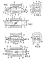
Figur 1 einen Teilvertikalschnitt durch eine Schaltbrücke mit betriebsfertig eingesetzter Kontaktbrücke und Kontaktfeder,Figur 2 einen Horizontalschnitt zuFigur 1, teils mit Draufsicht auf die Kontaktfeder und teils auf die Kontaktbrücke,Figur 3 eine Seitenansicht zuFigur 1,Figur 4 einen Teilvertikalschnitt durch eine Schaltbrückeentsprechend Figur 1, jedoch mit einer anders ausgestalteten Kontaktbrücke,Figur 5 einen Horizontalschnitt entsprechendFigur 2,Figur 6 eine Seitenansicht zuFigur 5,- Figur 7 eine anders ausgestaltete Schaltbrücke in der Schnittdarstellung gemäß Schnittlinie VII - VII in
Figur 8, Figur 8 einen Schnitt zu Figur 7 gemäß Schnittlinie VIII - VIII in Figur 7,Figur 9 wiederum eine anders ausgestaltete Schaltbrücke undFigur 10 einen Schnitt hierzu gemäß Schnittlinie X - X inFigur 9.
- FIG. 1 shows a partial vertical section through a switching bridge with the contact bridge and contact spring inserted ready for operation,
- FIG. 2 shows a horizontal section to FIG. 1, partly with a top view of the contact spring and partly onto the contact bridge,
- FIG. 3 shows a side view of FIG. 1,
- FIG. 4 shows a partial vertical section through a switching bridge corresponding to FIG. 1, but with a differently designed contact bridge,
- FIG. 5 shows a horizontal section corresponding to FIG. 2,
- FIG. 6 shows a side view of FIG. 5,
- FIG. 7 shows a differently configured switching bridge in the sectional view along section line VII - VII in FIG. 8,
- 8 shows a section to FIG. 7 along section line VIII-VIII in FIG. 7,
- Figure 9 in turn a differently designed switching bridge and
- FIG. 10 shows a section in accordance with section line X-X in FIG. 9.
Die Figuren 1 bis 3 zeigen einen Teilausschnitt aus einer Schaltbrücke 1 mit einem querverlaufenden Fenster 2. Die Schaltbrücke kann beliebig viele Fenster übereinander und/oder nebeneinander aufweisen, so daß sich je Fenster die nachfolgend erläuterte Konstruktion entsprechend oft wiederholt. Gemäß Fig. 1 sind zu beiden Seiten des Fensters Ausnehmungen 3 und 4 vorgesehen, so daß das eigentliche Fenster in dem Steg 5 vorgesehen ist. Die verbleibenden im Ränder der Schaltbrücke, die über den Steg 5 überstehen, können als Verstärkungsrippen ausgebildet sein. An der Oberseite des Steges 5 ist ein Vorsprung 6 angeformt, der zweckmäßigerweise rechteckig ausgebildet ist, wie Fig. 2 verdeutlicht. Dieser Vorsprung greift in eine Öffnung 7 einer Kontaktfeder 8 ein und hält diese in jeder Betriebsstellung, und zwar auch verdrehsicher. Wie Fig. 1 verdeutlicht, ist die Kontaktfeder 8 als konvex zu der zugehörigen darunter befindlichen Kontaktbrücke 11 gebogene Blattfeder ausgebildet. Die beiderseitigen Enden 9 und 10 der Kontakt- bzw. Blattfeder 8 und die Enden 12 und 13 der Kontaktbrücke 11 sind gemäß Fig. 1 etwas nach oben hin, d.h. konkav abgebogen. Dabei liegen die Enden unter Federdruck so aufeinander und wirken derart zusammen, daß die Kontaktbrücke 11 in Längsrichtung von der Kontaktfeder 8 gehalten ist. Wie Fig. 2 dazu verdeutlicht, ist die Kontaktbrücke 11 in Querrichtung von den Seitenwänden des Fensters 2 gehalten. Vorteilhafterweise weist die Kontaktbrücke 11 geradlinige Längskanten auf, besteht also im wesentlichen aus einem rechteckigen gut stromleitenden Metallstreifen. Bei dieser Anordnung und Halterung kommt die Kontaktbrücke praktisch nicht in reibende Berührung mit den Seitenwänden des Fensters 2 oder den weiteren Seitenflächen der Schaltbrücke 1, so daß sich kein Abrieb bilden kann.Figures 1 to 3 show a partial section of a
Bei dem Ausführungsbeispiel nach den Figuren 1 bis 3 ist die Kontaktbrücke 11 massiv ausgebildet und trägt auf der Unterseite Kontaktstücke 14 und 15.In the exemplary embodiment according to FIGS. 1 to 3, the
Wie aus Fig. 2 und 3 ersichtlich ist, ist die Kontaktfeder 8 mit zwei nach den Enden zu verlaufenden Längsschlitzen 18 versehen, die zweckmäßig innen in eine Abrundung 19 übergehen. Zu beiden Seiten des Schlitzes 18 entstehen so federnde Arme 16 und 17, wie aus Figur 2 für den linken Teil der Kontaktfeder 8 erkennbar ist.As can be seen from FIGS. 2 and 3, the
Das gleiche gilt auch für das rechte Ende der Kontakt- bzw. Blattfeder 8, welches in Fig. 2 abgebrochen und nicht gezeichnet ist. Durch diese Ausgestaltung der Kontaktfeder wird die Kontaktsicherheit noch weiterhin erhöht, weil die Kontaktfeder an vier Stellen auf die Kontaktbrücke 11 drückt.The same also applies to the right end of the contact or
Die Figuren 4 bis 6 veranschaulichen ein anderes Ausführungsbeispiel, auf welches auch die obigen Ausführungen sinngemäß zutreffen. Die mit dem Ausführungsbeispiel nach den Figuren 1 bis 3 übereinstimmenden Teile sind deshalb nicht noch einmal beschrieben und mit Bezugszeichen versehen. Die Kontaktbrücke 20 ist in diesem Falle etwas dünner, inaterial- und gewichtssparender ausgebildet. Hier ist auch die Kontaktbrücke 20 mit zwei nach den Enden zu verlaufenden Längsschlitzen 33 versehen, so daß zu beiden Seiten dieser Längsschlitze insgesamt vier, paarweise parallel zueinander verlaufende Arme 21, 22, 23 und 24 gebildet sind. Jeder dieser Arme trägt ein Kontaktstück 29, 30, 31 und 32. Dies ist eine Maßnahme, die zu einer weiteren Verbesserung der Kontaktsicherheit führt. Die konkav abgebogenen Enden der Kontaktfeder 34 arbeiten wieder mit den ebenfalls konkav abgebogenen Enden 25, 26, 27 und 28 der vorbeschriebenen Arme 21 bis 24 zusammen.Figures 4 to 6 illustrate one another exemplary embodiment, to which the above statements also apply mutatis mutandis. The parts corresponding to the exemplary embodiment according to FIGS. 1 to 3 are therefore not described again and provided with reference numerals. In this case, the
In den oben erläuterten Ausführungsbeispielen ist die Raststelle der als Blattfeder ausgebildeten Kontaktfeder eine Öffnung 7, in welche der Vorsprung 6 eingreift. Statt dessen kann man die Raststelle auch einfach als Querrippe, also z. B. senkrecht zur Bildebene der Fig. 1 verlaufend, ausbilden. Diese Querrippe kann nach unten gewölbt sein, so daß von oben ein in die Querrippe eingreifender Vorsprung eine formschlüssige Verbindung bzw. Halterung herstellt. Alternativ kann die Querrippe auch nach oben gewölbt sein. Diese kann dann in eine Kerbe der benachbarten Fensterwandung eingreifen bzw. in dieser anliegen.In the exemplary embodiments explained above, the latching point of the contact spring designed as a leaf spring is an opening 7 into which the
Die Figuren 7 und 8 zeigen ein weiteres bevorzugtes Ausführungsbeispiel einer erfindungsgemäßen Schaltbrücke. Hierbei besteht die Kontaktbrücke aus einem federnd elastischen bzw. selbstfedernden Material, und zwar aus einem elektrisch gut leitenden verhältnismäßig dünnen Metallstreifen. Die Kontaktbrücke ist in Form eines Rahmens 35 gebogen, wie vor allem Fig. 7 deutlich macht. Der Rahmen 35 besteht gemäß der Darstellung in Fig. 7 aus einem unteren nicht unterbrochenen Teil 36, auf dessen Unterseite die Kontaktstücke 48, 49 bzw. 50, 51 (Fig. 8) befestigt sind. Mit abgerundeten Ecken schließen sich an dieses Rahmenteil 36 nach oben führende Rahmenteile 37 und 38 an, die wiederum mit abgerundeten Ecken in die oberen nach innen weisenden Rahmenteile 39 und 40 übergehen. Der Rahmen 35 ist somit im wesentlichen rechteckig ausgebildet, wobei jedoch die Rahmenteile 39 und 40 in Ruhelage gemäß der ausgezogen gezeichneten Stellung nach Fig. 7 etwas schräg nach innen ansteigen. Die Kontaktstücke 48 bis 51 sind, wie angedeutet, auf der Außenseite des nicht unterbrochenen Teiles 36 des Rahmens angeordnet, und zwar nach den Enden dieses Teiles zu. Der Rahmen kann aus einem ununterbrochenen Metallstreifen bestehen, beispielsweise durch Abtrennen von einem Rohr und durch anschließendes Verformen hergestellt werden. Aus Fertigungsgründen ist es jedoch zweckmäßig, die Kontaktbrücke aus einem ebenflächigen Metallstreifen aus zustanzen und sodann zu einem im wesentlichen rechteckigen Rahmen zu verformen. In diesem Falle ist es zweckmäßig die Enden 41 und 42 des Metallstreifens im mittleren Bereich des Fensters 2 der Schaltbrücke 1 umzubiegen und die Formgebung so vorzunehmen, daß diese Enden dicht aneinander liegen. Vorteilhafterweise sind die Enden 41 und 42 an den aneinander liegenden Flächen mit einer Silberschicht versehen, so daß ein guter Stromübergang gewährleistet ist. Dadurch daß die Kontaktbrücke als Rahmen 35 ausgebildet ist eine zweifache stromleitende Verbindung zwischen den Kontaktstücken 48 und 49 einerseits und den Kontaktstücken 50 und 51 andererseits vorhanden. Das selbstfedernde bzw. federnd elastische Material ist so gewählt, daß der Rahmen 35 gleichzeitig die Kontaktdruckfedern bildet.FIGS. 7 and 8 show a further preferred exemplary embodiment of a switching bridge according to the invention. Here, the contact bridge consists of a resiliently elastic or self-resilient material, namely an electrically thin, relatively thin metal strip. The contact bridge is bent in the form of a
Bei dem dargestellten Ausführungsbeispiel sind die Enden 41 und 42 der Rahmenteile 39 und 40 nach innen, d.h. in Fig. 7 nach unten im wesentlichen um 90° umgebogen. Im Bereich dieser Enden und einem anschließenden Teil der Rahmenteile 39, 40 ist je eine Aussparung 43, z. B. in Rechteckform vorgesehen. In diese beiden Aussparungen greift ein Vorsprung 6 ein, welcher wie dargestellt in das Fenster 2 hineinragt. Bei der automatischen Bestückung der Schaltbrücke 1 mit den rahmenförmigen Kontaktbrücken ist es nur erforderlich, den Rahmen 35 von einer Seite in das Fenster 2 einzuschieben. Wenn dies beispielsweise von der linken Seite nach Fig. 7 erfolgt, so wird durch den Vorsprung 6 das Rahmenteil 39 zunächst federnd nach unten gedrückt bis die richtige Stellung erreicht ist und der Vorsprung 6 in die Aussparungen 43 eingreift und die Stellung des Rahmens sichert. Zu besseren Halterung können noch an den Innenkanten der Aussparungen 43 nach unten umgebogene Teile 44 und 45 vorgesehen sein.In the illustrated embodiment, the ends 41 and 42 of the
Alternativ ist es auch möglich, die vorgeschriebenen Enden der Rahmenteile 39 und 40 nach außen umzubiegen und statt des Vorsprunges 6 eine Aussparung in diesem Teil der Fensterwand vorzusehen, so daß die umgebogenen Enden in diese Aussparung eingreifen und wieder dicht aufeinander liegen.Alternatively, it is also possible to bend the prescribed ends of the
Um die Kontaktsicherheit zu erhöhen, ist der Rahmen 35, wie in Figur 8 ersichtlich, in den Bereichen beiderseitig des Fensters 2 mit Schlitzen 46 und 47 versehen, und es sind demgemäß die beschriebenen vier Kontaktstücke 48 bis 51 angebracht.In order to increase the contact security, the
Figur 7 zeigt ferner, daß zu beiden Seiten des Fensters 2 leicht schräg nach außen ansteigende Anlageflächen 52 und 53 an der Schaltbrücke 1 angeformt sind. In Betriebsstellung, die strichpunktiert mit den Bezugszeichen 54 versehen ist, können sich die Rahmenteile 39 und 40 an diesen Anlageflächen 52 und 53 abstützen. Die Rahmenteile 39 und 40 führen zwischen der Ruhestellung und der Betriebsstellung eine gewisse Schwenkbewegung aus, wie ein Vergleich der ausgezogen gezeichneten Lage mit der Betriebsstellung zeigt. Dabei führen die umgebogenen Enden 41 und 42 eine gewisse Wälzbewegung zueinander aus, so daß an den beschriebenen aneinanderliegenden Flächen ein Selbstreinigungseffekt auftritt und stets ein guter Stromübergang gewährleistet ist.Figure 7 also shows that on both sides of the
Bei dem Ausführungsbeispiel nach den Figuren 9 und 10 ist die Kontaktfeder 67 C-förmig gebogen. Die nach innen weisenden Enden 68 und 69 der Kontaktfeder 67 stützen sich an je einem gefalteten Teil 77 und 79 bzw. 78 der Kontaktbrücke 75 ab. Die Kontaktbrücke 75 trägt wieder auf der Unterseite Kontaktstücke 71, 72, 73 und 74. Zur Erhöhung der Kontaktsicherheit weisen sowohl die Kontaktfeder 67 als auch die Kontaktbrücke 75 längsverlaufende Schlitze 70 und 76 auf (Figur 10).In the exemplary embodiment according to FIGS. 9 and 10, the
Es sei noch bemerkt, daß besonders die oben erläuterten Ausführungsbeispiele nach den Figuren 7 bis 10 der Deutlichkeit halber sehr stark vergrößert gezeichnet sind, und zwar in einem Maßstab von etwa 10 : 1.It should also be noted that, in particular, the exemplary embodiments explained above in accordance with FIGS. 7 to 10 have been drawn in a greatly enlarged manner for the sake of clarity, specifically on a scale of approximately 10: 1.
Claims (14)
Priority Applications (3)
| Application Number | Priority Date | Filing Date | Title |
|---|---|---|---|
| AT84112789T ATE46983T1 (en) | 1984-03-31 | 1984-10-24 | SWITCHING JUMPER FOR ELECTRICAL SWITCHING DEVICES, ESPECIALLY FOR CONTACTORS. |
| ES541266A ES8608222A1 (en) | 1984-03-31 | 1985-03-14 | Switching bridge for electrical switching devices, especially for contactors |
| CA000477586A CA1266074A (en) | 1984-03-31 | 1985-03-27 | Switch bridge arrangement for an electrical switch |
Applications Claiming Priority (2)
| Application Number | Priority Date | Filing Date | Title |
|---|---|---|---|
| EP84103593 | 1984-03-31 | ||
| EP84103593 | 1984-03-31 |
Related Child Applications (1)
| Application Number | Title | Priority Date | Filing Date |
|---|---|---|---|
| EP88104209.7 Division-Into | 1988-03-17 |
Publications (3)
| Publication Number | Publication Date |
|---|---|
| EP0162952A1 EP0162952A1 (en) | 1985-12-04 |
| EP0162952B1 true EP0162952B1 (en) | 1989-10-04 |
| EP0162952B2 EP0162952B2 (en) | 1992-12-23 |
Family
ID=8191854
Family Applications (2)
| Application Number | Title | Priority Date | Filing Date |
|---|---|---|---|
| EP88104209A Expired - Lifetime EP0304539B1 (en) | 1984-03-31 | 1984-10-24 | Switching bridge for electrical switching devices, particularly for contactors |
| EP84112789A Expired - Lifetime EP0162952B2 (en) | 1984-03-31 | 1984-10-24 | Switching bridge for electrical switching devices, particularly for contactors |
Family Applications Before (1)
| Application Number | Title | Priority Date | Filing Date |
|---|---|---|---|
| EP88104209A Expired - Lifetime EP0304539B1 (en) | 1984-03-31 | 1984-10-24 | Switching bridge for electrical switching devices, particularly for contactors |
Country Status (3)
| Country | Link |
|---|---|
| US (1) | US4594484A (en) |
| EP (2) | EP0304539B1 (en) |
| DE (2) | DE3486065D1 (en) |
Cited By (1)
| Publication number | Priority date | Publication date | Assignee | Title |
|---|---|---|---|---|
| DE4439295C1 (en) * | 1994-11-07 | 1996-06-05 | Inovan Stroebe | Contact holder for contact bridge in electric switch |
Families Citing this family (22)
| Publication number | Priority date | Publication date | Assignee | Title |
|---|---|---|---|---|
| US4924040A (en) * | 1986-09-25 | 1990-05-08 | Illinois Tool Works Inc. | Electrical switching apparatus |
| DE4117120A1 (en) * | 1991-05-25 | 1992-11-26 | Abb Patent Gmbh | Contact arrangement for electrical pushbutton switch - incorporates contact holder imparting turning force to spring leaf contact wiping switch contacts together |
| US5265904A (en) * | 1993-01-07 | 1993-11-30 | Ford Motor Company | Airbag cover with integral horn switch |
| US5265905A (en) * | 1993-01-07 | 1993-11-30 | Ford Motor Company | Air bag cover horn blow switch assembly |
| DE4323878A1 (en) * | 1993-07-16 | 1995-01-19 | Abb Patent Gmbh | Push button module for switching |
| US6084488A (en) * | 1998-04-03 | 2000-07-04 | Pass & Seymour, Inc. | Compact high current relay |
| US7400477B2 (en) * | 1998-08-24 | 2008-07-15 | Leviton Manufacturing Co., Inc. | Method of distribution of a circuit interrupting device with reset lockout and reverse wiring protection |
| US6180899B1 (en) * | 1999-01-04 | 2001-01-30 | Siemens Energy & Automation, Inc. | Semi-bifurcated electrical contacts |
| SE516457C2 (en) * | 1999-01-28 | 2002-01-15 | Asea Brown Boveri | Switch in contactor |
| US6958671B2 (en) * | 2001-11-15 | 2005-10-25 | Square D Company | Electrical contactor with positive temperature coefficient resistivity element |
| EP1577919B1 (en) * | 2004-03-15 | 2014-09-10 | Omron Corporation | Electromagnetic relay |
| CN1321430C (en) * | 2006-03-06 | 2007-06-13 | 通领科技集团有限公司 | Earthing fault breaker actuator having pressure balance auto compensation |
| CN103474300B (en) | 2008-07-07 | 2016-03-09 | 立维腾制造有限公司 | A kind of fault circuit interrupter device |
| DE102010043352A1 (en) * | 2010-11-03 | 2012-05-03 | Tyco Electronics Amp Gmbh | Contact arrangement for a relay with two load current paths and relays with contact arrangement |
| DE102010063172A1 (en) * | 2010-12-15 | 2012-06-21 | Tyco Electronics Amp Gmbh | Contact arrangement for a relay with two load current paths and a cross-current path and relay with contact arrangement |
| DE102011008834A1 (en) * | 2011-01-19 | 2012-07-19 | Abb Ag | Service switching device |
| DE102015212817A1 (en) * | 2015-07-08 | 2017-01-12 | Te Connectivity Germany Gmbh | Contact bridge arrangement for an electrical switching element |
| DE102015212818A1 (en) | 2015-07-08 | 2017-01-12 | Te Connectivity Germany Gmbh | Contact bridge arrangement for an electrical switching element |
| CN107331581A (en) * | 2017-08-25 | 2017-11-07 | 戴丁志 | Damping positions formula contactor |
| WO2022188984A1 (en) * | 2021-03-11 | 2022-09-15 | Pierburg Gmbh | Contact bridge device for a switch of a high-voltage contactor or high-voltage relay |
| DE112021007255A5 (en) * | 2021-03-11 | 2023-12-28 | Pierburg Gmbh | CONTACT BRIDGE DEVICE FOR A SWITCH OF A HIGH VOLTAGE CONTACTOR OR HIGH VOLTAGE RELAY |
| CN115621055A (en) | 2021-07-15 | 2023-01-17 | 霍尼韦尔国际公司 | Switching element comprising an integrated movable carrier assembly |
Family Cites Families (7)
| Publication number | Priority date | Publication date | Assignee | Title |
|---|---|---|---|---|
| CH235649A (en) * | 1942-12-28 | 1944-12-15 | Sauter Ag | Cam switches. |
| US3260824A (en) * | 1963-07-29 | 1966-07-12 | Arrow Hart & Hegeman Electric | Low energy non-arcing electric relay construction |
| DE1894372U (en) * | 1964-03-26 | 1964-06-11 | Stotz Kontakt Gmbh | SWITCHING DEVICE, IN PARTICULAR AIR PROTECTION FOR HIGH INRUSH CURRENT PEAKS. |
| FR1435781A (en) * | 1964-06-22 | 1966-04-22 | Telemecanique Electrique | Improvements to the contact poles of current breaking devices |
| JPS4844312B1 (en) * | 1968-08-05 | 1973-12-24 | ||
| FR2257141B1 (en) * | 1974-01-03 | 1978-03-10 | Telemecanique Electrique | |
| DE8126801U1 (en) * | 1981-09-14 | 1982-03-04 | Siemens AG, 1000 Berlin und 8000 München | "Contact arrangement for electrical switching devices |
-
1984
- 1984-10-24 DE DE8888104209T patent/DE3486065D1/en not_active Expired - Fee Related
- 1984-10-24 EP EP88104209A patent/EP0304539B1/en not_active Expired - Lifetime
- 1984-10-24 EP EP84112789A patent/EP0162952B2/en not_active Expired - Lifetime
- 1984-10-24 DE DE8484112789T patent/DE3480038D1/en not_active Expired
-
1985
- 1985-03-18 US US06/713,267 patent/US4594484A/en not_active Expired - Fee Related
Cited By (1)
| Publication number | Priority date | Publication date | Assignee | Title |
|---|---|---|---|---|
| DE4439295C1 (en) * | 1994-11-07 | 1996-06-05 | Inovan Stroebe | Contact holder for contact bridge in electric switch |
Also Published As
| Publication number | Publication date |
|---|---|
| DE3486065D1 (en) | 1993-03-18 |
| DE3480038D1 (en) | 1989-11-09 |
| EP0162952B2 (en) | 1992-12-23 |
| EP0162952A1 (en) | 1985-12-04 |
| EP0304539A1 (en) | 1989-03-01 |
| US4594484A (en) | 1986-06-10 |
| EP0304539B1 (en) | 1993-02-03 |
Similar Documents
| Publication | Publication Date | Title |
|---|---|---|
| EP0162952B1 (en) | Switching bridge for electrical switching devices, particularly for contactors | |
| EP0375088B1 (en) | Disconnecting arrangement for the main current path of a power circuit breaker | |
| EP0554519B1 (en) | Grounding terminal | |
| WO2017081001A1 (en) | Connection clamp | |
| DE2356024A1 (en) | KEYBOARD | |
| DE102006031584B4 (en) | Miniaturized electrical switch | |
| DE8320066U1 (en) | Slide switch | |
| DE19714163C2 (en) | Pushbutton switch | |
| DE580085C (en) | Push button switch | |
| DE3247319A1 (en) | ELECTRIC PUSH BUTTON SWITCH WITH A SWIVEL BEARING PRESSURE BAR | |
| DE8521611U1 (en) | Push-button operated overcurrent protection switch | |
| DE2248029A1 (en) | CARRIER FOR THE MOVING CONTACTS OF A SWITCHING DEVICE | |
| DE1273589B (en) | Selector button set for telecommunication systems with spring-loaded button units that perform a stroke movement | |
| DE2914677A1 (en) | SLIDING SWITCH | |
| DE2547278C2 (en) | Electrical snap switch | |
| EP0017820A1 (en) | Extension device for push-button actuated mechanisms | |
| DE2913019C2 (en) | Push button switch | |
| DE19707835A1 (en) | Electrical switching device | |
| DE7504400U (en) | Electric switch | |
| DE3018810A1 (en) | PUSH BUTTON SWITCH | |
| DE7903379U1 (en) | Push button switch | |
| DE3624254A1 (en) | SNAP SWITCH | |
| DE1115804B (en) | Electrical terminal block for plugging onto a C-shaped mounting rail | |
| DE2350041A1 (en) | Snap-action switch for office machines - has contact arm and snap spring made in one piece from wire in form of yoke etc. | |
| DE3120894C2 (en) | Electric switch |
Legal Events
| Date | Code | Title | Description |
|---|---|---|---|
| PUAI | Public reference made under article 153(3) epc to a published international application that has entered the european phase |
Free format text: ORIGINAL CODE: 0009012 |
|
| AK | Designated contracting states |
Designated state(s): AT BE CH DE FR GB IT LI LU NL SE |
|
| 17P | Request for examination filed |
Effective date: 19860521 |
|
| 17Q | First examination report despatched |
Effective date: 19871126 |
|
| GRAA | (expected) grant |
Free format text: ORIGINAL CODE: 0009210 |
|
| AK | Designated contracting states |
Kind code of ref document: B1 Designated state(s): AT BE CH DE FR GB IT LI LU NL SE |
|
| PG25 | Lapsed in a contracting state [announced via postgrant information from national office to epo] |
Ref country code: SE Effective date: 19891004 Ref country code: NL Effective date: 19891004 Ref country code: BE Effective date: 19891004 |
|
| REF | Corresponds to: |
Ref document number: 46983 Country of ref document: AT Date of ref document: 19891015 Kind code of ref document: T |
|
| XX | Miscellaneous (additional remarks) |
Free format text: TEILANMELDUNG 88104209 EINGEREICHT AM 17.03.88. |
|
| PG25 | Lapsed in a contracting state [announced via postgrant information from national office to epo] |
Ref country code: LU Free format text: LAPSE BECAUSE OF NON-PAYMENT OF DUE FEES Effective date: 19891031 |
|
| REF | Corresponds to: |
Ref document number: 3480038 Country of ref document: DE Date of ref document: 19891109 |
|
| ITF | It: translation for a ep patent filed | ||
| ET | Fr: translation filed | ||
| GBT | Gb: translation of ep patent filed (gb section 77(6)(a)/1977) | ||
| NLV1 | Nl: lapsed or annulled due to failure to fulfill the requirements of art. 29p and 29m of the patents act | ||
| PLBI | Opposition filed |
Free format text: ORIGINAL CODE: 0009260 |
|
| 26 | Opposition filed |
Opponent name: SIEMENS AKTIENGESELLSCHAFT, BERLIN UND MUENCHEN Effective date: 19900628 |
|
| RAP2 | Party data changed (patent owner data changed or rights of a patent transferred) |
Owner name: SQUARE D COMPANY (DEUTSCHLAND) GMBH |
|
| ITTA | It: last paid annual fee | ||
| PGFP | Annual fee paid to national office [announced via postgrant information from national office to epo] |
Ref country code: CH Payment date: 19921023 Year of fee payment: 9 |
|
| PGFP | Annual fee paid to national office [announced via postgrant information from national office to epo] |
Ref country code: AT Payment date: 19921028 Year of fee payment: 9 |
|
| PUAH | Patent maintained in amended form |
Free format text: ORIGINAL CODE: 0009272 |
|
| STAA | Information on the status of an ep patent application or granted ep patent |
Free format text: STATUS: PATENT MAINTAINED AS AMENDED |
|
| 27A | Patent maintained in amended form |
Effective date: 19921223 |
|
| AK | Designated contracting states |
Kind code of ref document: B2 Designated state(s): AT BE CH DE FR GB IT LI LU NL SE |
|
| REG | Reference to a national code |
Ref country code: CH Ref legal event code: AEN |
|
| GBTA | Gb: translation of amended ep patent filed (gb section 77(6)(b)/1977) |
Effective date: 19930203 |
|
| ET3 | Fr: translation filed ** decision concerning opposition | ||
| ITF | It: translation for a ep patent filed | ||
| PG25 | Lapsed in a contracting state [announced via postgrant information from national office to epo] |
Ref country code: AT Effective date: 19931024 |
|
| PG25 | Lapsed in a contracting state [announced via postgrant information from national office to epo] |
Ref country code: LI Effective date: 19931031 Ref country code: CH Effective date: 19931031 |
|
| REG | Reference to a national code |
Ref country code: CH Ref legal event code: PL |
|
| PGFP | Annual fee paid to national office [announced via postgrant information from national office to epo] |
Ref country code: GB Payment date: 19951018 Year of fee payment: 12 |
|
| PGFP | Annual fee paid to national office [announced via postgrant information from national office to epo] |
Ref country code: FR Payment date: 19951031 Year of fee payment: 12 |
|
| PGFP | Annual fee paid to national office [announced via postgrant information from national office to epo] |
Ref country code: DE Payment date: 19951221 Year of fee payment: 12 |
|
| PG25 | Lapsed in a contracting state [announced via postgrant information from national office to epo] |
Ref country code: GB Effective date: 19961024 |
|
| GBPC | Gb: european patent ceased through non-payment of renewal fee |
Effective date: 19961024 |
|
| PG25 | Lapsed in a contracting state [announced via postgrant information from national office to epo] |
Ref country code: FR Effective date: 19970630 |
|
| PG25 | Lapsed in a contracting state [announced via postgrant information from national office to epo] |
Ref country code: DE Effective date: 19970701 |
|
| REG | Reference to a national code |
Ref country code: FR Ref legal event code: ST |