EP0162949B1 - Method and apparatus for measuring slag-forming conditions within converter - Google Patents
Method and apparatus for measuring slag-forming conditions within converter Download PDFInfo
- Publication number
- EP0162949B1 EP0162949B1 EP84110571A EP84110571A EP0162949B1 EP 0162949 B1 EP0162949 B1 EP 0162949B1 EP 84110571 A EP84110571 A EP 84110571A EP 84110571 A EP84110571 A EP 84110571A EP 0162949 B1 EP0162949 B1 EP 0162949B1
- Authority
- EP
- European Patent Office
- Prior art keywords
- slag
- converter
- vessel
- light
- blowing
- Prior art date
- Legal status (The legal status is an assumption and is not a legal conclusion. Google has not performed a legal analysis and makes no representation as to the accuracy of the status listed.)
- Expired
Links
Images


Classifications
-
- C—CHEMISTRY; METALLURGY
- C21—METALLURGY OF IRON
- C21C—PROCESSING OF PIG-IRON, e.g. REFINING, MANUFACTURE OF WROUGHT-IRON OR STEEL; TREATMENT IN MOLTEN STATE OF FERROUS ALLOYS
- C21C5/00—Manufacture of carbon-steel, e.g. plain mild steel, medium carbon steel or cast steel or stainless steel
- C21C5/28—Manufacture of steel in the converter
- C21C5/42—Constructional features of converters
- C21C5/46—Details or accessories
- C21C5/4673—Measuring and sampling devices
-
- C—CHEMISTRY; METALLURGY
- C21—METALLURGY OF IRON
- C21C—PROCESSING OF PIG-IRON, e.g. REFINING, MANUFACTURE OF WROUGHT-IRON OR STEEL; TREATMENT IN MOLTEN STATE OF FERROUS ALLOYS
- C21C5/00—Manufacture of carbon-steel, e.g. plain mild steel, medium carbon steel or cast steel or stainless steel
- C21C5/28—Manufacture of steel in the converter
- C21C5/30—Regulating or controlling the blowing
Definitions
- the present invention relates to a method and apparatus for directly observing slag-forming conditions within a converter used for steel refining.
- Slag foaming occurs due to several slag conditions, such as the slag composition, viscosity, the total amount of oxygen in the slag, etc. Too extensive slag foaming causes the slag and even molten steel to overflow the converter mouth, which overflow is referred to as "slopping". Of course, the composition of the molten steel and the steel yield are greatly influenced by slopping. Also, various problems are caused, such as reduction in the operational efficiency and in the calorific content of the recovered gases, impairment of the operational environment, e.g., generation of brown smoke, and damage to the steelmaking devices. Slopping therefore must be suppressed as much as possible.
- Japanese Unexamined Patent Publication (Kokai) No. 52-101618 discloses a method for estimating the amount of slag by calculating the oxygen balance based on information on the waste gases during blowing and then estimating the amount of oxides formed in the converter, i.e., the molten slag. In this method, however, there is an unavoidable time delay due to the gas analysis and mathematical analysis. In addition, since slopping is not dependent upon just the amount of molten slag alone, the accuracy of prediction of slopping is not very high.
- acoustic measuring method changes in the frequency and magnitude of the acoustics generated in the converter are monitored to estimate the slag level and to predict slopping.
- a microwave is directly projected into the converter interior to directly measure the slag level based on the FM radar technique and to predict slopping.
- the energy emission from the upper and lower parts of the converter body is detected as temperature, and the occurrence and magnitude of slopping are predicted based on the temperature magnitude and peak values.
- the acoustic measuring method, vibration measuring method, method for measuring the inner pressure of a converter, and method for measuring the surface temperature of the converter body are all indirect measuring methods and suffer from low accuracies of prediction of slopping due to the inability to quantitatively measure the slag level or conditions.
- the method using a microwave gauge enables direct measurement of the slag level, but suffer from the fact that it is not easy to detect or estimate abnormalities by microwave measurement, since the melt, slag, gases, and the like effect considerably complicated movement in the converter during blowing. In addition, this method requires sophisticated signal processing, which increases the cost of the measuring device.
- the present inventors recognized, as a result of various studies concerning abnormal reactions in a converter, that the occurrence of such abnormal reactions is closely related to the slag-forming conditions, i.e., the foaming behavior of slag.
- the present inventors studied the foaming behavior of slag and discovered that the light intensity of the gaseous atmosphere and the wavelength characteristics of light emitted from the gaseous atmosphere considerably differ from those of the slag. The present inventors discovered that they could positively utilize such differences to detect the foaming behavior.
- the present invention provides a method and apparatus for directly observing slag-forming conditions, i.e., the slag-foaming conditions, in a converter during blowing, thereby allowing more precise and speedy observation than in the prior art and contributing to a highly accurate converter operation.
- the method according to the present invention is characterized in that at least one light-detecting device observing the vessel-interior light is disposed in at least one throughhole of the side wall of a converter so as to face the vessel interior and observe the slag-forming conditions.
- the apparatus comprises a light-detecting device including a receptor, which receptor is disposed in a throughhole of the side wall of a converter so as to face the vessel interior, and a device for detecting the intensity and/or wavelength of a light signal input from the light-detecting device.
- Fig. 1 is a cross-sectional view of a top-blowing converter, schematically showing an embodiment of mounting a light-detecting device observing the vessel-interior light in the converter;
- Figure 1 is a cross-sectional view of a top-blowing converter, schematically showing an embodiment of mounting a device for observing the vessel-interior light.
- a converter 1 is provided, on its side wall 2, with at least one throughhole 4 opening into the vessel interior 3.
- At least one light-detecting device 5 observing the vessel-interior light is disposed in the throughhole 4 to face the vessel interior 3 and observes the intensity or the wavelength of the light emitted from the slag and gaseous atmosphere within the converter 1.
- This light-detecting device 5 may be a photometer and is hereinafter referred to as the photometer 5.
- Fig. 1 only one throughhole and observation device are shown.
- Figures 2A to 2C show non-immersion portions 8 of the converter side wall 2, i.e., in the converter upright position, tilting position for tapping, and tilting position for charging the pig iron from the ladle, respectively.
- the portion of the converter wall 2 where a trunnion shaft 6 is rigidly secured and the region around that portion are not immersed within a melt 7.
- This portion and region, shown by the hatching are the non-immersion portion 8.
- the throughholes 4 can be formed through the non-immersion portion 8 to prevent the melt 7 from entering the throughholes 4.
- the photometers 5 can also be removably inserted into the tapping hole. When the molten steel is tapped through the tapping holes, the photometers 5 are removed therefrom.
- FIGs 3A through 3C, Fig. 4, and Fig. 5 illustrate the principle of the present invention, Figs. 3A through 3C showing the portions of mounting the devices for observing vessel-interior light and Figs. 4 and 5 showing time charts on the level of detected light signals.
- three photometers 5a, 5b, and 5c are arranged as seen in the vertical direction of the converter, so as to measure the vessel-interior light at the levels Xa, Xb, and Xc, respectively.
- the position of the throughholes 4, i.e., their distance from the bottom or mouth of the converter 1, must be empirically determined by the size and capacity of the converter 1. In the case of a single throughhole 4, the throughhole 4 must be located at the highest target slag level. In the case of plurality of throughholes 4, the highest and lowest throughholes 4 must be located straddling the highest target slag level.
- Figure 4 shows the light signal (ordinate) detected by any one of the photometers 5a, 5b, and 5c and then subjected to signal processing with the aid of an appropriate filter.
- the abscissa of Fig. 4 indicates the blowing time periods, the former period when the gaseous atmosphere is present beneath the level Xa, Xb, or Xc and the latter being when foaming slag is present beneath the levels Xa, Xb, or Xc.
- Figure 5 illustrates the results of continuous measurement of the vessel-interior light by the photometers 5a through 5c. Under the slag-foaming conditions shown in Fig. 3A, all of the photometers 5a through 5c face or are exposed to the gaseous atmosphere, which indicates that the slag-foaming level y is located beneath the level Xc.
- the photometers 5a and 5b face or are exposed to the gaseous atmosphere and the photometer 5c faces or is exposed to the foaming slag.
- the slag-foaming level y is therefore located beneath the level of the converter mouth 9 and between the levels Xb and Xc.
- the slag-foaming level y is therefore located between the level of the converter mouth 9 and the level Xa of the photometer 5a.
- the complicated foaming behavior of slag can therefore be accurately monitored by means of mounting a plurality of the photometers in the vertical direction and continuously measuring the vessel-interior light during the operation of the converter 1. If necessary, photometers may also be mounted along the width of the converter 1.
- the intensity of light of the gaseous atmosphere and the wavelength characteristics of light emitted from the gaseous atmosphere considerably differ from those of the slag. Therefore, by direct observation of the vessel-interior light, it is possible to distinguish, without signal processing of the light, the light upon facing or exposure to the slag from the light upon facing or exposure to the gaseous atmosphere. However, if the vessel-interior light is subjected to signal processing with regard to the intensity or wavelength of the light, a clearer image of the slag-forming conditions can be obtained. Also as is described in detail hereinbelow, the obtained signals can be advantageously utilized for controlling various blowing operations.
- slag-foaming behavior Using the slag-foaming behavior, one can preliminarily determine slag-forming criteria specifying the relationship between such behavior and slag-forming conditions. Therefore, according to an embodiment of the present invention, it is possible to compare the detected intensity and/or wavelength of the vessel-interior light with the slag-forming criteria determined for specific slag-forming conditions, such as formation of dephosphorizing and/or non-slopping slag.
- the slag-forming criteria are determined for each converter having a specified structure and vessel volume and for each blowing condition. the value detected by the photometers 5a through 5c (Figs. 3A through 3C) is compared with the slag-forming criteria, thereby achieving detection of slag-forming conditions.
- slag-forming criteria is as follows.
- the slag-forming level y arrives at the level Xa of the higest photmeter 5a, this means there is excessive slag formation and a high possibility of slopping.
- the level Xa can therefore be established as the slag-forming criterion indicating excessive formation of slag.
- the slag-forming criteria are determined for each type of slag formation. That is, dephosphorization requires formation of a dephosphorizing slag having an appropriate total amount of iron-oxide for a normal dephosphorization reaction and also having a sufficient volume.
- the formation of the dephosphorizing slag can be verified by monitoring the slag-forming level y, e.g., at the lowest level Xc of the photometer 5c. If the level of slag is beneath the lowest level Xc during the dephosphorizing period, abnormality in slag formation occurs.
- FIGS. 6 and 7 are partial cross-sectional views of a converter, showing different mounting structures of a photometer.
- a photometer 5 is mounted in the throughhole 4 via a protective tube 11 having an inner cylinder 110.
- a cooling-water circulating channel 111 is formed in the protective tube 11. Cooling water w is supplied into the cooling-water circulating channel 111 via one of conduits 112. The water w is withdrawn via the other conduit 112.
- the photometer 5 is installed within the inner cylinder 110 in such a manner that its active side faces the vessel interior.
- Purge gas such as N 2 , Ar, C0 2 , or another inert gas g, is supplied to and passed through the inner cylinder 110 and then ejected through the aperture 113 into the vessel. During its passage and ejection, the purge gas cools the photometer 5 and prevents gases including dust, slag, or the like from entering the inner cylinder 110.
- the signal detected by the photometer 5 is input via a cable 12 into a signal processing device 13, such as a transmission filter, a computing device 14, and a display device 15.
- a signal processing device 13 such as a transmission filter, a computing device 14, and a display device 15.
- the converter operation may be controlled either automatically or by a human operator.
- automatic control the signal detected by the photometer 5 is compared with the slag-forming criteria preliminarily input into the computing device 14 so as to automatically detect the slag-forming conditions.
- a warning signal or operating command is thereupon generated from the computing device 14 to various controlling devices (not shown).
- control by a human operator the operator watches detected values indicated on the display device 15 and compares them with predetermined slag-forming criteria, to control the converter operation.
- Figure 7 shows another examples of the photometer in Fig. 7, the same reference numerals and symbols as those of Fig. 6 indicate identical members.
- An optical conductor 51 i.e., a body capable of transmitting at a low loss the light emitted from a high temperature body, e.g., a quartz-based optical fiber, is located in the inner cylinder 110 of the protective tube 11.
- the optical conductor 51 is connected to the body 52 of the photometer 5, which is disposed at an appropriate position outside the converter.
- the structure shown in Fig. 7 is particularly advantageous, since the body 52 of photometer 5, which is expensive, can be located a safe distance from the high-temperature wall 2.
- the photometer 5 is not limited to any particular form provided that it can measure the intensity and/or wavelength of the vessel-interior light.
- the photometer 5 includes various assemblies a MOS or CCD device assembled with an optical filter, and a lens; a spectrometer and a photomultiplier; and an optical thermometer and a detector of the temperature profile.
- Figures 8, 9, and 10 show still another structure for mounting a photometer on a displacement mechanism disposed in the neighborhood of the converter and provided with means for retractably inserting the photometer into the throughhole.
- a support stand 21 located at the neighborhood of the converter 1 is equipped with a photometer 22.
- the photometer 22 includes an optical conductor and a receptor 23 at the front end thereof.
- the receptor 23 can be retractably advanced into the throughhole 4 by means of the displacement mechanism 24 which is secured to the supporting stand 21.
- the receptor 23 can therefore be timely inserted into the throughhole 4 when the vessel interior is to be observed and can be kept protected from such detrimental environments as thermal load and dusts during the operation period, e.g., the tapping period, in which the vessel interior is not to be observed.
- the tapping hole can therefore be utilized as the throughhole 4.
- the vessel-interior light received by the receptor 23 is transmitted via connector 25 into a photoelectric converter 26 for generating an electrical signal.
- the electric signal is input into an image processor 27 for detecting the intensity and/or wavelength of the vessel-interior light.
- the detected signal is shown on a display 28 of the vessel-interior conditions or a display 29 of the slag level.
- an inner brickwork lining 2a and steel mantle 2b have an aperture of, e.g., 500 mm diameter.
- a cylindrical body 4a has an inner refractory lining for defining the throughhole 4 and is welded to the steel mantle 2b.
- a flange 4c having an aperture is secured to the cylindrical body 4a.
- a seal cap 4d is attached to the flange 4c by bolts and has a conical-shaped seal surface spread toward the vessel exterior.
- a probe 22a provided with a photoconductor therein is equipped with a conical seal body 22b, the conical shape of which body allowing gas-tight contact with the seal cap 4d.
- the position of the receptor 23 being provided at the probe tip end is adjustable by an adjusting bar 22c and adjusting nut 22d, so that the probe tip end 23 can be positioned at an appropriate position to receive the vessel-interior light.
- Th ' e probe 22a is displaced toward and locked to the seal cap 4d by displacement mechanism 24 (Fig. 8).
- the spring 22e which is guided along the spring guide 22f, is not indispensable but is preferable to further displace or and thus compress the probe 22a against the seal cap 4d.
- a supporting platform 30 having wheels 30a and 30b is displaced along a pair of rails 21 a.
- the wheels 30a are attached to the supporting platform 30 so that they are engaged to the upper and lower surfaces of the rails 21 a, while the wheels 30b are attached to the supporting platform 30 so that they are engaged to the inner surfaces of the rails 21a.
- the probe 22a is provided, at its rear end as seen from the throughhole (not shown), metallic fittings 22g and is loosely connected to the displacing platform 30c via the metallic fittings 22g and a bolt 30e.
- the displacing platform 30c is provided with a probe-supporting base 30d on which the probe 22a is freely placed.
- the displacing platform 30 can be an automotive one directly equipped with a driving mechanism or one which is driven via a rod, gear, wire, or the like by means of an electric motor, pneumatic means, or hydraulic means installed separate from the displacing platform 30.
- the driven mechanism shown in Figs. 10A through 10C are hydraulic.
- the hydraulic cylinder 24a is connected via the rod 24b to the metallic fittings 22h, thereby transmitting the force of the hydraulic cylinder 24a to the probe 22a.
- the metallic fitting 22h the rod 24b are loosely connected with one another. Since the probe 22a is loosely connected to both the displacing platform 30 and the rod 24b as is described above and, further, since a clearance can be formed between the wheels 30b and one of the rails 21 a, the probe 22a is somewhat displaceable in any direction, thereby making it possible to realize a further highly gas-tight contact between the conical seal body 22b and the conical seal surface of the seal cap 4d.
- the probe 22a including the photo-conductor therein, is generally a dual tube. Therefore, the annular space between the inner and outer tubes can be used as the passage for an inert gas blown toward the end of the probe so as to cool it or clean the receptor located at its end.
- the photoelectrically conducted signal of the vessel-interior light is divided into a plurality of ranges of wavelength.
- the proportion of area of the light to the total image area of the receptor is computed with regard to each wavelength range, and the computed area proportion compared with predetermined slag-forming criteria.
- melt 7 is charged in the converter 1.
- a photometer 22 is displaced until it is inserted into the through-hole.
- Oxygen begins to be blown through a lance 16, and then refining is initiated.
- the flux materials are charged into the converter 1 and form molten slag.
- the amount of slag 31 is still relatively small in Fig. 1 (I), and the circular field of the receptor 23 gives a white image of the high-temperature gaseous atmosphere 32 of converter, as shown in Fig. 11 (I').
- the surface of the slag 31 (Fig. 11 (11)) is vigorously stirred by the oxygen blown through the lance 16 and by the CO gas or the like formed due to the blowing reactions.
- the vessel-interior light can be subjected to wavelength separation by means of, for example, a blue-transmitting filter, so as to pass through the filter light having the wavelength range where the intensity of light emitted from the slag is dominant.
- the filtered light is subjected to a computing process so as to obtain the proportion of the filtered light to the entire area of the circular field of the receptor. The obtained surface-area proportion is plotted, as shown in Fig. 13, with time.
- A indicates the pseudo slag signal generated during the blowing start period, in which the temperature of the gaseous atmosphere is low, and B indicates an abrupt increase of the surface-area ratio and thus occurrence of slopping.
- B indicates an abrupt increase of the surface-area ratio and thus occurrence of slopping.
- the surface-area ratio Prior to the occurrence of slopping, the surface-area ratio intensely varies. The slopping can therefore be predicted on the basis of such intense change.
- a throughhole formed at the nonimmersing portion 8 (Figs. 2A, 2B, and 2C) cools due to non-contact with the molten steel and further cools if the inert purge gas is blown to it through the probe tip end.
- deposits on the throughhole can be melted due to the latent heat of the slag when the end of the throughhole is exposed to the foaming slag. In this case, the deposits can be blown out by inert purge gas, thus preventing accumulation of deposits.
- Oxygen-containing purge gas is preferred purge gas discovered after various investigations of the assignee of the present application.
- the coolant gas of the probe can be blown at an almost constant rate to attain the intended cooling
- the flow rate of the oxygen-containing purge gas for attaining the intended purge greatly varies depending upon the position of the throughhole, quality and quantity of the vessel's content, temperature, and vessel interior conditions. Control of the flow-rate for the purge is therefore difficult. It is more desirable and convenient to control and to vary the oxygen content of the purge gas.
- inert gas is fed from a source A and is separately blown into conduit systems 34 and 40.
- the conduit system 34 includes a stop valve 35 and a reducing valve 36, a flow-rate adjusting device 37 with an orifice and flow-control valve, and a stop valve 38 successively arranged in the flow direction.
- the inert gas blown through the conduit system 34 flows via a flexible hose 39 into an inner cylinder 62 (Fig. 15) which is connected via an inlet port 63 (Fig. 15) to the flexible hose 39.
- the inert gas is further blown through a small aperture 42 of a front tip 41 screwed into a probe 61.
- the inner gas is then released from a tip aperture 43 into the vessel interior while preventing fogging or contamination of a front glass 67 of the probe 61.
- the inert gas flowing through the conduit system 40 is mixed with oxygen fed from a source B into the conduit system 44.
- the mixture gas flows via a flexible hose 45 and inlet port 65 into an outer cylinder 64 to cool the outer surface of the inner cylinder 62 and the front tip 41.
- the mixture gas is released into the vessel interior from the outer cylinder 64 through an opening 66.
- the flow rate ratio of oxygen to inert gas is adjusted by a flow-rate controller 33 connected to the conduit systems 40 and 44.
- the reverse Z 0 symbol indicates the check valves located upstream of the joining point of the conduit systems 40 and 44.
- the probe 61 includes a photo conductor therein.
- the symbol 26, 27, 28, and 29 indicate a photoelectric converter, image processor, display device of the vessel-interior condition, and slap level-display device, respectively.
- the amount of slag is controlled on the basis of the detected slag-forming conditions so as to maintain the amount of slag within an appropriate range at a high accuracy.
- This embodiment aims not only to predict the occurrence of slopping but also to enhance operational efficiency and improve the steel quality by means of observing the slag level at a high accuracy, monitoring the variation tendencies in the slag level, and suppressing detrimental tendencies. A typical example of this embodiment is described with reference to Fig. 16.
- the level of slag at which slopping is likely to occur is denoted by 72.
- Reference numeral 74 indicates the change of the slag level with time, allowing one to maintain the level of slag lower than the level 72 over the entire blowing period.
- the level of slag at with the slag formation is poor is denoted by 73.
- Reference numeral 75 indicates the change of the slag level with time, allowing one to ensure, at a certain initial preparatory blowing period, a slag level higher than 75.
- target slag-level control is effected to control the level of slag between the levels 74 and 75 during the entire blowing period.
- the symbols I, II, and III indicate the slag-level control actions.
- information is extracted from the signal obtained by the photometer so as to monitor the surface-area proportion of yellow base color to the entire color signal and variation in that proportion.
- the proportion and variation are compared with predetermined color criteria.
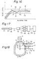
- Figure 17 is a block diagram for computing and outputting the proportion described above.
- the probe 61 more specifically the photo-conductor, is provided with a connector 25 and photoelectric converter 26.
- the light detected by the probe 61 is electrically converted to an image signal 77 which is transmitted to the wavelength-range divider 78.
- Analog signals 79 i.e., one (B-blue) having a wavelength range of from approximately 0.3 to 0.4 ⁇ m, another (G-green) having a wavelength range of from approximately 0.4 to 0.6 pm, and the other (R-red) havingh a wavelength range of from approximately 0.6 to 0.8 pm, are generated by the wavelength range-divider 78.
- the analog signals are converted at an appropriate threshold level to binary signals 80 which are input into an area-computing device 81.
- the binary R signal, the binary G signal, and the bindary B signal are multiplied by a count pulse of, for example, 0.134 useç (7 MHz) in a reset cycle of 16.7 msec, and the number of pulses of R-G on and B off is counted.
- the area proportion of yellow base color is counted for each 16.7 msec cycle and is generated as the output signal of yellow 82, which is observed with a area-proportion display device 91.
- control operations controlling the oxygen-blowing rate; controlling the lance height; charging the auxiliary raw materials, such as lime or iron ore; and controlling the bottom-flowing gas rate are carried out. This allows stabilization of the slag composition to drastically reduce the occurrence of slopping and to improve the slag quality.
- one or more of dolomite powder, quick lime powder, coal powder, and cokes powder is blown, into the vessel preferably through an additional throughhole of the side wall, upon the prediction of occurrence of slopping so as to stabilize the blowing.
- Figure 18 shows a 170 ton top- and bottom-blowing converter which has a top lance 16 for blowing 0 2 and a bottom nozzle 17 for blowing C0 2 .
- Throughholes 4 were formed at levels 1.5 m, 2.5 m, and 3.5 m beneath the converter mouth 9.
- Protective tubes 11 having an inner cylinder 110 (Fig 7) were inserted into the throughholes 4.
- An optical conductor 51 having a diameter of 12 mm, was stationarily located in each cylinder 110 and was connected to each body of photometers 52.
- the photometers 52 were ITV cameras equipped with short wavelength- transmitting filters. Signals from the ITV cameras were transmitted into signal processing units 13 including digital memories to store the signals in the digital memories. The digital information was subjected to signal processing for generating an image. The difference in the intensity of light between the gaseous atmosphere and the foaming slag was more distinct than by conventional photometers.
- the temperature of the foaming level of slag was intermittently measured by lowering the sublance equipped with a consumable thermometer at the tip end thereof.
- the present invention attains measurement of the slag level y at a high accuracy.
- the present invention attains, furthermore, continuous measurement, which makes it possible to successfully detect or predict the dynamic slag-forming behavior within the convertor.
- Table 1 shows the relationship between the total number of heats in which the foaming level of slag y arrived at the respective levels of the photometers and the occurrence of slopping, the relationship being determined by investigations of the assignee.
- the slag-forming criterion was defined as the time when the photometer 5a detected the foaming slag, i.e., the slag-forming criterion indicated abnormal or excessive formation of slag.
- the intensity of vessel-interior light was continuously measured during blowing by the photometers 5a, 5b, and 5c.
- the warning signal shown by Z in Fig. 19 was generated to warn of abnormal or excessive formation of slag.
- control actions such as reduction in the 0 2 -flow rate, through the top-blowing lance 16, and charging of unburnt dolomite into the converter 1, were carried out. Due to such control actions, the occurrence of slopping could be reduced to as low as 0.5% or less.
- a converter having an outer diameter of approximately 7 m and a height from the bottom to mouth of 8 m was pierced by a throughhole 150 mm in diameter through the side wall.
- a probe having an outer diameter of 80 mm and a photoconductor having an outer diameter of 40 mm were used.
- the purge gas blowing exerted no detrimental influence upon the blowing operation and quality of tapped steels.
- a 170 ton top- and bottom-blowing converter 8 m in height was charged with melt 1.5 m in depth.
- a throughhole was formed at the converter wall 2.5 m perpendicularly under the mouth.
- An optical fiber 12 mm in diameter was used as as photoconductor and inserted into a cooling protective tube.
- a CCD color-camera was used as a photoelectric converter.
- the slag level was detected by method as described with reference to Fig. 17 of computing the area ratio of yellow base color. The relationship between the area ratio of yellow base color and the position of the optical fiber was so established that the area ratio was 50% when the slag level coincided at the center of field of the optical fiber.
- the area ratio 100% and 0% corresponded to the slag levels above and below the throughhole, respectively.
- the threshold levels in the binary circuit were K 35%, G 35%, and B 25%.
- the area ratio signal of yellow base color 82 from a circuit 81 was divided and transmitted into two circuits. In one of the circuits, the area ratio signal was converted in the binary circuit 83 having appropriate threshold level (10%), into a binary signal 84. In the other circuit, the area-ratio signal of yellow base color 82 was passed through a high-pass filter 85 (cut frequency of 5Hz) and then converted to a positive value at a circuit 86. The positive signal was converted to a binary signal 88 in the binary circuit 87 having an appropriate threshold level (50%), which binary signal 88 indicated the changes in the area ratio. The two binary signals 84 and 88 were input into a decision circuit 89 which produces a final control signal 90. The possibility of occurrence of slopping was decided as shown in Table 3.
- Figs. 21 through 23 One or more of the operating objects were manipulated as described with reference to Figs. 21 through 23.
- Fig. 21 when the slag level varies during operation as shown by a curve 71 and exceeds the target slag level 76 at the points 92 and 93 and when there is no possibility of occurrence of slopping, an increase in the bottom-blowing flow rate (No. 1) is effective to atain the target slag level 76.
- a decrease in the bottom-blowing flow rate (No. 1) is first employed. If the slag level seemingly will not reach the target level 76 approximately 2 minutes after the decrease in bottom-blowing flow rate, the lance is lifted (No. 2) or the oxygen-flow rate is decreased (No. 3) to promote the foaming of slag.
- Blowing was carried out as in Example 3 except for the following:
- another throughhole was formed in a non-immersing portion of the side wall of the converter to charge the auxiliary raw materials therethrough.
- the additional throughhole was equipped with a nozzle for blowing auxiliary raw materials, purge gas and carrier gas.
- Purge gas consisting of 75% CO 2 and 25% 0 2 was blown without interruption at a rate of 120 Nm 3 /hr to prevent clogging of the additional aperture.
- the CO 2 gas was blown with flow rate by 500 Nm 3 /hr as carrier gas, and coke powder (5 mm or less) ws blown into the vessel interior.
- lump dolomite was charged.
- the coke-powder injection is more effective than the lump dolomite charging.
- Example 4 Blowing was carried out as in Example 4 except for the following: Instead of addition of another throughhole for injection of pulverized auxiliary raw materials using purge gas to the throughhole for observation of the vessel interior, and assembled probe was equipped, which had an observation device and injection mechanism.
- This kind of probe is a modified one shown in Fig. 15 in the following points.
- Inlet port 65 into an outer cylinder 64 is connected to the powder injection unit.
- the injected powder in carrier gas is released into the vessel interior from the outer cylinder 64.
- the probe 61 includes a photoconductor therein.
- the purge gas is released from an inlet port 63 and blown through a small aperture 42 of a front tip 41 screwed into a probe 61.
- the purge gas is mixed with oxygen concentration with 30 to 40% by volume.
Description
- The present invention relates to a method and apparatus for directly observing slag-forming conditions within a converter used for steel refining.
- In refining molten pig iron and steel in a converter, pure oxygen is ejected from a lance inserted through the mouth of the converter into the converter body (below "vessel"). The oxygen is blown onto the molten steel to both effect decarburization and stir the molten steel. In addition, flux is charged into the converter to form molten slag, thereby effecting dephosphorization, desulfurization, or the like due to the reactions between the molten slag and steel.
- Slag foaming occurs due to several slag conditions, such as the slag composition, viscosity, the total amount of oxygen in the slag, etc. Too extensive slag foaming causes the slag and even molten steel to overflow the converter mouth, which overflow is referred to as "slopping". Of course, the composition of the molten steel and the steel yield are greatly influenced by slopping. Also, various problems are caused, such as reduction in the operational efficiency and in the calorific content of the recovered gases, impairment of the operational environment, e.g., generation of brown smoke, and damage to the steelmaking devices. Slopping therefore must be suppressed as much as possible.
- Various proposals have been made on how to enable prompt prediction of the slag conditions within a converter and hence realize optional converter operation without slopping.
- Japanese Unexamined Patent Publication (Kokai) No. 52-101618 discloses a method for estimating the amount of slag by calculating the oxygen balance based on information on the waste gases during blowing and then estimating the amount of oxides formed in the converter, i.e., the molten slag. In this method, however, there is an unavoidable time delay due to the gas analysis and mathematical analysis. In addition, since slopping is not dependent upon just the amount of molten slag alone, the accuracy of prediction of slopping is not very high.
- Various attempts have also been made on detecting the slag level by physical means. These include an acoustic measuring method (Japanese Unexamined Patent Publication No. 54-33790), a vibration measuring method (Japanese Unexamined Patent Publication No. 54-114,414), a method for measuring the inner pressure of a converter (Japanese Unexamined Patent Publication No. 55-104,417), a method using a microwave gauge (Japanese Unexamined Patent Publication No. 57-140812), and a method for measuring the surface temperature of the converter body (Japanese Unexamined Patent Publication No. 58-48615).
- In the acoustic measuring method, changes in the frequency and magnitude of the acoustics generated in the converter are monitored to estimate the slag level and to predict slopping.
- In the vibration measuring method, changes in the magnitude of lance vibration and the wave transition of the lance vibration are monitored during blowing to estimate the slag level or conditions and then to predict slopping.
- In the method for measuring the inner pressure of a converter, variations in the ejecting pressure of the waste gases through the converter mouth are monitored to predict slopping.
- In the method using a microwave gauge, a microwave is directly projected into the converter interior to directly measure the slag level based on the FM radar technique and to predict slopping.
- In the method for measuring the surface temperature of a converter body, the energy emission from the upper and lower parts of the converter body is detected as temperature, and the occurrence and magnitude of slopping are predicted based on the temperature magnitude and peak values.
- The acoustic measuring method, vibration measuring method, method for measuring the inner pressure of a converter, and method for measuring the surface temperature of the converter body are all indirect measuring methods and suffer from low accuracies of prediction of slopping due to the inability to quantitatively measure the slag level or conditions. The method using a microwave gauge enables direct measurement of the slag level, but suffer from the fact that it is not easy to detect or estimate abnormalities by microwave measurement, since the melt, slag, gases, and the like effect considerably complicated movement in the converter during blowing. In addition, this method requires sophisticated signal processing, which increases the cost of the measuring device.
- The present inventors recognized, as a result of various studies concerning abnormal reactions in a converter, that the occurrence of such abnormal reactions is closely related to the slag-forming conditions, i.e., the foaming behavior of slag. The present inventors studied the foaming behavior of slag and discovered that the light intensity of the gaseous atmosphere and the wavelength characteristics of light emitted from the gaseous atmosphere considerably differ from those of the slag. The present inventors discovered that they could positively utilize such differences to detect the foaming behavior.
- The present invention provides a method and apparatus for directly observing slag-forming conditions, i.e., the slag-foaming conditions, in a converter during blowing, thereby allowing more precise and speedy observation than in the prior art and contributing to a highly accurate converter operation.
- The method according to the present invention is characterized in that at least one light-detecting device observing the vessel-interior light is disposed in at least one throughhole of the side wall of a converter so as to face the vessel interior and observe the slag-forming conditions.
- The apparatus according to the present invention comprises a light-detecting device including a receptor, which receptor is disposed in a throughhole of the side wall of a converter so as to face the vessel interior, and a device for detecting the intensity and/or wavelength of a light signal input from the light-detecting device.
- Dependent claims comprise additional features of the invention.
- In the drawings, Fig. 1 is a cross-sectional view of a top-blowing converter, schematically showing an embodiment of mounting a light-detecting device observing the vessel-interior light in the converter;
- Figs. 2A through 2C are cross-sectional views of a converter, showing non-immersion portions of the converter side wall;
- Figs. 3A through 3C, Fig. 4, and Fig. 5 illustrate the principle of the present invention, Figs. 3A through 3C showing the position of mounting the devices for observing vessel-interior light and Figs. 4 and 5 showing time charts on the level of detected light signals;
- Figs. 6 and 7 are partial cross-sectional views of a converter, showing different mounting structures of a device for observing the vessel-interior light;
- Fig. 8 is a schematic drawing of the arrangement of the device for observing the vessel-interior light, relative to the converter;
- Fig. 9 is a partial cross-sectional view of a converter and a cross-sectional view of the device for observing the vessel-interior light, which device is gas-tightly inserted into a throughhole of the converter;
- Fig. 10A is an overall view of a supporting platform with a displacement mechanism;
- Figs. 10B through 10E are partial views of the supporting platform shown in Fig. 10A;
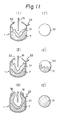
- Figs. 11 (I), (I'), (II), (11'), (III), and (III') illustrate the blowing conditions of a converter and the operation of the device for observing vessel-interior light according to the present invention;
- Fig. 12 graphically illustrates the relationship between the wavelength and intensity of light emitted from the slag and gaseous atmosphere above the slag;
- Fig. 13 illustrates an example of a vessel-interior display, showing the variation in the surface-area proportion with the lapse of blowing time;
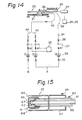
- Fig. 14 illustrates an example of the piping of purge gas;
- Fig. 15 is a partial cross-sectional view of an example of a probe according to the present invention;
- Fig. 16 illustrates the relationship between the slag level and blowing time;
- Fig. 17 is a block diagram of another example of the device for observing the vessel-interior light;
- Fig. 18 shows the mounting position of devices for observing the vessel-interior light mounted on a top- and bottom-blowing converter;
- Fig. 19 is a time chart of light signals detected by the devices shown in Fig. 18 and of the slag level detected by using a sublance;
- Fig. 20 is a block diagram of method of detecting the slag-forming conditions according to the present invention; and
- Figs. 21 through 23 illustrate the slag level during blowing and a method for controlling it.
- Figure 1 is a cross-sectional view of a top-blowing converter, schematically showing an embodiment of mounting a device for observing the vessel-interior light. Referring to Fig. 1, a
converter 1 is provided, on itsside wall 2, with at least onethroughhole 4 opening into thevessel interior 3. At least one light-detectingdevice 5 observing the vessel-interior light is disposed in thethroughhole 4 to face thevessel interior 3 and observes the intensity or the wavelength of the light emitted from the slag and gaseous atmosphere within theconverter 1. This light-detectingdevice 5 may be a photometer and is hereinafter referred to as thephotometer 5. In Fig. 1, only one throughhole and observation device are shown. - It is possible, based on the measurement of intensity and or wavelength of the light, to monitor whether slag-foaming occurs above or beneath a processing level X of the
photometer 5. - Figures 2A to 2C show
non-immersion portions 8 of theconverter side wall 2, i.e., in the converter upright position, tilting position for tapping, and tilting position for charging the pig iron from the ladle, respectively. In each of the positions shown in Figs. 2A, 2B, and 2C, the portion of theconverter wall 2 where atrunnion shaft 6 is rigidly secured and the region around that portion are not immersed within amelt 7. This portion and region, shown by the hatching are thenon-immersion portion 8. Thethroughholes 4 can be formed through thenon-immersion portion 8 to prevent themelt 7 from entering thethroughholes 4. - As is described below, the
photometers 5 can also be removably inserted into the tapping hole. When the molten steel is tapped through the tapping holes, thephotometers 5 are removed therefrom. - Figures 3A through 3C, Fig. 4, and Fig. 5 illustrate the principle of the present invention, Figs. 3A through 3C showing the portions of mounting the devices for observing vessel-interior light and Figs. 4 and 5 showing time charts on the level of detected light signals. Referring to Figs. 3A through 3C, three
photometers throughholes 4, i.e., their distance from the bottom or mouth of theconverter 1, must be empirically determined by the size and capacity of theconverter 1. In the case of asingle throughhole 4, thethroughhole 4 must be located at the highest target slag level. In the case of plurality ofthroughholes 4, the highest andlowest throughholes 4 must be located straddling the highest target slag level. - Figure 4 shows the light signal (ordinate) detected by any one of the
photometers - Figure 5 illustrates the results of continuous measurement of the vessel-interior light by the
photometers 5a through 5c. Under the slag-foaming conditions shown in Fig. 3A, all of thephotometers 5a through 5c face or are exposed to the gaseous atmosphere, which indicates that the slag-foaming level y is located beneath the level Xc. - Under the slag-foaming conditions shown in Fig. 3B, the
photometers photometer 5c faces or is exposed to the foaming slag. The slag-foaming level y is therefore located beneath the level of theconverter mouth 9 and between the levels Xb and Xc. - Under the slag-foaming conditions shown in Fig. 3C, all of the
photometers 5a through 5c face or are exposed to the slag. The slag-foaming level y is therefore located between the level of theconverter mouth 9 and the level Xa of thephotometer 5a. - The complicated foaming behavior of slag can therefore be accurately monitored by means of mounting a plurality of the photometers in the vertical direction and continuously measuring the vessel-interior light during the operation of the
converter 1. If necessary, photometers may also be mounted along the width of theconverter 1. - As described above, the intensity of light of the gaseous atmosphere and the wavelength characteristics of light emitted from the gaseous atmosphere considerably differ from those of the slag. Therefore, by direct observation of the vessel-interior light, it is possible to distinguish, without signal processing of the light, the light upon facing or exposure to the slag from the light upon facing or exposure to the gaseous atmosphere. However, if the vessel-interior light is subjected to signal processing with regard to the intensity or wavelength of the light, a clearer image of the slag-forming conditions can be obtained. Also as is described in detail hereinbelow, the obtained signals can be advantageously utilized for controlling various blowing operations.
- Using the slag-foaming behavior, one can preliminarily determine slag-forming criteria specifying the relationship between such behavior and slag-forming conditions. Therefore, according to an embodiment of the present invention, it is possible to compare the detected intensity and/or wavelength of the vessel-interior light with the slag-forming criteria determined for specific slag-forming conditions, such as formation of dephosphorizing and/or non-slopping slag. The slag-forming criteria are determined for each converter having a specified structure and vessel volume and for each blowing condition. the value detected by the
photometers 5a through 5c (Figs. 3A through 3C) is compared with the slag-forming criteria, thereby achieving detection of slag-forming conditions. - An example of the slag-forming criteria is as follows. When the slag-forming level y arrives at the level Xa of the
higest photmeter 5a, this means there is excessive slag formation and a high possibility of slopping. The level Xa can therefore be established as the slag-forming criterion indicating excessive formation of slag. - The slag-forming criteria are determined for each type of slag formation. That is, dephosphorization requires formation of a dephosphorizing slag having an appropriate total amount of iron-oxide for a normal dephosphorization reaction and also having a sufficient volume. The formation of the dephosphorizing slag can be verified by monitoring the slag-forming level y, e.g., at the lowest level Xc of the
photometer 5c. If the level of slag is beneath the lowest level Xc during the dephosphorizing period, abnormality in slag formation occurs. - Although the above explanation was made with reference to a plurality of
photometers 5a through 5c arranged in theconverter 1, it is possible to satisfactorily observe the slag-forming conditions even by a single photometer, as shown in Fig. 1 and as described hereinbelow. - Figures 6 and 7 are partial cross-sectional views of a converter, showing different mounting structures of a photometer. Referring to Fig. 6, a
photometer 5 is mounted in thethroughhole 4 via aprotective tube 11 having aninner cylinder 110. A cooling-water circulating channel 111 is formed in theprotective tube 11. Cooling water w is supplied into the cooling-water circulating channel 111 via one ofconduits 112. The water w is withdrawn via theother conduit 112. Thephotometer 5 is installed within theinner cylinder 110 in such a manner that its active side faces the vessel interior. Purge gas, such as N2, Ar, C02, or another inert gas g, is supplied to and passed through theinner cylinder 110 and then ejected through theaperture 113 into the vessel. During its passage and ejection, the purge gas cools thephotometer 5 and prevents gases including dust, slag, or the like from entering theinner cylinder 110. - The signal detected by the
photometer 5 is input via acable 12 into asignal processing device 13, such as a transmission filter, acomputing device 14, and adisplay device 15. - The converter operation may be controlled either automatically or by a human operator. In automatic control, the signal detected by the
photometer 5 is compared with the slag-forming criteria preliminarily input into thecomputing device 14 so as to automatically detect the slag-forming conditions. A warning signal or operating command is thereupon generated from thecomputing device 14 to various controlling devices (not shown). In control by a human operator, the operator watches detected values indicated on thedisplay device 15 and compares them with predetermined slag-forming criteria, to control the converter operation. - Figure 7 shows another examples of the photometer in Fig. 7, the same reference numerals and symbols as those of Fig. 6 indicate identical members. An
optical conductor 51, i.e., a body capable of transmitting at a low loss the light emitted from a high temperature body, e.g., a quartz-based optical fiber, is located in theinner cylinder 110 of theprotective tube 11. Theoptical conductor 51 is connected to thebody 52 of thephotometer 5, which is disposed at an appropriate position outside the converter. The structure shown in Fig. 7 is particularly advantageous, since thebody 52 ofphotometer 5, which is expensive, can be located a safe distance from the high-temperature wall 2. - The
photometer 5 is not limited to any particular form provided that it can measure the intensity and/or wavelength of the vessel-interior light. Thephotometer 5 includes various assemblies a MOS or CCD device assembled with an optical filter, and a lens; a spectrometer and a photomultiplier; and an optical thermometer and a detector of the temperature profile. - Figures 8, 9, and 10 show still another structure for mounting a photometer on a displacement mechanism disposed in the neighborhood of the converter and provided with means for retractably inserting the photometer into the throughhole.
- Referring to Fig. 8, a
support stand 21 located at the neighborhood of theconverter 1 is equipped with aphotometer 22. Thephotometer 22 includes an optical conductor and areceptor 23 at the front end thereof. Thereceptor 23 can be retractably advanced into thethroughhole 4 by means of thedisplacement mechanism 24 which is secured to the supportingstand 21. Thereceptor 23 can therefore be timely inserted into thethroughhole 4 when the vessel interior is to be observed and can be kept protected from such detrimental environments as thermal load and dusts during the operation period, e.g., the tapping period, in which the vessel interior is not to be observed. The tapping hole can therefore be utilized as thethroughhole 4. The vessel-interior light received by thereceptor 23 is transmitted viaconnector 25 into aphotoelectric converter 26 for generating an electrical signal. The electric signal is input into animage processor 27 for detecting the intensity and/or wavelength of the vessel-interior light. The detected signal is shown on adisplay 28 of the vessel-interior conditions or adisplay 29 of the slag level. - Referring to Fig. 9, showing a detailed structure of the photometer as well as an example of the seal mechanism of the
throughhole 4, aninner brickwork lining 2a andsteel mantle 2b have an aperture of, e.g., 500 mm diameter. Acylindrical body 4a has an inner refractory lining for defining thethroughhole 4 and is welded to thesteel mantle 2b. Aflange 4c having an aperture is secured to thecylindrical body 4a. Aseal cap 4d is attached to theflange 4c by bolts and has a conical-shaped seal surface spread toward the vessel exterior. Aprobe 22a provided with a photoconductor therein (not shown) is equipped with aconical seal body 22b, the conical shape of which body allowing gas-tight contact with theseal cap 4d. The position of thereceptor 23 being provided at the probe tip end is adjustable by an adjusting bar 22c and adjustingnut 22d, so that theprobe tip end 23 can be positioned at an appropriate position to receive the vessel-interior light. Th'e probe 22a is displaced toward and locked to theseal cap 4d by displacement mechanism 24 (Fig. 8). Thespring 22e, which is guided along thespring guide 22f, is not indispensable but is preferable to further displace or and thus compress theprobe 22a against theseal cap 4d. - Refering to Figs. 10A, 10B, and 10C, showing an example of the
displacement mechanism 24, a supportingplatform 30 havingwheels rails 21 a. Thewheels 30a are attached to the supportingplatform 30 so that they are engaged to the upper and lower surfaces of therails 21 a, while thewheels 30b are attached to the supportingplatform 30 so that they are engaged to the inner surfaces of therails 21a. Theprobe 22a is provided, at its rear end as seen from the throughhole (not shown),metallic fittings 22g and is loosely connected to thedisplacing platform 30c via themetallic fittings 22g and a bolt 30e. The displacingplatform 30c is provided with a probe-supportingbase 30d on which theprobe 22a is freely placed. - The
displacement mechanism 24 described above with reference to Figs. 10A, 10B, and 10C, retractably displaces the receptor included in theprobe tip end 23 into thethroughhole 4 by means of carrying the displacingplatform 30 along therails 21a. The displacingplatform 30 can be an automotive one directly equipped with a driving mechanism or one which is driven via a rod, gear, wire, or the like by means of an electric motor, pneumatic means, or hydraulic means installed separate from the displacingplatform 30. - The driven mechanism shown in Figs. 10A through 10C are hydraulic. The
hydraulic cylinder 24a is connected via therod 24b to themetallic fittings 22h, thereby transmitting the force of thehydraulic cylinder 24a to theprobe 22a. As shown in Figs. 10D and 10E, themetallic fitting 22h therod 24b are loosely connected with one another. Since theprobe 22a is loosely connected to both the displacingplatform 30 and therod 24b as is described above and, further, since a clearance can be formed between thewheels 30b and one of therails 21 a, theprobe 22a is somewhat displaceable in any direction, thereby making it possible to realize a further highly gas-tight contact between theconical seal body 22b and the conical seal surface of theseal cap 4d. - The
probe 22a, including the photo-conductor therein, is generally a dual tube. Therefore, the annular space between the inner and outer tubes can be used as the passage for an inert gas blown toward the end of the probe so as to cool it or clean the receptor located at its end. - In an embodiment of the method according to the present invention, described with reference to Figs. 11,12, and 13, the photoelectrically conducted signal of the vessel-interior light is divided into a plurality of ranges of wavelength. The proportion of area of the light to the total image area of the receptor is computed with regard to each wavelength range, and the computed area proportion compared with predetermined slag-forming criteria.
- Referring to Figs. 11 (I, I') through (III, III') the
melt 7 is charged in theconverter 1. Aphotometer 22 is displaced until it is inserted into the through-hole. Oxygen begins to be blown through alance 16, and then refining is initiated. The flux materials are charged into theconverter 1 and form molten slag. - The amount of
slag 31 is still relatively small in Fig. 1 (I), and the circular field of thereceptor 23 gives a white image of the high-temperaturegaseous atmosphere 32 of converter, as shown in Fig. 11 (I'). When the slag formation further advances, the surface of the slag 31 (Fig. 11 (11)) is vigorously stirred by the oxygen blown through thelance 16 and by the CO gas or the like formed due to the blowing reactions. Theslag 31, which is in an emulsion state and which has a lower temperature than the high-temperaturegaseous atmosphere 32, is detected by the circular field of thereceptor 22 as yellow waves. When the slag 31 (Fig. 11 (111)) overflows the convertor mouth and slopping occurs, the circular field of thereceptor 23 is entirely yellow. The above changes in the conditions of slag formation can be continuously observed by television with the naked eye or can be recorded as is explained with reference to Figs. 12 and 13. - The intensity-wavelenth relationship of slag becomes clearly different from that of the gaseous atmosphere above the slag, as shown in Fig. 12, when the slap forming proceeds to an appreciable extent and the temperature of the gaseous atmosphere is higher than that of the slag. Therefore, the vessel-interior light can be subjected to wavelength separation by means of, for example, a blue-transmitting filter, so as to pass through the filter light having the wavelength range where the intensity of light emitted from the slag is dominant. The filtered light is subjected to a computing process so as to obtain the proportion of the filtered light to the entire area of the circular field of the receptor. The obtained surface-area proportion is plotted, as shown in Fig. 13, with time.
- Referring to Fig. 13, A indicates the pseudo slag signal generated during the blowing start period, in which the temperature of the gaseous atmosphere is low, and B indicates an abrupt increase of the surface-area ratio and thus occurrence of slopping. Prior to the occurrence of slopping, the surface-area ratio intensely varies. The slopping can therefore be predicted on the basis of such intense change.
- When a throughhole is exposed to the gaseous atmosphere, the vessel's contents progressively deposit on the throughhole, resulting in clogging. In an embodiment of the method of the present invention, described in with reference to Figs. 14 and 15, observation of the vessel interior is carried out while blowing through the probe an oxygen-containing purge gas to prevent clogging of the throughhole. Clogging of throughhole is one of the most serious problems impeding the observation of the vessel interior. The situation is not so serious when using the tapping hole as the throughhole for observation. Since the tapping hole is brought into contact with molten steel at each tapping, the tapping hole can be maintained at an extremely high temperature even during the blowing period. The deposits on the tapping hole, composed of contents of the vessel, therefore cannot solidify that much and can be blown out even by inert purge gas blown through the probe tip end. Contrary to this, a throughhole formed at the nonimmersing portion 8 (Figs. 2A, 2B, and 2C) cools due to non-contact with the molten steel and further cools if the inert purge gas is blown to it through the probe tip end. Still, deposits on the throughhole can be melted due to the latent heat of the slag when the end of the throughhole is exposed to the foaming slag. In this case, the deposits can be blown out by inert purge gas, thus preventing accumulation of deposits.
- Oxygen-containing purge gas is preferred purge gas discovered after various investigations of the assignee of the present application. In this regard, while the coolant gas of the probe can be blown at an almost constant rate to attain the intended cooling, the flow rate of the oxygen-containing purge gas for attaining the intended purge greatly varies depending upon the position of the throughhole, quality and quantity of the vessel's content, temperature, and vessel interior conditions. Control of the flow-rate for the purge is therefore difficult. It is more desirable and convenient to control and to vary the oxygen content of the purge gas.
- Referring to Fig. 14, inert gas is fed from a source A and is separately blown into
conduit systems 34 and 40. The conduit system 34 includes astop valve 35 and a reducingvalve 36, a flow-rate adjusting device 37 with an orifice and flow-control valve, and astop valve 38 successively arranged in the flow direction. The inert gas blown through the conduit system 34 flows via aflexible hose 39 into an inner cylinder 62 (Fig. 15) which is connected via an inlet port 63 (Fig. 15) to theflexible hose 39. The inert gas is further blown through asmall aperture 42 of afront tip 41 screwed into aprobe 61. The inner gas is then released from atip aperture 43 into the vessel interior while preventing fogging or contamination of afront glass 67 of theprobe 61. - The inert gas flowing through the
conduit system 40 is mixed with oxygen fed from a source B into theconduit system 44. The mixture gas flows via aflexible hose 45 andinlet port 65 into anouter cylinder 64 to cool the outer surface of theinner cylinder 62 and thefront tip 41. The mixture gas is released into the vessel interior from theouter cylinder 64 through anopening 66. The flow rate ratio of oxygen to inert gas is adjusted by a flow-rate controller 33 connected to theconduit systems reverse Z 0 symbol indicates the check valves located upstream of the joining point of theconduit systems probe 61 includes a photo conductor therein. Thesymbol - In an embodiment of the method according to the present invention, the amount of slag is controlled on the basis of the detected slag-forming conditions so as to maintain the amount of slag within an appropriate range at a high accuracy. This embodiment aims not only to predict the occurrence of slopping but also to enhance operational efficiency and improve the steel quality by means of observing the slag level at a high accuracy, monitoring the variation tendencies in the slag level, and suppressing detrimental tendencies. A typical example of this embodiment is described with reference to Fig. 16.
- Referring to Fig. 16, the level of slag at which slopping is likely to occur is denoted by 72.
Reference numeral 74 indicates the change of the slag level with time, allowing one to maintain the level of slag lower than thelevel 72 over the entire blowing period. The level of slag at with the slag formation is poor is denoted by 73.Reference numeral 75 indicates the change of the slag level with time, allowing one to ensure, at a certain initial preparatory blowing period, a slag level higher than 75. In this example, target slag-level control is effected to control the level of slag between thelevels - In an embodiment of the present invention, information is extracted from the signal obtained by the photometer so as to monitor the surface-area proportion of yellow base color to the entire color signal and variation in that proportion. The proportion and variation are compared with predetermined color criteria. This embodiment enables very accurate detection of the slag-forming conditions, as described with reference to Fig. 17.
- Figure 17 is a block diagram for computing and outputting the proportion described above. The
probe 61, more specifically the photo-conductor, is provided with aconnector 25 andphotoelectric converter 26. The light detected by theprobe 61 is electrically converted to animage signal 77 which is transmitted to the wavelength-range divider 78. Analog signals 79, i.e., one (B-blue) having a wavelength range of from approximately 0.3 to 0.4 µm, another (G-green) having a wavelength range of from approximately 0.4 to 0.6 pm, and the other (R-red) havingh a wavelength range of from approximately 0.6 to 0.8 pm, are generated by the wavelength range-divider 78. The analog signals are converted at an appropriate threshold level tobinary signals 80 which are input into an area-computing device 81. In the area-computing device 81, the binary R signal, the binary G signal, and the bindary B signal are multiplied by a count pulse of, for example, 0.134 useç (7 MHz) in a reset cycle of 16.7 msec, and the number of pulses of R-G on and B off is counted. Thus, the area proportion of yellow base color is counted for each 16.7 msec cycle and is generated as the output signal of yellow 82, which is observed with a area-proportion display device 91. - In an embodiment of the method according to the present invention, in accordance with the observed slag-forming conditions, at least one of the following control operations: controlling the oxygen-blowing rate; controlling the lance height; charging the auxiliary raw materials, such as lime or iron ore; and controlling the bottom-flowing gas rate are carried out. This allows stabilization of the slag composition to drastically reduce the occurrence of slopping and to improve the slag quality.
- In another embodiment of the method of the present invention, one or more of dolomite powder, quick lime powder, coal powder, and cokes powder is blown, into the vessel preferably through an additional throughhole of the side wall, upon the prediction of occurrence of slopping so as to stabilize the blowing. The present invention will be further clarified by the ensuing examples, which, however, by no means limit the invention.
- Figure 18 shows a 170 ton top- and bottom-blowing converter which has a
top lance 16 for blowing 02 and abottom nozzle 17 for blowing C02. -
Throughholes 4 were formed at levels 1.5 m, 2.5 m, and 3.5 m beneath theconverter mouth 9.Protective tubes 11 having an inner cylinder 110 (Fig 7) were inserted into thethroughholes 4. Anoptical conductor 51, having a diameter of 12 mm, was stationarily located in eachcylinder 110 and was connected to each body ofphotometers 52. Thephotometers 52 were ITV cameras equipped with short wavelength- transmitting filters. Signals from the ITV cameras were transmitted intosignal processing units 13 including digital memories to store the signals in the digital memories. The digital information was subjected to signal processing for generating an image. The difference in the intensity of light between the gaseous atmosphere and the foaming slag was more distinct than by conventional photometers. - In addition to the observation of the slag-forming conditions as described above, observation using a sublance, hithertofor believed to be the most reliable, was carried out. The temperature of the foaming level of slag was intermittently measured by lowering the sublance equipped with a consumable thermometer at the tip end thereof.
- The results are shown in Fig. 19. As is apparent from Fig. 19, there is no appreciable difference between the value measured by the sublance method and the value detected by the method according to the present invention. Thus, the present invention attains measurement of the slag level y at a high accuracy. The present invention attains, furthermore, continuous measurement, which makes it possible to successfully detect or predict the dynamic slag-forming behavior within the convertor.
- Table 1 shows the relationship between the total number of heats in which the foaming level of slag y arrived at the respective levels of the photometers and the occurrence of slopping, the relationship being determined by investigations of the assignee.

- In the present example, the slag-forming criterion was defined as the time when the
photometer 5a detected the foaming slag, i.e., the slag-forming criterion indicated abnormal or excessive formation of slag. The intensity of vessel-interior light was continuously measured during blowing by thephotometers photometers lance 16, and charging of unburnt dolomite into theconverter 1, were carried out. Due to such control actions, the occurrence of slopping could be reduced to as low as 0.5% or less. - A converter having an outer diameter of approximately 7 m and a height from the bottom to mouth of 8 m was pierced by a throughhole 150 mm in diameter through the side wall. A probe having an outer diameter of 80 mm and a photoconductor having an outer diameter of 40 mm were used.
- The type of probe and also the type of purge-gas blowing conduit systems were as described with reference to Figs. 14 and 15. As the inert gas, C02 was used.
- By means of varying the flow rate ratio of the oxygen to inert gas, the influence of oxygen upon the burning out of deposits was investigated. The results are shown in Table 2.

- As understood from Table 2, when the purge gas is free of oxygen, clogging of the throughhole cannot be sometimes prevented even by blowing a large amount of inert gas. In addition, when the purge gas contains too high a concentration of oxygen, the bricks around the throughhole greatly erode due to oxidizing. An appropriate oxygen concentration is from 30 to 45% by volume. In this case, repeated observtion of the vessel interior is possible without trouble such as clogging of the throughhole and erosion of the bricks.
- The purge gas blowing exerted no detrimental influence upon the blowing operation and quality of tapped steels.
- A 170 ton top- and bottom-blowing converter 8 m in height was charged with melt 1.5 m in depth. A throughhole was formed at the converter wall 2.5 m perpendicularly under the mouth. An
optical fiber 12 mm in diameter was used as as photoconductor and inserted into a cooling protective tube. A CCD color-camera was used as a photoelectric converter. The slag level was detected by method as described with reference to Fig. 17 of computing the area ratio of yellow base color. The relationship between the area ratio of yellow base color and the position of the optical fiber was so established that the area ratio was 50% when the slag level coincided at the center of field of the optical fiber. The area ratio 100% and 0% corresponded to the slag levels above and below the throughhole, respectively. The threshold levels in the binary circuit wereK 35%,G 35%, andB 25%. - Slopping was detected by the following method, described in reference to Fig. 20. The area ratio signal of
yellow base color 82 from acircuit 81 was divided and transmitted into two circuits. In one of the circuits, the area ratio signal was converted in thebinary circuit 83 having appropriate threshold level (10%), into abinary signal 84. In the other circuit, the area-ratio signal ofyellow base color 82 was passed through a high-pass filter 85 (cut frequency of 5Hz) and then converted to a positive value at acircuit 86. The positive signal was converted to abinary signal 88 in thebinary circuit 87 having an appropriate threshold level (50%), whichbinary signal 88 indicated the changes in the area ratio. The twobinary signals decision circuit 89 which produces afinal control signal 90. The possibility of occurrence of slopping was decided as shown in Table 3.
- The control actions to attain the target slag level were as shown in Table 4.

- One or more of the operating objects were manipulated as described with reference to Figs. 21 through 23. Referring to Fig. 21, when the slag level varies during operation as shown by a
curve 71 and exceeds thetarget slag level 76 at thepoints target slag level 76. - Referring to Fig. 22, when the slag level varies during operation as shown by the
curve 71 and falls under thetarget slag level 76 at thepoints target level 76 approximately 2 minutes after the decrease in bottom-blowing flow rate, the lance is lifted (No. 2) or the oxygen-flow rate is decreased (No. 3) to promote the foaming of slag. - Referring to Fig. 23, when the slag level varies during operation as shown by the
curve 71 and exceeds thetarget slag level 76 at thepoint 97 and when there is a possibility of occurrence of slopping, continuous addition of ore and dolomite is effective to attain thetarget slag level 76 and to prevent slopping. - It was found that the operations are preferably carried out in the order of Nos. 1, 2, 3 and 4. It was also found that, for action I in Fig. 16, increasing the bottom blowing rate was effective and, for action II, either decreasing the bottom blowing rate or lifting the lance (increasing the lance height) was effective.
- The operations as described above were carried out for 50 heats. The results are shown in Table 5.

- Blowing was carried out as in Example 3 except for the following: In addition to the throughhole (for observing the vessel interior), another throughhole was formed in a non-immersing portion of the side wall of the converter to charge the auxiliary raw materials therethrough. The additional throughhole was equipped with a nozzle for blowing auxiliary raw materials, purge gas and carrier gas. Purge gas consisting of 75% CO2 and 25% 02 was blown without interruption at a rate of 120 Nm3/hr to prevent clogging of the additional aperture. When the occurrence of slopping was predicted, the CO2 gas was blown with flow rate by 500 Nm3/hr as carrier gas, and coke powder (5 mm or less) ws blown into the vessel interior. Alternatively, instead of the coke-powder injection, lump dolomite was charged.
- The results of blowing were as shown in Table 6.

- When the prediction signal of slopping disappeared 1 minute or less after the blowing of the auxiliary materials to suppress the slopping, the heats were deemed to be successfully blown. This was used as the criterion for effective suppression of slopping.
- As is understood from Table 6, the coke-powder injection is more effective than the lump dolomite charging.
- Since the auxiliary material was directly injected through the additional throughhole into the foaming slag, blowing could be initiated immediately after the prediction of occurrence of slopping.
- Blowing was carried out as in Example 4 except for the following: Instead of addition of another throughhole for injection of pulverized auxiliary raw materials using purge gas to the throughhole for observation of the vessel interior, and assembled probe was equipped, which had an observation device and injection mechanism. This kind of probe is a modified one shown in Fig. 15 in the following points.
Inlet port 65 into anouter cylinder 64 is connected to the powder injection unit. The injected powder in carrier gas is released into the vessel interior from theouter cylinder 64. Theprobe 61 includes a photoconductor therein. The purge gas is released from aninlet port 63 and blown through asmall aperture 42 of afront tip 41 screwed into aprobe 61. The purge gas is mixed with oxygen concentration with 30 to 40% by volume.
Claims (10)
Applications Claiming Priority (10)
| Application Number | Priority Date | Filing Date | Title |
|---|---|---|---|
| JP59084115A JPS60228930A (en) | 1984-04-27 | 1984-04-27 | Internal observation of converter |
| JP84115/84 | 1984-04-27 | ||
| JP84116/84 | 1984-04-27 | ||
| JP84114/84 | 1984-04-27 | ||
| JP84117/84 | 1984-04-27 | ||
| JP59084116A JPS60228931A (en) | 1984-04-27 | 1984-04-27 | Slopping detector for converter |
| JP59084114A JPS60228929A (en) | 1984-04-27 | 1984-04-27 | Converter condition observing apparatus |
| JP84118/84 | 1984-04-27 | ||
| JP59084118A JPS60228928A (en) | 1984-04-27 | 1984-04-27 | Detection of slopping |
| JP59084117A JPS60230929A (en) | 1984-04-27 | 1984-04-27 | Method for operating converter |
Publications (2)
| Publication Number | Publication Date |
|---|---|
| EP0162949A1 EP0162949A1 (en) | 1985-12-04 |
| EP0162949B1 true EP0162949B1 (en) | 1987-12-16 |
Family
ID=27525078
Family Applications (1)
| Application Number | Title | Priority Date | Filing Date |
|---|---|---|---|
| EP84110571A Expired EP0162949B1 (en) | 1984-04-27 | 1984-09-05 | Method and apparatus for measuring slag-forming conditions within converter |
Country Status (5)
| Country | Link |
|---|---|
| EP (1) | EP0162949B1 (en) |
| AU (1) | AU558925B2 (en) |
| BR (1) | BR8404496A (en) |
| CA (1) | CA1250356A (en) |
| DE (1) | DE3468127D1 (en) |
Cited By (2)
| Publication number | Priority date | Publication date | Assignee | Title |
|---|---|---|---|---|
| AT410031B (en) * | 2000-12-01 | 2003-01-27 | Voest Alpine Ind Anlagen | DEVICE FOR RECEIVING AND TRANSMITTING ELECTROMAGNETIC WAVES EMITTED BY A MATERIAL SAMPLE |
| DE102012211714A1 (en) * | 2012-07-05 | 2014-05-22 | Siemens Vai Metals Technologies Gmbh | Method and device for detecting the slag level in a metallurgical vessel |
Families Citing this family (10)
| Publication number | Priority date | Publication date | Assignee | Title |
|---|---|---|---|---|
| DE3934340C1 (en) * | 1989-10-14 | 1991-03-07 | Voest-Alpine Industrieanlagenbau Ges.M.B.H., Linz, At | |
| DE4036216C1 (en) * | 1990-11-14 | 1992-01-30 | Voest-Alpine Industrieanlagenbau Ges.M.B.H., Linz, At | |
| TW337553B (en) * | 1995-12-20 | 1998-08-01 | Voest Alpine Ind Anlagen | Method for determination of electromagnetic waves originating from a melt |
| US6175676B1 (en) * | 1999-02-23 | 2001-01-16 | Bethlehem Steel Corporation | Fiber optic sensor and method of use thereof to determine carbon content of molten steel contained in a basic oxygen furnace |
| CN101029848B (en) * | 2007-01-29 | 2013-02-20 | 聚光科技(杭州)股份有限公司 | Continuous temperature sensing method for high-temperature liquid |
| DE102010035910A1 (en) * | 2010-06-09 | 2011-12-15 | Sms Siemag Ag | Device for measuring temperature in a converter |
| EP2910651A1 (en) * | 2014-02-19 | 2015-08-26 | Siemens VAI Metals Technologies GmbH | Method for the circulation of a metal bath and furnace construction |
| DE102015200188A1 (en) * | 2015-01-09 | 2016-07-14 | Sms Group Gmbh | Method and device for operating a lance in a converter |
| CN106996967B (en) * | 2017-04-28 | 2023-08-22 | 成都哈工智传科技有限公司 | Magnetic ore grade detection method and detection equipment |
| CN112143853B (en) * | 2020-10-13 | 2022-04-15 | 长春工业大学 | Splash forecasting and splash pressing method and system in AOD furnace smelting process |
Family Cites Families (4)
| Publication number | Priority date | Publication date | Assignee | Title |
|---|---|---|---|---|
| DE1408873B2 (en) * | 1961-10-13 | 1971-07-01 | Gesellschaft zur Forderung der Eisen huttentechmk mbH, 4000 Dusseldorf | INITIAL DIMENSIONS FOR THE POROUS REFRACTORY STOPPER OF A DEVICE FOR THE CONTINUOUS TEMPERATURE MEASUREMENT OF IRON AND MELT STEEL |
| JPS4864988A (en) * | 1971-11-30 | 1973-09-07 | ||
| JPS53118161A (en) * | 1977-03-25 | 1978-10-16 | Sumitomo Metal Ind | Measuring method of slug forming by micro wave level meter |
| LU81859A1 (en) * | 1979-11-07 | 1981-06-04 | Arbed | PROCESS FOR CONDITIONING SLAG DURING REFINING OF A METAL BATH |
-
1984
- 1984-08-30 AU AU32558/84A patent/AU558925B2/en not_active Ceased
- 1984-09-05 EP EP84110571A patent/EP0162949B1/en not_active Expired
- 1984-09-05 CA CA000462485A patent/CA1250356A/en not_active Expired
- 1984-09-05 DE DE8484110571T patent/DE3468127D1/en not_active Expired
- 1984-09-06 BR BR8404496A patent/BR8404496A/en not_active IP Right Cessation
Non-Patent Citations (1)
| Title |
|---|
| PATENT ABSTRACTS OF JAPAN; UNEXAMINED APPLICATIONS, field C, vol. 7, no. 135, June 11, 1983, THE PATENT OFFICE JAPANESE GOVERNMENT, page 50 C 170 * |
Cited By (2)
| Publication number | Priority date | Publication date | Assignee | Title |
|---|---|---|---|---|
| AT410031B (en) * | 2000-12-01 | 2003-01-27 | Voest Alpine Ind Anlagen | DEVICE FOR RECEIVING AND TRANSMITTING ELECTROMAGNETIC WAVES EMITTED BY A MATERIAL SAMPLE |
| DE102012211714A1 (en) * | 2012-07-05 | 2014-05-22 | Siemens Vai Metals Technologies Gmbh | Method and device for detecting the slag level in a metallurgical vessel |
Also Published As
| Publication number | Publication date |
|---|---|
| DE3468127D1 (en) | 1988-01-28 |
| CA1250356A (en) | 1989-02-21 |
| AU558925B2 (en) | 1987-02-12 |
| AU3255884A (en) | 1985-10-31 |
| BR8404496A (en) | 1986-03-25 |
| EP0162949A1 (en) | 1985-12-04 |
Similar Documents
| Publication | Publication Date | Title |
|---|---|---|
| US4651976A (en) | Method for operating a converter used for steel refining | |
| EP0162949B1 (en) | Method and apparatus for measuring slag-forming conditions within converter | |
| US6923573B2 (en) | Apparatus and method for measuring temperature of molten metal | |
| EP3620542B1 (en) | Converter operation monitoring method and converter operation method | |
| CA2241276A1 (en) | Method and device for measuring electromagnetic waves emanating from a melt | |
| CN113661257B (en) | Method for predicting splash in converter, method for operating converter, and system for predicting splash in converter | |
| US4749171A (en) | Method and apparatus for measuring slag-foam conditions within a converter | |
| CN106795573B (en) | Method and device for determining the ignition time point in an oxygen converting process | |
| US5830407A (en) | Pressurized port for viewing and measuring properties of a molten metal bath | |
| JP7036142B2 (en) | Sloping prediction method of converter, operation method of converter and sloping prediction system of converter | |
| JP3164976B2 (en) | Method for predicting slopping in a converter and its prevention | |
| JP6954262B2 (en) | How to operate the converter | |
| US4149877A (en) | Controlling pig iron refining | |
| JP3440267B2 (en) | Evaluation method of arc burial in slag of arc melting furnace | |
| Vazquez | Tenova’s intelligent i BOF® technology, a modular package for BOF process improvement | |
| JPH09118908A (en) | Method for controlling blowing in converter | |
| JPS60228929A (en) | Converter condition observing apparatus | |
| Unwin | Improving slag detection | |
| JPH113778A (en) | Method for judging melting progress state in arc furnace | |
| JPS6126714A (en) | Operating method of converter | |
| JPS60228930A (en) | Internal observation of converter | |
| JPS6224493B2 (en) | ||
| JPS6144117A (en) | Method for preventing clogging of through-hole of converter side wall | |
| JPS63227705A (en) | Method for controlling blowing in converter | |
| JPS59166612A (en) | Detection of abnormal reaction in converter |
Legal Events
| Date | Code | Title | Description |
|---|---|---|---|
| PUAI | Public reference made under article 153(3) epc to a published international application that has entered the european phase |
Free format text: ORIGINAL CODE: 0009012 |
|
| AK | Designated contracting states |
Designated state(s): BE DE FR GB IT NL |
|
| 17P | Request for examination filed |
Effective date: 19860114 |
|
| 17Q | First examination report despatched |
Effective date: 19870109 |
|
| GRAA | (expected) grant |
Free format text: ORIGINAL CODE: 0009210 |
|
| AK | Designated contracting states |
Kind code of ref document: B1 Designated state(s): BE DE FR GB IT NL |
|
| ITF | It: translation for a ep patent filed |
Owner name: JACOBACCI & PERANI S.P.A. |
|
| ET | Fr: translation filed | ||
| REF | Corresponds to: |
Ref document number: 3468127 Country of ref document: DE Date of ref document: 19880128 |
|
| PLBE | No opposition filed within time limit |
Free format text: ORIGINAL CODE: 0009261 |
|
| STAA | Information on the status of an ep patent application or granted ep patent |
Free format text: STATUS: NO OPPOSITION FILED WITHIN TIME LIMIT |
|
| 26N | No opposition filed | ||
| ITTA | It: last paid annual fee | ||
| PGFP | Annual fee paid to national office [announced via postgrant information from national office to epo] |
Ref country code: GB Payment date: 19970827 Year of fee payment: 14 |
|
| PGFP | Annual fee paid to national office [announced via postgrant information from national office to epo] |
Ref country code: FR Payment date: 19970909 Year of fee payment: 14 |
|
| PGFP | Annual fee paid to national office [announced via postgrant information from national office to epo] |
Ref country code: DE Payment date: 19970912 Year of fee payment: 14 |
|
| PGFP | Annual fee paid to national office [announced via postgrant information from national office to epo] |
Ref country code: NL Payment date: 19970929 Year of fee payment: 14 |
|
| PGFP | Annual fee paid to national office [announced via postgrant information from national office to epo] |
Ref country code: BE Payment date: 19971104 Year of fee payment: 14 |
|
| PG25 | Lapsed in a contracting state [announced via postgrant information from national office to epo] |
Ref country code: GB Free format text: LAPSE BECAUSE OF NON-PAYMENT OF DUE FEES Effective date: 19980905 |
|
| PG25 | Lapsed in a contracting state [announced via postgrant information from national office to epo] |
Ref country code: BE Free format text: LAPSE BECAUSE OF NON-PAYMENT OF DUE FEES Effective date: 19980930 |
|
| BERE | Be: lapsed |
Owner name: NIPPON STEEL CORP. Effective date: 19980930 |
|
| PG25 | Lapsed in a contracting state [announced via postgrant information from national office to epo] |
Ref country code: NL Free format text: LAPSE BECAUSE OF NON-PAYMENT OF DUE FEES Effective date: 19990401 |
|
| GBPC | Gb: european patent ceased through non-payment of renewal fee |
Effective date: 19980905 |
|
| PG25 | Lapsed in a contracting state [announced via postgrant information from national office to epo] |
Ref country code: FR Free format text: LAPSE BECAUSE OF NON-PAYMENT OF DUE FEES Effective date: 19990531 |
|
| NLV4 | Nl: lapsed or anulled due to non-payment of the annual fee |
Effective date: 19990401 |
|
| PG25 | Lapsed in a contracting state [announced via postgrant information from national office to epo] |
Ref country code: DE Free format text: LAPSE BECAUSE OF NON-PAYMENT OF DUE FEES Effective date: 19990701 |
|
| REG | Reference to a national code |
Ref country code: FR Ref legal event code: ST |