EP0162424A2 - Injection stretching blow molding machine - Google Patents
Injection stretching blow molding machine Download PDFInfo
- Publication number
- EP0162424A2 EP0162424A2 EP85106082A EP85106082A EP0162424A2 EP 0162424 A2 EP0162424 A2 EP 0162424A2 EP 85106082 A EP85106082 A EP 85106082A EP 85106082 A EP85106082 A EP 85106082A EP 0162424 A2 EP0162424 A2 EP 0162424A2
- Authority
- EP
- European Patent Office
- Prior art keywords
- plate
- clamping
- injection
- base
- movable plate
- Prior art date
- Legal status (The legal status is an assumption and is not a legal conclusion. Google has not performed a legal analysis and makes no representation as to the accuracy of the status listed.)
- Granted
Links
- 238000002347 injection Methods 0.000 title claims abstract description 64
- 239000007924 injection Substances 0.000 title claims abstract description 64
- 238000000071 blow moulding Methods 0.000 title claims abstract description 18
- 230000002093 peripheral effect Effects 0.000 claims abstract description 6
- 230000000717 retained effect Effects 0.000 claims description 2
- 238000000465 moulding Methods 0.000 description 15
- 238000001746 injection moulding Methods 0.000 description 2
- 238000010276 construction Methods 0.000 description 1
- 230000000694 effects Effects 0.000 description 1
- 238000000034 method Methods 0.000 description 1
- 230000002265 prevention Effects 0.000 description 1
- 229920005989 resin Polymers 0.000 description 1
- 239000011347 resin Substances 0.000 description 1
- 229920003002 synthetic resin Polymers 0.000 description 1
- 239000000057 synthetic resin Substances 0.000 description 1
Images


Classifications
-
- B—PERFORMING OPERATIONS; TRANSPORTING
- B29—WORKING OF PLASTICS; WORKING OF SUBSTANCES IN A PLASTIC STATE IN GENERAL
- B29C—SHAPING OR JOINING OF PLASTICS; SHAPING OF MATERIAL IN A PLASTIC STATE, NOT OTHERWISE PROVIDED FOR; AFTER-TREATMENT OF THE SHAPED PRODUCTS, e.g. REPAIRING
- B29C49/00—Blow-moulding, i.e. blowing a preform or parison to a desired shape within a mould; Apparatus therefor
- B29C49/02—Combined blow-moulding and manufacture of the preform or the parison
- B29C49/06—Injection blow-moulding
- B29C49/061—Injection blow-moulding with parison holding means displaceable between injection and blow stations
- B29C49/062—Injection blow-moulding with parison holding means displaceable between injection and blow stations following an arcuate path, e.g. rotary or oscillating-type
-
- B—PERFORMING OPERATIONS; TRANSPORTING
- B29—WORKING OF PLASTICS; WORKING OF SUBSTANCES IN A PLASTIC STATE IN GENERAL
- B29C—SHAPING OR JOINING OF PLASTICS; SHAPING OF MATERIAL IN A PLASTIC STATE, NOT OTHERWISE PROVIDED FOR; AFTER-TREATMENT OF THE SHAPED PRODUCTS, e.g. REPAIRING
- B29C49/00—Blow-moulding, i.e. blowing a preform or parison to a desired shape within a mould; Apparatus therefor
- B29C49/02—Combined blow-moulding and manufacture of the preform or the parison
- B29C2049/023—Combined blow-moulding and manufacture of the preform or the parison using inherent heat of the preform, i.e. 1 step blow moulding
-
- B—PERFORMING OPERATIONS; TRANSPORTING
- B29—WORKING OF PLASTICS; WORKING OF SUBSTANCES IN A PLASTIC STATE IN GENERAL
- B29C—SHAPING OR JOINING OF PLASTICS; SHAPING OF MATERIAL IN A PLASTIC STATE, NOT OTHERWISE PROVIDED FOR; AFTER-TREATMENT OF THE SHAPED PRODUCTS, e.g. REPAIRING
- B29C2949/00—Indexing scheme relating to blow-moulding
- B29C2949/07—Preforms or parisons characterised by their configuration
- B29C2949/0715—Preforms or parisons characterised by their configuration the preform having one end closed
-
- B—PERFORMING OPERATIONS; TRANSPORTING
- B29—WORKING OF PLASTICS; WORKING OF SUBSTANCES IN A PLASTIC STATE IN GENERAL
- B29C—SHAPING OR JOINING OF PLASTICS; SHAPING OF MATERIAL IN A PLASTIC STATE, NOT OTHERWISE PROVIDED FOR; AFTER-TREATMENT OF THE SHAPED PRODUCTS, e.g. REPAIRING
- B29C49/00—Blow-moulding, i.e. blowing a preform or parison to a desired shape within a mould; Apparatus therefor
- B29C49/02—Combined blow-moulding and manufacture of the preform or the parison
- B29C49/06—Injection blow-moulding
-
- B—PERFORMING OPERATIONS; TRANSPORTING
- B29—WORKING OF PLASTICS; WORKING OF SUBSTANCES IN A PLASTIC STATE IN GENERAL
- B29C—SHAPING OR JOINING OF PLASTICS; SHAPING OF MATERIAL IN A PLASTIC STATE, NOT OTHERWISE PROVIDED FOR; AFTER-TREATMENT OF THE SHAPED PRODUCTS, e.g. REPAIRING
- B29C49/00—Blow-moulding, i.e. blowing a preform or parison to a desired shape within a mould; Apparatus therefor
- B29C49/08—Biaxial stretching during blow-moulding
- B29C49/10—Biaxial stretching during blow-moulding using mechanical means for prestretching
- B29C49/12—Stretching rods
-
- B—PERFORMING OPERATIONS; TRANSPORTING
- B29—WORKING OF PLASTICS; WORKING OF SUBSTANCES IN A PLASTIC STATE IN GENERAL
- B29C—SHAPING OR JOINING OF PLASTICS; SHAPING OF MATERIAL IN A PLASTIC STATE, NOT OTHERWISE PROVIDED FOR; AFTER-TREATMENT OF THE SHAPED PRODUCTS, e.g. REPAIRING
- B29C49/00—Blow-moulding, i.e. blowing a preform or parison to a desired shape within a mould; Apparatus therefor
- B29C49/18—Blow-moulding, i.e. blowing a preform or parison to a desired shape within a mould; Apparatus therefor using several blowing steps
Definitions
- This invention relates to a molding machine which can continuously perform the operation from injection molding of a preform to stretching blow molding of a synthetic resin molded article such as a bottle or a container.
- a molding machine of this kind is generally known from U.S. Patent No. 4,105,391 Specification.
- This molding machine has been developed by the present inventor, in which a lower base on a bed and an upper base thereabove are connected together by a tie rod at the peripheral portions, and between these two bases operations such as injection molding of a preform, temperature control, stretching blow molding and removal of a molded article may be carried out successively.
- the aforesaid machine is also designed so that devices for an injection core and a blow core and drive devices are mounted on the upper base, a rotary disc having a neck mold at the lower side thereof is provided on the underside of the upper base, and a preform injection molded into the neck mold and a stretching blow molded article may be transferred by the rotary disc.
- Such a molding machine as described has the disadvantages that since in this machine, the lower base and the upper base are in the locked state, a spacing between both the bases cannot be varied according to a dimension of height of the molded article; even if the spacing has an allowance, the dimension of height is subjected to molding limit, lacking in general-purpose use; and in addition, in molding small bottles, injection and blow cavities have to be raised every time.
- clamping devices have to be provided on both the injection cavity and injection core, and since the injection cavity is connected to the upper end of the clamping rod, a side run-out occurs in the injection cavity during closing due to the side pressure during the nozzle touching, causing the preform to be one-sided in wall thickness.
- the preform and the molded article depict a circular locus whereas the mold cavity is provided on the lower base parallel to the tangential line of the circular locus and to be opened and closed in a radial direction, and therefore, the molded article becomes impinged upon the end of the blow cavity and damaged during rotation and transfer thereof unless opening extremely greater than a diameter of the molded article is carried out.
- An object of the invention is to provide a new injection stretching blow molding machine in which despite this molding machine is an injection stretching blow molding machine for transferring a preform and a molded article by a transfer disc of a rotary type, the injection apparatus can be always placed in nozzle touching with the injection cavity locked whereby a one-sided wall thickness of the preform possibly resulting from a slight side run-out of the injection cavity due to the side pressure during the nozzle touching can be prevented.
- an injection stretching blow molding machine comprising a base secured onto a machine bed, a top plate positioned above said base and connected to said base by means of a plurality of tie rods in the peripheral edge, a movable plate slidably inserted through said tie rod and disposed movably up and down between the base and the top plate, a clamping plate above the movable plate, a transfer plate at the undersurface of said movable plate and rotable at predetermined intervals by a drive device provided in the central portion above the movable plate, the required number of hold molds consisting of split molds mounted on the undersurface of the transfer plate, said hold molds being opened and closed in a radial direction, an injection cavity and a blow cavity on the base closed in connection with said hold molds, an injection core and a blow core mounted at the lower side of said clamping plate and closed in connection with the hold molds from openings bored in the movable plate and the transfer plate, a stretching rod operating device and a releasing device
- the clamping plate and the movable plate may be successively moved in a direction of the base on the machine bed by the stretching of the clamping rod of the clamping device provided on the top plate, whereby the injection cavity provided on the base, the hold molds provided on the transfer plate at the undersurface of the movable plate and the injection core at the lower side of the clamping plate may be clamped and at the same time, a preform of the hold mold may be positioned in the central portion of the blow mold.
- the clamping rod After molding has been finished, the clamping rod is contracted, and when the clamping plate is pulled back upwardly, piessule against the movable plate is removed and then the movable plate is moved up to its original position together with the clamping plate by the returning device, and the upward movement of the clamping plate causes the stepwise opening whereby the preform and molded article in the hold molds are positioned above the injection and blow cavities.
- the preform and molded article may be transferred to the succeeding operating stations by the intermittent movement of the rotary disc without being affected by the aforesaid state.
- a reference numeral 1 designates a machine bed, on which a base 2 is fixed.
- a top plate 3 is connected to be positioned horizontally on the base 2 by means of tie rods provided at three points on the peripheral edge.
- a movable plate 5 and a clamping plate 6 are disposed above and below, movably up and down and movably to and from each other with lugs 5a and 6a projected at three points on the peripheral edge slidably inserted over the tie rods 4, 4.
- a circular transfer plate 8 rotatable every angle of 120° is mounted on the undersurface of the movable plate 5 at the lower side of the clamping plate 6 movably by a central shaft 10 while embracing the periphery thereof by a member 9, said transfer plate 8 being rotated by a hydraulically or electrically operated drive device 7 secured to the central portion above the movable plate 5.
- the rotation of the transfer plate 8 is effected by use of a can member provided on the drive device 7 or a pin and arm member provided between the shaft 10 and the transfer plate 8, though not shown.
- Hold molds 12 consisting of split molds 11 mounted for opening and closing in a radial direction are positioned at three locations of the undersurface of the transfer plate 8. Stopping positions of the hold plates 12 respectively serve as an injection operating station A, a stretching blow operating station B and a relasing operating station C.
- an injection cavity 13 is placed on a bed seat 14, and the bed seat 14 is internally provided with a hot runner block 16 with the side of which an injection device 15 is in nozzle touching.
- an injection core 17 closed with the hold mold 12 and the injection cavity 13 from openings 5b, 8a bored in the movable plate 15 and the transfer plate 8 is attached to the underside of the clamping plate 6.
- a hydraulically-operated clamping device 18 is provided on the upper side corresponding to the injection cavity 13 of the top plate 3, ana a clamping rod 19 downwardly extended while passing through the top plate 3 from the clamping device 18 and the aforesaid clamping plate 6 are connected together.
- the clamping rod 19 is directly connected to the clamping plate 6, it should be noted that the clamping plate 6 and the clamping rod 19 can be connected through a crank device.
- a known crank device adapted to effect crank motion by a pinion and rack is mounted on the clamping plate 6 and the end of the clamping rod 19 can be connected to the crank device, though not shown. In this way, only the clamping plate 6 can be moved up and down by the expansion of the arm of the crank device, and the clamping rod 19 need not be moved up and down together with the clamping plate 6. If the clamping rod 19 is designed to be actuated when the arm is expanded, opening and clamping may be carried out at a high speed.
- a blow cavity 20 is connected to the upper end of a piston rod 22 from a pneumatically or hydraulically operated lift 21 mounted on the underside of the base, said blow cavity 20 being movable up and down.
- a blow core 23 closed with the hold mold 12 and the blow cavity 20 from openings 5c and 8b bored in the movable plate 5 and the transfer plate 8 is attached to the underside of the clamping plate 6.
- An expanding device 25 for a rod 24 which passes through the clamping plate 6 and the blow core 21 and extends into the blow cavity 20 is mounted on the upper side of the clamping plate 6, said extending rod 24 being connected to the lower end of a piston rod 26 operated by air.
- a guide hole 27 for a molded article is bored in the base 2 corresponding to the removal operating station C, and a removing device 28 is mounted on the upperside of the clamping plate 6 corresponding to the guide hole 27.
- This removing device 28 comprises a pair of wedge-like opening plates 30 mounted on the lower end of a piston rod 29 operated by air, said opening plates 30 passing through the clamping plate 6 and the movable plate 5 to radially push open the split molds 11 of the hold molds 12 to release molded articles held by the hold molds 12.
- a reference numeral 31 designates a returning device for the movable plate 5, the returning device comprising a flange 32 provided on the tie rod 4 and a coiled spring 33 in the periphery of the tie rod retained over the flange 32 and the lug 5a of the movable plate 5 to control the returning position by the engagement between the end of a cover member 34 and the flange 32.
- Figs. 7 and 8 illustrate a second embodiment of the present invention in which there is provided a pair of split molds adapted to radially open and close the blow cavity 20, and the aforesaid returning device 31 comprises a pneumatically or hydraulically operated cylinder 31a provided over the base 2 and the central portion of the transfer plate 8 and a piston rod 31b.
- Other parts in the second embodiment have the construction similar to those of the above-described first embodiment.
- the movable plate 5 is pressed by the clamping plate 6 and moved downwardly while compressing the coiled spring 33. It is noted that in the second embodiment, the the movable plate is moved while pressing the piston rod 31b.
- the opening plate 30 positioned as shown in Fig. 7 moves down along with the clamping plate and fits into a slot 5d (see Fig. 1) of the movable plate 5 shown in Fig. 1.
- the downward movement of the movable plate 5 stops at the position where the hold molds 12 and the injection cavity 13 and blow cavity 20 are closed.
- the removing device 28 is actuated, and the opening plate 30 is forced into a parting line of the split mold 11 of the hold mold 12 to push open the split mold 11 in a radial direction to release the molded article 41 from the hold mold 12.
- the clamping device 18 Upon completion of the molding as described above, the clamping device 18 is actuated in a direction of opening to pull back the clamping rod 19 to its original position together with the clamping plate 6, then the pressing force relative to the movable plate 5 is released and the movable plate 5 is returned to its original position by the repulsion force of the coiled spring 33 which has been compressed, where opening occurs.
- the clamping plate 6 is further moved upwardly together with the clamping rod 19 whereby the injection core 17 and the blow core 23 are moved upwardly of the hold mold 12 to render the transfer plate 8 rotatable.
- the piston rod 31b is extended upwardly to return the movable plate to its original position.
- the preform 40 is held by the hold mold 12 in the injection operating station A and the molded article 41 is held by the hold mold 12 in the stretching blow operating station B, and they are fed to the succeeding operating station by the 120° rotation of teh transfer plate 8. Then, the subsequent molding is carried out in a process similar to that as described above.
- the movable plate 5 provided at the underside with the transfer plate 8 comprising a rotary disc and the clamping plate 6 connected with the clamping rod 19 placed on the top plate 3 are disposed movably up and down with the returning devices 31, 31b provided on the movable plate 5 between the base 2 and the top plate 3, and the injection and blow cavities 13, 20 on the base 2, and three molds, i.e., the hold sold 12 at the undersurface of the transfer plate and the injection and blow cores 17, 22 at the lower side of the clamping plate are made to be opened and closed up and down by the movable plate 5 and the clamping plate 6.
- the injection cavity need not be moved up and down for the purpose of closing and the injection device 15 may be always placed in nozzle touching, and no side run-out due to the side pressure during nozzle touching occurs to thereby prevent the preform from one-side wall thickness.
- the transfer plate 8 is rotated after removal of the preform 40 and molded article 41 upwardly of the injection and blow cavities 13, 20, the molded article 41 is prevented from impinging upon the blow cavity 20 to be damaged during the transfer.
- the clamping device on the side of the injection cavity and the hydraulic device associated therewith can be omitted, the cost can be advantageously saved through that portion.
Abstract
Description
- This invention relates to a molding machine which can continuously perform the operation from injection molding of a preform to stretching blow molding of a synthetic resin molded article such as a bottle or a container.
- A molding machine of this kind is generally known from U.S. Patent No. 4,105,391 Specification. This molding machine has been developed by the present inventor, in which a lower base on a bed and an upper base thereabove are connected together by a tie rod at the peripheral portions, and between these two bases operations such as injection molding of a preform, temperature control, stretching blow molding and removal of a molded article may be carried out successively.
- The aforesaid machine is also designed so that devices for an injection core and a blow core and drive devices are mounted on the upper base, a rotary disc having a neck mold at the lower side thereof is provided on the underside of the upper base, and a preform injection molded into the neck mold and a stretching blow molded article may be transferred by the rotary disc.
- Such a molding machine as described has the disadvantages that since in this machine, the lower base and the upper base are in the locked state, a spacing between both the bases cannot be varied according to a dimension of height of the molded article; even if the spacing has an allowance, the dimension of height is subjected to molding limit, lacking in general-purpose use; and in addition, in molding small bottles, injection and blow cavities have to be raised every time.
- In addition, it is necessary that the injection cavity side is moved up and down with respect to the neck sold on the upper base side to open and close the mold, and therefore the injection apparatus cannot be always placed in nozzle touch with the injection cavity and a hot runner block, because of which means for nozzle touch operation every opening and closing and for prevention of leakage of resins from the nozzles are required.
- Furthermore, there are disadvantages in that clamping devices have to be provided on both the injection cavity and injection core, and since the injection cavity is connected to the upper end of the clamping rod, a side run-out occurs in the injection cavity during closing due to the side pressure during the nozzle touching, causing the preform to be one-sided in wall thickness.
- Moreover, there poses various problems in that in the transfer accomplished by the rotary disc, the preform and the molded article depict a circular locus whereas the mold cavity is provided on the lower base parallel to the tangential line of the circular locus and to be opened and closed in a radial direction, and therefore, the molded article becomes impinged upon the end of the blow cavity and damaged during rotation and transfer thereof unless opening extremely greater than a diameter of the molded article is carried out.
- This invention has been achieved to solve the above-described problems with respect to prior art. An object of the invention is to provide a new injection stretching blow molding machine in which despite this molding machine is an injection stretching blow molding machine for transferring a preform and a molded article by a transfer disc of a rotary type, the injection apparatus can be always placed in nozzle touching with the injection cavity locked whereby a one-sided wall thickness of the preform possibly resulting from a slight side run-out of the injection cavity due to the side pressure during the nozzle touching can be prevented.
- It is a further object of this invention to provine an injection stretching blow mclding machine iL which it is free from molding limit due to the dimension of height of the molded article; even in molding small bottles and the like, the injection mold need not be raised; and the molded article during the transfer thereof does not impinge upon the blow cavity to be damaged by the rotation of the transfer disc after the preform and molded article have been removed above the injection and blow cavities.
- To achieve these objects, the present invention provides an injection stretching blow molding machine comprising a base secured onto a machine bed, a top plate positioned above said base and connected to said base by means of a plurality of tie rods in the peripheral edge, a movable plate slidably inserted through said tie rod and disposed movably up and down between the base and the top plate, a clamping plate above the movable plate, a transfer plate at the undersurface of said movable plate and rotable at predetermined intervals by a drive device provided in the central portion above the movable plate, the required number of hold molds consisting of split molds mounted on the undersurface of the transfer plate, said hold molds being opened and closed in a radial direction, an injection cavity and a blow cavity on the base closed in connection with said hold molds, an injection core and a blow core mounted at the lower side of said clamping plate and closed in connection with the hold molds from openings bored in the movable plate and the transfer plate, a stretching rod operating device and a releasing device provided above the clamping plate, and a clamping device provided above said top plate, said clamping device corresponding to the injection cavity, wherein a clamping rod of the clamping device and the clamping plate are connected, and a returning device is provided over the movable plate and the base or the tie rods.
- In the injection stretching blow molding machine constructed as described above, the clamping plate and the movable plate may be successively moved in a direction of the base on the machine bed by the stretching of the clamping rod of the clamping device provided on the top plate, whereby the injection cavity provided on the base, the hold molds provided on the transfer plate at the undersurface of the movable plate and the injection core at the lower side of the clamping plate may be clamped and at the same time, a preform of the hold mold may be positioned in the central portion of the blow mold.
- After molding has been finished, the clamping rod is contracted, and when the clamping plate is pulled back upwardly, piessule against the movable plate is removed and then the movable plate is moved up to its original position together with the clamping plate by the returning device, and the upward movement of the clamping plate causes the stepwise opening whereby the preform and molded article in the hold molds are positioned above the injection and blow cavities. As the result, even if the injection and blow cavities are in the state where they are placed on the lower base, the preform and molded article may be transferred to the succeeding operating stations by the intermittent movement of the rotary disc without being affected by the aforesaid state.
- This invention will be further described in detail by way of embodiments shown in the accompanying drawings.
- The drawings show two embodiments of the injection stretching blow molding machine in accordance with the present invention.
- Fig. 1 is a sectional view taken on line I-I of Fig. 2.
- Fig. 2 is a sectional view taken on line II-II of Fig. 1.
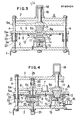
- Fig. 3 is a sectional view taken on line III-III of Fig. 1.
- Fig. 4 is a longitudinal sectional side view when the mold is closed.
- Fig. 5 is a longitudinal sectional side view of a stretching blow operating station during the stretching blow molding.
- Fig. 6 is a longitudinal sectional side view showing the operation of a removal operating station.
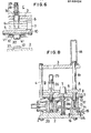
- Fig. 7 is the same longitudinal sectional side view as the aforesaid Fig. 1 in a second embodiment of the invention.
- Fig. 8 is likewise a longitudinal sectional side view when the mold is clsoed.
- In the drawings, a reference numeral 1 designates a machine bed, on which a
base 2 is fixed. Above thebase 2, atop plate 3 is connected to be positioned horizontally on thebase 2 by means of tie rods provided at three points on the peripheral edge. - Between the
base 2 and thetop plate 3, amovable plate 5 and aclamping plate 6 are disposed above and below, movably up and down and movably to and from each other withlugs tie rods - A
circular transfer plate 8 rotatable every angle of 120° is mounted on the undersurface of themovable plate 5 at the lower side of theclamping plate 6 movably by acentral shaft 10 while embracing the periphery thereof by amember 9, saidtransfer plate 8 being rotated by a hydraulically or electrically operateddrive device 7 secured to the central portion above themovable plate 5. The rotation of thetransfer plate 8 is effected by use of a can member provided on thedrive device 7 or a pin and arm member provided between theshaft 10 and thetransfer plate 8, though not shown. - Hold
molds 12 consisting ofsplit molds 11 mounted for opening and closing in a radial direction are positioned at three locations of the undersurface of thetransfer plate 8. Stopping positions of thehold plates 12 respectively serve as an injection operating station A, a stretching blow operating station B and a relasing operating station C. - On the
base 2 corresponding to the injection operating station A, aninjection cavity 13 is placed on abed seat 14, and thebed seat 14 is internally provided with ahot runner block 16 with the side of which aninjection device 15 is in nozzle touching. Above theinjection cavity 13, aninjection core 17 closed with thehold mold 12 and theinjection cavity 13 fromopenings movable plate 15 and thetransfer plate 8 is attached to the underside of theclamping plate 6. - A hydraulically-operated
clamping device 18 is provided on the upper side corresponding to theinjection cavity 13 of thetop plate 3, ana aclamping rod 19 downwardly extended while passing through thetop plate 3 from theclamping device 18 and theaforesaid clamping plate 6 are connected together. - While in this embodiment, the
clamping rod 19 is directly connected to theclamping plate 6, it should be noted that theclamping plate 6 and theclamping rod 19 can be connected through a crank device. In this case, a known crank device adapted to effect crank motion by a pinion and rack is mounted on theclamping plate 6 and the end of theclamping rod 19 can be connected to the crank device, though not shown. In this way, only theclamping plate 6 can be moved up and down by the expansion of the arm of the crank device, and theclamping rod 19 need not be moved up and down together with theclamping plate 6. If theclamping rod 19 is designed to be actuated when the arm is expanded, opening and clamping may be carried out at a high speed. - On the
base 2 corresponding to the stretching blow molding station B, ablow cavity 20 is connected to the upper end of apiston rod 22 from a pneumatically or hydraulically operatedlift 21 mounted on the underside of the base, saidblow cavity 20 being movable up and down. Above theblow cavity 20, ablow core 23 closed with thehold mold 12 and theblow cavity 20 fromopenings movable plate 5 and thetransfer plate 8 is attached to the underside of theclamping plate 6. - An expanding
device 25 for arod 24 which passes through theclamping plate 6 and theblow core 21 and extends into theblow cavity 20 is mounted on the upper side of theclamping plate 6, said extendingrod 24 being connected to the lower end of apiston rod 26 operated by air. - As shown in Fig. 6, a
guide hole 27 for a molded article is bored in thebase 2 corresponding to the removal operating station C, and a removingdevice 28 is mounted on the upperside of theclamping plate 6 corresponding to theguide hole 27. This removingdevice 28 comprises a pair of wedge-like opening plates 30 mounted on the lower end of apiston rod 29 operated by air, saidopening plates 30 passing through theclamping plate 6 and themovable plate 5 to radially push open thesplit molds 11 of thehold molds 12 to release molded articles held by thehold molds 12. - A
reference numeral 31 designates a returning device for themovable plate 5, the returning device comprising aflange 32 provided on thetie rod 4 and a coiledspring 33 in the periphery of the tie rod retained over theflange 32 and thelug 5a of themovable plate 5 to control the returning position by the engagement between the end of acover member 34 and theflange 32. - Figs. 7 and 8 illustrate a second embodiment of the present invention in which there is provided a pair of split molds adapted to radially open and close the
blow cavity 20, and the aforesaid returningdevice 31 comprises a pneumatically or hydraulically operatedcylinder 31a provided over thebase 2 and the central portion of thetransfer plate 8 and apiston rod 31b. Other parts in the second embodiment have the construction similar to those of the above-described first embodiment. - The operation of the first embodiment will be described hereinafter in an orderly manner.
- First, in the opened state shown in Figs. 2, 3 and 6, when the
clamping device 18 is actuated to extend theclamping rod 19 downwardly, theclamping plate 6 is pressed downwardly to be moved and comes into contact with the upperside of tehmovable plate 5. Thereby, both theinjection core 17 and theblow core 23 respectively fit in thehold molds 12 from theopenings movable plate 5 and thetransfer plate 8. - When the
clamping rod 19 is further extended, themovable plate 5 is pressed by theclamping plate 6 and moved downwardly while compressing thecoiled spring 33. It is noted that in the second embodiment, the the movable plate is moved while pressing thepiston rod 31b. - In the removal operating station C, the
opening plate 30 positioned as shown in Fig. 7 moves down along with the clamping plate and fits into aslot 5d (see Fig. 1) of themovable plate 5 shown in Fig. 1. - The downward movement of the
movable plate 5 stops at the position where thehold molds 12 and theinjection cavity 13 andblow cavity 20 are closed. - In the injection operating station A, molding of a
preform 40 is accomplished, and in the stretching blow operating station B, as shown in Fig. 5, the expandingdevice 25 is actuated and thepreform 40 is stretched axially by the extendingrod 24 and air is blown from theblow core 23 to form thepreform 40. - In the removal operating station C, as shown in Fig. 6, the removing
device 28 is actuated, and the openingplate 30 is forced into a parting line of thesplit mold 11 of thehold mold 12 to push open thesplit mold 11 in a radial direction to release the moldedarticle 41 from thehold mold 12. - Upon completion of the molding as described above, the clamping
device 18 is actuated in a direction of opening to pull back the clampingrod 19 to its original position together with the clampingplate 6, then the pressing force relative to themovable plate 5 is released and themovable plate 5 is returned to its original position by the repulsion force of the coiledspring 33 which has been compressed, where opening occurs. The clampingplate 6 is further moved upwardly together with the clampingrod 19 whereby theinjection core 17 and theblow core 23 are moved upwardly of thehold mold 12 to render thetransfer plate 8 rotatable. In the second embodiment, thepiston rod 31b is extended upwardly to return the movable plate to its original position. - As a consequence, the
preform 40 is held by thehold mold 12 in the injection operating station A and the moldedarticle 41 is held by thehold mold 12 in the stretching blow operating station B, and they are fed to the succeeding operating station by the 120° rotation of tehtransfer plate 8. Then, the subsequent molding is carried out in a process similar to that as described above. - In the present invention, as will be apparent from the above-described embodiments, the
movable plate 5 provided at the underside with thetransfer plate 8 comprising a rotary disc and theclamping plate 6 connected with the clampingrod 19 placed on thetop plate 3 are disposed movably up and down with the returningdevices movable plate 5 between thebase 2 and thetop plate 3, and the injection and blowcavities base 2, and three molds, i.e., the hold sold 12 at the undersurface of the transfer plate and the injection and blowcores movable plate 5 and theclamping plate 6. With this arrangement, the injection cavity need not be moved up and down for the purpose of closing and theinjection device 15 may be always placed in nozzle touching, and no side run-out due to the side pressure during nozzle touching occurs to thereby prevent the preform from one-side wall thickness. - In addition, since the
movable plate 5 is moved up and down, no molding limit involves due to the dimension of height of the molded article, and in molding small bottles and the like, the injection mold needs not be raised, thus providing the general-purpose use. - Moreover, since the
transfer plate 8 is rotated after removal of thepreform 40 and moldedarticle 41 upwardly of the injection and blowcavities article 41 is prevented from impinging upon theblow cavity 20 to be damaged during the transfer. - Furthermore, since the
injection cavity 13 is placed on thebase 2, the clamping device on the side of the injection cavity and the hydraulic device associated therewith can be omitted, the cost can be advantageously saved through that portion.
Claims (6)
- (1) An injection stretching blow molding machine comprising a base secured onto a machine bed, a top plate positioned above said base and connected to said base by means of a plurality of tie rods in the peripheral edge, a movable plate slidably inserted through said tie rod and disposed movably up and down between the base and the top plate, a clamping plate above the movable plate, a transfer plate at the undersurface of said movable plate and rotable at predetermined intervals by a drive device provided in the central portion above the movable plate, the required number of hold molds consisting of split molds mounted on the undersurface of the transfer plate, said hold molds being opened and closed in a radial direction, an injection cavity and a blow cavity on the base closed in connection with said hold molds, an injection core and a blow core mounted at the lower side of said clamping plate and closed in connection with the hold molds from openings bored in the movable plate and the transfer plate, a stretching rod operating device and a releasing device provided above the clamping plate, and a clamping device provided above said top plate, said clamping device corresponding to the injection cavity, wherein a clamping rod of the clamping device and the clamping plate are connected, and a returning device is provided over the movable plate and the base or the tie rods.
- (2) The injection stretching blow molding machine as claimed in claim 1, wherein said returning device comprises a flange provided on the tie rod and a coiled spring in the periphery of the tie rod retained between the flange and the movable plate.
- (3) The injection stretching blow molding machine as claimed in claim 1, wherein said returning device comprises a hydraulic cylinder provided between the base and the movable plate and a rod.
- (4) The injection stretching blow molding machine as claimed in claim 1, wherein said clamping plate and said clamping rod are connected through a crank device.
- (5) The injection stretching blow molding machine as claimed in claim 1, wherein said drive device is hydraulically or electrically operated.
- (6) The injection stretching blow molding machine as claimed in claim 1, wherein said drive device comprises means for rotating the transfer plate at predetermined intervals.
Applications Claiming Priority (2)
| Application Number | Priority Date | Filing Date | Title |
|---|---|---|---|
| JP100164/84 | 1984-05-18 | ||
| JP59100164A JPS60244518A (en) | 1984-05-18 | 1984-05-18 | Injection stretching blow molding machine |
Publications (3)
| Publication Number | Publication Date |
|---|---|
| EP0162424A2 true EP0162424A2 (en) | 1985-11-27 |
| EP0162424A3 EP0162424A3 (en) | 1986-10-08 |
| EP0162424B1 EP0162424B1 (en) | 1988-09-14 |
Family
ID=14266673
Family Applications (1)
| Application Number | Title | Priority Date | Filing Date |
|---|---|---|---|
| EP85106082A Expired EP0162424B1 (en) | 1984-05-18 | 1985-05-17 | Injection stretching blow molding machine |
Country Status (7)
| Country | Link |
|---|---|
| US (1) | US4648824A (en) |
| EP (1) | EP0162424B1 (en) |
| JP (1) | JPS60244518A (en) |
| KR (1) | KR920002360B1 (en) |
| AU (1) | AU571331B2 (en) |
| CA (1) | CA1250111A (en) |
| DE (1) | DE3564915D1 (en) |
Cited By (8)
| Publication number | Priority date | Publication date | Assignee | Title |
|---|---|---|---|---|
| EP0228324A2 (en) * | 1985-11-29 | 1987-07-08 | Nissei Asb Machine Co., Ltd. | Mold device for molding a preform |
| EP0425388A2 (en) * | 1989-10-27 | 1991-05-02 | Nissei Asb Machine Co., Ltd. | Rotary type injection molding machine |
| EP0426096A2 (en) * | 1989-10-30 | 1991-05-08 | A.K. Technical Laboratory, Inc., | Rotary type injection orientation blow molding machine |
| EP0533437A2 (en) * | 1991-09-19 | 1993-03-24 | Toppan Printing Co., Ltd. | Method for producing a multilayered thin wall container and a multilayered thin wall container |
| EP0567163A2 (en) * | 1987-07-17 | 1993-10-27 | Nissei Asb Machine Co., Ltd. | Rotary type molding machine |
| EP0673748A1 (en) * | 1993-07-30 | 1995-09-27 | Nissei Asb Machine Co., Ltd. | Method of injection molding preform and apparatus therefor |
| EP0703058A3 (en) * | 1994-09-26 | 1997-04-16 | A K Tech Lab Inc | Blow molding device with two moulds whereby one is used for preforming and the other for final forming of large containers by the use of one closing device |
| CN106626270A (en) * | 2015-07-24 | 2017-05-10 | 苏州汉扬精密电子有限公司 | Sliding block structure of mold |
Families Citing this family (21)
| Publication number | Priority date | Publication date | Assignee | Title |
|---|---|---|---|---|
| JPH07108547B2 (en) * | 1986-10-31 | 1995-11-22 | 日精エ−・エス・ビ−機械株式会社 | Molding equipment for rotational molding machines |
| JPS60178020A (en) * | 1984-02-24 | 1985-09-12 | Katashi Aoki | Molding process of thin wall-vessel and mold device thereof |
| DE3686744T2 (en) * | 1985-06-14 | 1993-04-08 | Nissei Asb Machine Co Ltd | INJECTION STRETCH BLOW MOLDING MACHINE. |
| JP2536742B2 (en) * | 1986-11-05 | 1996-09-18 | 日精エ−・エス・ビ−機械株式会社 | Rotary injection blow molding machine |
| JPH069856B2 (en) * | 1987-04-20 | 1994-02-09 | 青木 茂人 | Rotary injection blow molding machine |
| JPH0694158B2 (en) * | 1990-10-26 | 1994-11-24 | 日精エー・エス・ビー機械株式会社 | Preform for molding a can body made of synthetic resin and method for manufacturing a can body made of synthetic resin using the same |
| JP2530398B2 (en) * | 1991-09-19 | 1996-09-04 | 日精エー・エス・ビー機械株式会社 | Injection stretch blow molding equipment |
| US5403177A (en) * | 1993-07-16 | 1995-04-04 | Jomar Corporation | Injection stretch blow molding machine |
| US5700496A (en) * | 1994-11-15 | 1997-12-23 | Bacon; Charles R. | Self-adjusting mold backplate |
| DE19506599C2 (en) * | 1995-02-24 | 1998-08-13 | Knauer Systec Eng Gmbh | Injection molding machine |
| US5569473A (en) * | 1995-05-23 | 1996-10-29 | Electra Form, Inc. | Apparatus for forming a recyclable lined container |
| TW289008B (en) * | 1995-07-18 | 1996-10-21 | A K Tech Lab Inc | Air operation method and device for an extention blow forming machine |
| US5840349A (en) * | 1997-02-12 | 1998-11-24 | Graham Engineering Corporation | Rotary blow molding machine |
| JP2002103430A (en) * | 2000-09-29 | 2002-04-09 | Aoki Technical Laboratory Inc | Rotary transfer apparatus in blow molding machine |
| JP4739933B2 (en) * | 2005-11-30 | 2011-08-03 | 株式会社青木固研究所 | Injection stretch blow molding machine |
| JP4791182B2 (en) * | 2005-12-29 | 2011-10-12 | 日精エー・エス・ビー機械株式会社 | Injection blow molding machine |
| JP4837442B2 (en) * | 2006-05-30 | 2011-12-14 | 株式会社青木固研究所 | Injection stretch blow molding machine |
| ITBI20080006A1 (en) * | 2008-04-24 | 2009-10-25 | Thermoplay Spa | INJECTION MOLDING SYSTEM OF PLASTIC MATERIALS, PARTICULARLY SUITABLE FOR ASSOCIATION WITH A BLOWING UNIT OF PRINTED PLASTIC MATERIAL. |
| JP5798440B2 (en) * | 2011-10-18 | 2015-10-21 | 日精エー・エス・ビー機械株式会社 | Blow mold unit and blow molding machine using the same |
| CN104175530A (en) * | 2014-04-04 | 2014-12-03 | 林玉斋 | Multi-movable plate automatic bottle making machine |
| CN114147941B (en) * | 2021-11-30 | 2023-12-08 | 优之科技(深圳)有限公司 | Blow molding polishing treatment system |
Citations (7)
| Publication number | Priority date | Publication date | Assignee | Title |
|---|---|---|---|---|
| DE2006258A1 (en) * | 1969-03-01 | 1970-10-22 | International Press Development Etablishement, Vaduz | Injection and blow molding machine for the continuous production of hollow bodies from plastic material |
| FR2098332A1 (en) * | 1970-07-10 | 1972-03-10 | Showa Denko Kk | |
| FR2169377A1 (en) * | 1972-01-29 | 1973-09-07 | Nissei Plastics Ind Co | |
| US3990826A (en) * | 1973-12-27 | 1976-11-09 | Paul Marcus | Injection blow molding apparatus |
| FR2343586A1 (en) * | 1976-03-12 | 1977-10-07 | Katashi Aoki | INJECTION AND BLOW MOLDING MACHINE |
| FR2409846A1 (en) * | 1977-11-24 | 1979-06-22 | Hercules Inc | Injection blow moulding machine - with non-split moulds and movable mandrels carrying neck forming moulds |
| GB2094220A (en) * | 1981-02-03 | 1982-09-15 | Katashi Aoki | Injection stretching and blow moulding machine |
Family Cites Families (3)
| Publication number | Priority date | Publication date | Assignee | Title |
|---|---|---|---|---|
| OA00221A (en) * | 1963-11-21 | 1966-03-15 | Settembrini Antoine Di | Machine for the manufacture of plastic containers. |
| US4224263A (en) * | 1978-03-14 | 1980-09-23 | Owens-Illinois, Inc. | Method for blow molding |
| JPS57150542A (en) * | 1981-03-13 | 1982-09-17 | Katashi Aoki | Injection, stretching, and blow molding machine |
-
1984
- 1984-05-18 JP JP59100164A patent/JPS60244518A/en active Granted
-
1985
- 1985-05-15 AU AU42505/85A patent/AU571331B2/en not_active Expired
- 1985-05-15 US US06/734,069 patent/US4648824A/en not_active Expired - Lifetime
- 1985-05-17 DE DE8585106082T patent/DE3564915D1/en not_active Expired
- 1985-05-17 EP EP85106082A patent/EP0162424B1/en not_active Expired
- 1985-05-17 CA CA000481740A patent/CA1250111A/en not_active Expired
- 1985-05-18 KR KR1019850003412A patent/KR920002360B1/en not_active IP Right Cessation
Patent Citations (7)
| Publication number | Priority date | Publication date | Assignee | Title |
|---|---|---|---|---|
| DE2006258A1 (en) * | 1969-03-01 | 1970-10-22 | International Press Development Etablishement, Vaduz | Injection and blow molding machine for the continuous production of hollow bodies from plastic material |
| FR2098332A1 (en) * | 1970-07-10 | 1972-03-10 | Showa Denko Kk | |
| FR2169377A1 (en) * | 1972-01-29 | 1973-09-07 | Nissei Plastics Ind Co | |
| US3990826A (en) * | 1973-12-27 | 1976-11-09 | Paul Marcus | Injection blow molding apparatus |
| FR2343586A1 (en) * | 1976-03-12 | 1977-10-07 | Katashi Aoki | INJECTION AND BLOW MOLDING MACHINE |
| FR2409846A1 (en) * | 1977-11-24 | 1979-06-22 | Hercules Inc | Injection blow moulding machine - with non-split moulds and movable mandrels carrying neck forming moulds |
| GB2094220A (en) * | 1981-02-03 | 1982-09-15 | Katashi Aoki | Injection stretching and blow moulding machine |
Cited By (15)
| Publication number | Priority date | Publication date | Assignee | Title |
|---|---|---|---|---|
| EP0228324A3 (en) * | 1985-11-29 | 1989-01-18 | Nissei Asb Machine Co., Ltd. | Mold device for molding a preform |
| EP0228324A2 (en) * | 1985-11-29 | 1987-07-08 | Nissei Asb Machine Co., Ltd. | Mold device for molding a preform |
| EP0567163A2 (en) * | 1987-07-17 | 1993-10-27 | Nissei Asb Machine Co., Ltd. | Rotary type molding machine |
| EP0567163A3 (en) * | 1987-07-17 | 1993-11-10 | Nissei Asb Machine Co Ltd | Rotary type molding machine |
| EP0425388A2 (en) * | 1989-10-27 | 1991-05-02 | Nissei Asb Machine Co., Ltd. | Rotary type injection molding machine |
| EP0425388A3 (en) * | 1989-10-27 | 1991-08-21 | Nissei Asb Machine Co., Ltd. | Rotary type injection molding machine |
| EP0426096A2 (en) * | 1989-10-30 | 1991-05-08 | A.K. Technical Laboratory, Inc., | Rotary type injection orientation blow molding machine |
| EP0426096A3 (en) * | 1989-10-30 | 1992-01-15 | A K Tech Lab Inc | Rotary type injection orientation blow molding machine |
| EP0533437A3 (en) * | 1991-09-19 | 1993-05-26 | Toppan Printing Co., Ltd. | Method for producing a multilayered thin wall container and a multilayered thin wall container |
| EP0533437A2 (en) * | 1991-09-19 | 1993-03-24 | Toppan Printing Co., Ltd. | Method for producing a multilayered thin wall container and a multilayered thin wall container |
| EP0673748A1 (en) * | 1993-07-30 | 1995-09-27 | Nissei Asb Machine Co., Ltd. | Method of injection molding preform and apparatus therefor |
| EP0673748A4 (en) * | 1993-07-30 | 1996-09-04 | Nissei Asb Machine Co Ltd | Method of injection molding preform and apparatus therefor. |
| US5589130A (en) * | 1993-07-30 | 1996-12-31 | Nissei Asb Machine Co., Ltd. | Method of injection molding a preform and apparatus for the same |
| EP0703058A3 (en) * | 1994-09-26 | 1997-04-16 | A K Tech Lab Inc | Blow molding device with two moulds whereby one is used for preforming and the other for final forming of large containers by the use of one closing device |
| CN106626270A (en) * | 2015-07-24 | 2017-05-10 | 苏州汉扬精密电子有限公司 | Sliding block structure of mold |
Also Published As
| Publication number | Publication date |
|---|---|
| KR920002360B1 (en) | 1992-03-23 |
| CA1250111A (en) | 1989-02-21 |
| AU571331B2 (en) | 1988-04-14 |
| KR850008287A (en) | 1985-12-16 |
| DE3564915D1 (en) | 1988-10-20 |
| JPH0447609B2 (en) | 1992-08-04 |
| US4648824A (en) | 1987-03-10 |
| AU4250585A (en) | 1985-11-21 |
| EP0162424A3 (en) | 1986-10-08 |
| EP0162424B1 (en) | 1988-09-14 |
| JPS60244518A (en) | 1985-12-04 |
Similar Documents
| Publication | Publication Date | Title |
|---|---|---|
| EP0162424B1 (en) | Injection stretching blow molding machine | |
| USRE32129E (en) | Injection blow molding machine | |
| CA1179811A (en) | Injection stretching blow molding machine | |
| US7128865B2 (en) | Apparatus and method for two stage ejection of a molded preform from a mold | |
| US4422843A (en) | Injection stretching blow molding machine | |
| US3624672A (en) | Molding of cellular objects | |
| CA2234879A1 (en) | Ejection methods and linkage apparatus for stack molds | |
| US4946367A (en) | Rotary type blow molding machine | |
| EP0228324B1 (en) | Mold device for molding a preform | |
| JPS61287715A (en) | Injecting, drawing and blow molding machine | |
| EP0425388B1 (en) | Rotary type injection molding machine | |
| US4846661A (en) | Rotary type injection blow molding machine | |
| JP2901837B2 (en) | Vertical injection molding machine | |
| JPS63171242A (en) | Mold for forming impeller blade type rotary body | |
| KR960013618A (en) | Method and apparatus for manufacturing expandable plastic product | |
| US4080146A (en) | Segmented blow molds | |
| JP3326039B2 (en) | Continuous molding equipment for resin molded products | |
| US3860377A (en) | An injection-blow molding apparatus including product ejector means | |
| SU1692854A1 (en) | Mould for making polymer articles | |
| JPH11333849A (en) | Mold device for molding multiple materials and method for molding multiple materials used therewith | |
| SU1685734A1 (en) | Machine for processing thermoplastic materials | |
| JPH0523166B2 (en) | ||
| JPH06134768A (en) | Undercut processing mold | |
| JPH0532211B2 (en) | ||
| JPH07108547B2 (en) | Molding equipment for rotational molding machines |
Legal Events
| Date | Code | Title | Description |
|---|---|---|---|
| PUAI | Public reference made under article 153(3) epc to a published international application that has entered the european phase |
Free format text: ORIGINAL CODE: 0009012 |
|
| AK | Designated contracting states |
Designated state(s): DE FR IT NL |
|
| PUAL | Search report despatched |
Free format text: ORIGINAL CODE: 0009013 |
|
| AK | Designated contracting states |
Kind code of ref document: A3 Designated state(s): DE FR IT NL |
|
| 17P | Request for examination filed |
Effective date: 19861113 |
|
| 17Q | First examination report despatched |
Effective date: 19870629 |
|
| GRAA | (expected) grant |
Free format text: ORIGINAL CODE: 0009210 |
|
| AK | Designated contracting states |
Kind code of ref document: B1 Designated state(s): DE FR IT NL |
|
| ITF | It: translation for a ep patent filed |
Owner name: JACOBACCI & PERANI S.P.A. |
|
| REF | Corresponds to: |
Ref document number: 3564915 Country of ref document: DE Date of ref document: 19881020 |
|
| ET | Fr: translation filed | ||
| PLBE | No opposition filed within time limit |
Free format text: ORIGINAL CODE: 0009261 |
|
| STAA | Information on the status of an ep patent application or granted ep patent |
Free format text: STATUS: NO OPPOSITION FILED WITHIN TIME LIMIT |
|
| 26N | No opposition filed | ||
| ITTA | It: last paid annual fee | ||
| PGFP | Annual fee paid to national office [announced via postgrant information from national office to epo] |
Ref country code: DE Payment date: 20040410 Year of fee payment: 20 |
|
| PGFP | Annual fee paid to national office [announced via postgrant information from national office to epo] |
Ref country code: NL Payment date: 20040518 Year of fee payment: 20 |
|
| PGFP | Annual fee paid to national office [announced via postgrant information from national office to epo] |
Ref country code: FR Payment date: 20040519 Year of fee payment: 20 |
|
| PG25 | Lapsed in a contracting state [announced via postgrant information from national office to epo] |
Ref country code: NL Free format text: LAPSE BECAUSE OF EXPIRATION OF PROTECTION Effective date: 20050517 |
|
| NLV7 | Nl: ceased due to reaching the maximum lifetime of a patent |
Effective date: 20050517 |