US4946367A - Rotary type blow molding machine - Google Patents

Rotary type blow molding machine Download PDF

Info

Publication number
US4946367A
US4946367A US07/350,749 US35074989A US4946367A US 4946367 A US4946367 A US 4946367A US 35074989 A US35074989 A US 35074989A US 4946367 A US4946367 A US 4946367A
Authority
US
United States
Prior art keywords
molding machine
transfer plate
piston
machine
mold
Prior art date
Legal status (The legal status is an assumption and is not a legal conclusion. Google has not performed a legal analysis and makes no representation as to the accuracy of the status listed.)
Expired - Lifetime
Application number
US07/350,749
Inventor
Yoshinori Nakamura
Current Assignee (The listed assignees may be inaccurate. Google has not performed a legal analysis and makes no representation or warranty as to the accuracy of the list.)
Nissei ASB Machine Co Ltd
Original Assignee
Nissei ASB Machine Co Ltd
Priority date (The priority date is an assumption and is not a legal conclusion. Google has not performed a legal analysis and makes no representation as to the accuracy of the date listed.)
Filing date
Publication date
Application filed by Nissei ASB Machine Co Ltd filed Critical Nissei ASB Machine Co Ltd
Assigned to NISSEI ASB MACHINE CO., LTD., A CO. OF JAPAN reassignment NISSEI ASB MACHINE CO., LTD., A CO. OF JAPAN ASSIGNMENT OF ASSIGNORS INTEREST. Assignors: NAKAMURA, YOSHINORI
Application granted granted Critical
Publication of US4946367A publication Critical patent/US4946367A/en
Anticipated expiration legal-status Critical
Expired - Lifetime legal-status Critical Current

Links

Images

Classifications

    • BPERFORMING OPERATIONS; TRANSPORTING
    • B29WORKING OF PLASTICS; WORKING OF SUBSTANCES IN A PLASTIC STATE IN GENERAL
    • B29CSHAPING OR JOINING OF PLASTICS; SHAPING OF MATERIAL IN A PLASTIC STATE, NOT OTHERWISE PROVIDED FOR; AFTER-TREATMENT OF THE SHAPED PRODUCTS, e.g. REPAIRING
    • B29C49/00Blow-moulding, i.e. blowing a preform or parison to a desired shape within a mould; Apparatus therefor
    • B29C49/02Combined blow-moulding and manufacture of the preform or the parison
    • B29C49/06Injection blow-moulding
    • B29C49/061Injection blow-moulding with parison holding means displaceable between injection and blow stations
    • B29C49/062Injection blow-moulding with parison holding means displaceable between injection and blow stations following an arcuate path, e.g. rotary or oscillating-type
    • BPERFORMING OPERATIONS; TRANSPORTING
    • B29WORKING OF PLASTICS; WORKING OF SUBSTANCES IN A PLASTIC STATE IN GENERAL
    • B29CSHAPING OR JOINING OF PLASTICS; SHAPING OF MATERIAL IN A PLASTIC STATE, NOT OTHERWISE PROVIDED FOR; AFTER-TREATMENT OF THE SHAPED PRODUCTS, e.g. REPAIRING
    • B29C49/00Blow-moulding, i.e. blowing a preform or parison to a desired shape within a mould; Apparatus therefor
    • B29C49/02Combined blow-moulding and manufacture of the preform or the parison
    • B29C2049/023Combined blow-moulding and manufacture of the preform or the parison using inherent heat of the preform, i.e. 1 step blow moulding
    • BPERFORMING OPERATIONS; TRANSPORTING
    • B29WORKING OF PLASTICS; WORKING OF SUBSTANCES IN A PLASTIC STATE IN GENERAL
    • B29CSHAPING OR JOINING OF PLASTICS; SHAPING OF MATERIAL IN A PLASTIC STATE, NOT OTHERWISE PROVIDED FOR; AFTER-TREATMENT OF THE SHAPED PRODUCTS, e.g. REPAIRING
    • B29C2949/00Indexing scheme relating to blow-moulding
    • B29C2949/07Preforms or parisons characterised by their configuration
    • B29C2949/0715Preforms or parisons characterised by their configuration the preform having one end closed
    • BPERFORMING OPERATIONS; TRANSPORTING
    • B29WORKING OF PLASTICS; WORKING OF SUBSTANCES IN A PLASTIC STATE IN GENERAL
    • B29CSHAPING OR JOINING OF PLASTICS; SHAPING OF MATERIAL IN A PLASTIC STATE, NOT OTHERWISE PROVIDED FOR; AFTER-TREATMENT OF THE SHAPED PRODUCTS, e.g. REPAIRING
    • B29C49/00Blow-moulding, i.e. blowing a preform or parison to a desired shape within a mould; Apparatus therefor
    • B29C49/02Combined blow-moulding and manufacture of the preform or the parison
    • B29C49/06Injection blow-moulding
    • BPERFORMING OPERATIONS; TRANSPORTING
    • B29WORKING OF PLASTICS; WORKING OF SUBSTANCES IN A PLASTIC STATE IN GENERAL
    • B29CSHAPING OR JOINING OF PLASTICS; SHAPING OF MATERIAL IN A PLASTIC STATE, NOT OTHERWISE PROVIDED FOR; AFTER-TREATMENT OF THE SHAPED PRODUCTS, e.g. REPAIRING
    • B29C49/00Blow-moulding, i.e. blowing a preform or parison to a desired shape within a mould; Apparatus therefor
    • B29C49/42Component parts, details or accessories; Auxiliary operations
    • B29C49/4205Handling means, e.g. transfer, loading or discharging means
    • B29C49/42073Grippers
    • B29C49/42087Grippers holding outside the neck
    • BPERFORMING OPERATIONS; TRANSPORTING
    • B29WORKING OF PLASTICS; WORKING OF SUBSTANCES IN A PLASTIC STATE IN GENERAL
    • B29CSHAPING OR JOINING OF PLASTICS; SHAPING OF MATERIAL IN A PLASTIC STATE, NOT OTHERWISE PROVIDED FOR; AFTER-TREATMENT OF THE SHAPED PRODUCTS, e.g. REPAIRING
    • B29C49/00Blow-moulding, i.e. blowing a preform or parison to a desired shape within a mould; Apparatus therefor
    • B29C49/42Component parts, details or accessories; Auxiliary operations
    • B29C49/64Heating or cooling preforms, parisons or blown articles
    • B29C49/6409Thermal conditioning of preforms
    • B29C49/6427Cooling of preforms
    • BPERFORMING OPERATIONS; TRANSPORTING
    • B29WORKING OF PLASTICS; WORKING OF SUBSTANCES IN A PLASTIC STATE IN GENERAL
    • B29CSHAPING OR JOINING OF PLASTICS; SHAPING OF MATERIAL IN A PLASTIC STATE, NOT OTHERWISE PROVIDED FOR; AFTER-TREATMENT OF THE SHAPED PRODUCTS, e.g. REPAIRING
    • B29C49/00Blow-moulding, i.e. blowing a preform or parison to a desired shape within a mould; Apparatus therefor
    • B29C49/42Component parts, details or accessories; Auxiliary operations
    • B29C49/64Heating or cooling preforms, parisons or blown articles
    • B29C49/6604Thermal conditioning of the blown article
    • B29C49/6605Heating the article, e.g. for hot fill
    • BPERFORMING OPERATIONS; TRANSPORTING
    • B29WORKING OF PLASTICS; WORKING OF SUBSTANCES IN A PLASTIC STATE IN GENERAL
    • B29CSHAPING OR JOINING OF PLASTICS; SHAPING OF MATERIAL IN A PLASTIC STATE, NOT OTHERWISE PROVIDED FOR; AFTER-TREATMENT OF THE SHAPED PRODUCTS, e.g. REPAIRING
    • B29C49/00Blow-moulding, i.e. blowing a preform or parison to a desired shape within a mould; Apparatus therefor
    • B29C49/42Component parts, details or accessories; Auxiliary operations
    • B29C49/64Heating or cooling preforms, parisons or blown articles
    • B29C49/68Ovens specially adapted for heating preforms or parisons
    • B29C49/681Ovens specially adapted for heating preforms or parisons using a conditioning receptacle, e.g. a cavity, e.g. having heated or cooled regions

Definitions

  • This invention relates to a rotary type molding machine which can be utilized for continuous molding of a preform or in situations where molding of a preform followed by orientation blow molding of a hollow molded product are continuously carried out.
  • a rotary molding machine of the type described herein includes one configuration which has a construction in which a base plate is secured upwardly relative to a machine bed, and an injection molding device which is movable up and down with respect to a transfer plate provided intermittently and rotatably on the underside of the base plate.
  • the injection molding device is movable up and down to effect a clamping action.
  • the other configuration has a construction in which an injection molding device is secured on one side thereof to one side of a machine bed, a base plate side is disposed movably up and down in opposed relation thereto, and a rotary plate is movable down together with the base plate to effect clamping.
  • the first machine configuration in which the base plate and the transfer plate are fixed has problems that since the injection mold device is moved up and down an every injection molding of a preform, an injection nozzle needs to be separated every time and therefore starting of measurement of resins material is delayed; and drooling or wire-drawing occurs every time the injection nozzle is separated, to a degree which depends on the type of resin. As a result, marginal portions of the injection nozzle or mold gate become stained and in addition a sprue gate is damaged by the resins adhered to the injection nozzle.
  • the second machine configuration in which the base plate side is moved up and down, has been developed in order to solve such problems.
  • this molding machine involves the problem that the transfer plate, the driving device therefor and various other devices required for molding are also moved up and down together with the base plate. Therefore, the weight which has to be moved vertically is large and as the molding machine becomes large in size, the vertical moving speed is restricted, making it difficult to open and close the lip mold at high speed. Particularly, when the vertically-moving stroke increases, the downwardly moving speed is accelerated so that the lip mold collides with the mold, thus requiring a buffer means.
  • An improved injection orientation blow molding machine for hollow molded products, e.g. bottles, which are longitudinally long has been needed for some time.
  • An object of the present invention is to provide a new rotary type molding machine in which an injection mold is secured to a machine bed side so that an injection device may be always placed in nozzle contact position to effect molding, the vertically-movable weight reduced, and a vertically-moving speed not accelerated due to a load.
  • an injection device may be always placed in nozzle contact position to effect molding, the vertically-movable weight reduced, and a vertically-moving speed not accelerated due to a load.
  • Another object of this invention is to provide a new rotary type molding machine in which both vertically-moving cylinder and driving device are positioned in the center of rotation of a moving plate, making it difficult to cause an unbalanced load, an eccentricity or like conditions. Also despite the use of the machine for long periods of time, the transfer plate is not inclined to impair rotation and a deviation in mold opening and closing will not occur.
  • the present invention provides a rotary type molding machine in which lip molds, which also serve as holders for a preform and a hollow molded product are provided on at least four portions in the underside of the rotatable element.
  • a circular transfer plate having a member receiving hole is provided on the surface on the lip molds above a machine bed supporting a central portion of a plate body by a rotary shaft.
  • the lip molds have stop positions set to an injection molding operation portion, a temperature control operation portion, an orientation blow molding operation portion and a molded product removing operation portion in that order. Molds and various devices are so disposed, that the rotary shaft of the transfer plate is constituted by a piston of a vertically-moving cylinder.
  • the piston and a driving shaft of an intermittently rotating driving device are connected freely with respect to an axial direction, and the transfer plate is provided so that it is movable up and down and intermittently rotatable with respect to the molds by the piston.
  • the aforesaid vertically-moving cylinder comprises a hydraulic cylinder installed on a support body disposed above the machine bed or the base plate provided on the machine bed, and a hydraulic oscillating motor.
  • a servo motor or the like, as an intermittently rotating driving device, is provided on the upper end or lower end of the first mentioned hydraulic cylinder.
  • the support body is not limited to a plate-like body but may be a frame mounted over tie bars standing upright in the periphery of the machine bed.
  • the piston for the vertically-moving cylinder serve as a rotary shaft and the driving shaft for the driving device are connected through a spline, the piston being rotated along with the driving shaft but only the piston is moved in an axial direction and moved up and down along with the transfer plate.
  • the aforementioned injection molding operation portion is equipped with an injection mold but the mold in the orientation blow molding operation portion is changed to a cooling mold when the rotary molding machine is used for continuous molding of a preform.
  • the transfer plate When the piston is contracted, the transfer plate is moved upward or downward so that the lip molds are separated from the mold, whereby they standby at a fixed level position. In such state, when the driving device is operated, the piston along with the driving shaft are rotated through the spline. Thereby, the transfer plate at the end of the piston also rotates so that the preform or molded product held by the lip mold rotates to the succeeding operation portion and stops.
  • FIG. 1 is a longitudinal sectional side view when mold is opened in a first embodiment
  • FIG. 2 is a longitudinal sectional side view when mold is closed
  • FIG. 3 is a partly cutaway plan view
  • FIG. 4 is a longitudinal sectional view when the mold is opened in a further embodiment.
  • FIG. 5 is a plan view.
  • the drawings illustrates a rotary type molding machine in the case of carrying out injection orientation blow molding.
  • FIGS. 1 and 2 respectively show longitudinal sectional side views of an injection molding operation portion and an orientation blow molding operation portion which are positioned opposite one another.
  • Tie bars 2, 2 stand upright at four locations in the periphery of a machine bed 1.
  • a plate-like support body 3 is horizontally secured to the tie bars 2, 2 in fixed spaced relation to a flat base plate 4 on the machine bed.
  • a hydraulically-operated vertically-moving cylinder 5 is longitudinally provided in the central portion of the support body 3, and an intermittently rotating driving device 6 in the form of a hydraulic oscillation motor whose rotational angle is 90° is connected to the top of the vertically-moving cylinder 5.
  • a driving shaft 7 of the driving device 6 is inserted into a piston 8 of the vertically moving cylinder 5 and connected to the piston 8 by way of a spline 9.
  • a central portion of a transfer plate 10 is connected to the lower end of the piston 8 whereby the transfer plate 10 is movable up and down by the vertically-moving cylinder 5 and is intermittently rotatable by angles of 90° by the driving device 7.
  • a working space is formed between the transfer plate 10 and the machine bed 1 for utilization similar to the conventional molding machine of this kind, and four portions are utilized as an injection molding operation portion, a temperature control operation portion, an orientation blow molding operation portion and a molded production removing operation portion, respectively.
  • a clamping device 11 in the form of a hyraulic cylinder is fixedly provided on the tie bars 2 and 12, and a temperature control device 25, an orientation blowing device 13 and a molded product removing device 26 are provided on the respective operation portions of the support body 3.
  • a temperature control device 25 an orientation blowing device 13 and a molded product removing device 26 are provided on the respective operation portions of the support body 3.
  • an air cylinder for vertically moving members to be operated or the like is provided on each of these devices similarly to prior art devices.
  • an injection mold 15 provided at its lower part with a hot runner block 14 is uprightly secured onto the base plate 4 of the injection molding operation portion, and a blow mold 16 is provided on the base plate 4 of the orientation blow molding operation portion so that it may be laterally opened and closed by hydraulically-operated opening and closing cylinders 17 and 17.
  • lip molds 18 and 18 for closing both the molds 15 and 16 are provided in a fixed spaced relation in the periphery of the lower surface of the transfer plate 10, and an injection core 20 and a blow core 21 at the end of a clamping member 19 are inserted into the lip molds 18 and 18 while extending through the member receiving holes 3a and 10a from the support body 3 and the transfer plate 3.
  • the resin is poured into the injection cavity 15a from the injection device 23 to mold the preform 22, and in the orientation blow molding operation portion, the preform 22 is axially oriented and expanded to the mold surface of the blow cavity 16a by blowing compressed air to mold a hollow product 24.
  • the clamping device 11 and the orientation blowing device 13 are moved upwardly and returned to their original position, and the blow mold 16 is opened.
  • the transfer plate 10 is returned to the original position in a state wherein the preform 22 and the molded product 24 are held on the lip molds 18 and 18.
  • the transfer plate 10 also rotates along with the piston 9 through 90° to transfer the lip molds 18 and 18 to the succeeding operation portion.
  • the vertically movable cylinder 5 is installed on the base plate 4 on the machine bed 1, in which case the driving device 6 is also mounted superposed to the lower end of the vertically-moving cylinder 5 with the driving shaft 7 having the spline 9 in the periphery thereof upwardly.
  • the support body in the aforesaid embodiment can be simplified, and the orientation blowing device 13, the temperature control device 25, the molded product removing device 26 and the like installed on the support body are individually independently instlled on the base plate 4 so that they may be moved up and down by the hydraulic cylinder 27.
  • the transfer plate 10 is moved upward by extending of the piston and is moved downward by contracting it.
  • Another embodiment is operated in a manner similar to that of the previous embodiment except as noted above, and will not be further described with other parts indicated by the same reference numerals in the drawings.
  • the rotary type molding machine can be also utilized as a continuous injection molding machine for a preform.
  • a blow molding device and a blow mold device are merely changed to a preform cooling device and a cooling mold device, though not shown in the drawings.
  • rotational angle is not limited to 90°. Rotational angles of 120°, 180° or the like can be used according to the number of the molding operation portions present.
  • the rotational shaft of the transfer plate is constituted by the piston for the vertically-moving cylinder, the piston and the driving shaft of the intermittently rotating driving device are freely connected with respect to the axial direction, and the transfer plate is provided so that the latter may be moved up and down and provided rotatably intermittently with respect to the molds. Therefore, the injection device can be always placed in nozzle contact with the injection mold secured to the machine bed for effecting molding.

Landscapes

  • Engineering & Computer Science (AREA)
  • Manufacturing & Machinery (AREA)
  • Mechanical Engineering (AREA)
  • Blow-Moulding Or Thermoforming Of Plastics Or The Like (AREA)

Abstract

A rotary type molding machine for molding preforms and hollow molded products from the preforms includes a circular transfer plate with depending lip molds. The transfer plate is disposed above a machine bed and is suspended from a plate body which is itself supported at its edges on the machine bed. The transfer plate is rotatable and movable up and down. Rotation of the transfer plate enables the lip molds to be aligned to one or the other of an injection molding station, a temperature control station, an orientation blow molding station, and a molded product moving station. Molds and various related devices are disposed on the machine bed. The transfer plate is reciprocated by a vertically movable piston and its hydraulic cylinder. The piston is flexibly coupled to a driving shaft of an intermittently rotatable driving device which shaft is effective to rotate the transfer plate and remain coupled to the piston regardless of the vertical position thereof.

Description

TECHNICAL FIELD
This invention relates to a rotary type molding machine which can be utilized for continuous molding of a preform or in situations where molding of a preform followed by orientation blow molding of a hollow molded product are continuously carried out.
BACKGROUND OF ART
A rotary molding machine of the type described herein includes one configuration which has a construction in which a base plate is secured upwardly relative to a machine bed, and an injection molding device which is movable up and down with respect to a transfer plate provided intermittently and rotatably on the underside of the base plate. The injection molding device is movable up and down to effect a clamping action. The other configuration has a construction in which an injection molding device is secured on one side thereof to one side of a machine bed, a base plate side is disposed movably up and down in opposed relation thereto, and a rotary plate is movable down together with the base plate to effect clamping.
The first machine configuration in which the base plate and the transfer plate are fixed has problems that since the injection mold device is moved up and down an every injection molding of a preform, an injection nozzle needs to be separated every time and therefore starting of measurement of resins material is delayed; and drooling or wire-drawing occurs every time the injection nozzle is separated, to a degree which depends on the type of resin. As a result, marginal portions of the injection nozzle or mold gate become stained and in addition a sprue gate is damaged by the resins adhered to the injection nozzle.
The second machine configuration, in which the base plate side is moved up and down, has been developed in order to solve such problems. However, this molding machine involves the problem that the transfer plate, the driving device therefor and various other devices required for molding are also moved up and down together with the base plate. Therefore, the weight which has to be moved vertically is large and as the molding machine becomes large in size, the vertical moving speed is restricted, making it difficult to open and close the lip mold at high speed. Particularly, when the vertically-moving stroke increases, the downwardly moving speed is accelerated so that the lip mold collides with the mold, thus requiring a buffer means. An improved injection orientation blow molding machine for hollow molded products, e.g. bottles, which are longitudinally long has been needed for some time.
SUMMARY OF THE INVENTION
This invention has been made in view of the above-described circumstances and problems. An object of the present invention is to provide a new rotary type molding machine in which an injection mold is secured to a machine bed side so that an injection device may be always placed in nozzle contact position to effect molding, the vertically-movable weight reduced, and a vertically-moving speed not accelerated due to a load. In accordance with the present invention, even if the verticall-moving stroke is large, opening and closing of a lip mold at a high speed can be carried out smoothly.
Another object of this invention is to provide a new rotary type molding machine in which both vertically-moving cylinder and driving device are positioned in the center of rotation of a moving plate, making it difficult to cause an unbalanced load, an eccentricity or like conditions. Also despite the use of the machine for long periods of time, the transfer plate is not inclined to impair rotation and a deviation in mold opening and closing will not occur.
For achieving the aforesaid objects, the present invention provides a rotary type molding machine in which lip molds, which also serve as holders for a preform and a hollow molded product are provided on at least four portions in the underside of the rotatable element. A circular transfer plate having a member receiving hole is provided on the surface on the lip molds above a machine bed supporting a central portion of a plate body by a rotary shaft. The lip molds have stop positions set to an injection molding operation portion, a temperature control operation portion, an orientation blow molding operation portion and a molded product removing operation portion in that order. Molds and various devices are so disposed, that the rotary shaft of the transfer plate is constituted by a piston of a vertically-moving cylinder. The piston and a driving shaft of an intermittently rotating driving device are connected freely with respect to an axial direction, and the transfer plate is provided so that it is movable up and down and intermittently rotatable with respect to the molds by the piston.
The aforesaid vertically-moving cylinder comprises a hydraulic cylinder installed on a support body disposed above the machine bed or the base plate provided on the machine bed, and a hydraulic oscillating motor. A servo motor or the like, as an intermittently rotating driving device, is provided on the upper end or lower end of the first mentioned hydraulic cylinder.
The support body is not limited to a plate-like body but may be a frame mounted over tie bars standing upright in the periphery of the machine bed. The piston for the vertically-moving cylinder serve as a rotary shaft and the driving shaft for the driving device are connected through a spline, the piston being rotated along with the driving shaft but only the piston is moved in an axial direction and moved up and down along with the transfer plate.
The aforementioned injection molding operation portion is equipped with an injection mold but the mold in the orientation blow molding operation portion is changed to a cooling mold when the rotary molding machine is used for continuous molding of a preform.
With the above-described structure, by the extension of the piston of the vertically-moving cylinder. The transfer plate is moved upward or downward so that the mold and lip molds are closed.
When the piston is contracted, the transfer plate is moved upward or downward so that the lip molds are separated from the mold, whereby they standby at a fixed level position. In such state, when the driving device is operated, the piston along with the driving shaft are rotated through the spline. Thereby, the transfer plate at the end of the piston also rotates so that the preform or molded product held by the lip mold rotates to the succeeding operation portion and stops.
BRIEF DESCRIPTION OF THE DRAWINGS
The drawings schematically show one embodiment of a rotary type molding machine according to this invention.
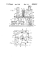
FIG. 1 is a longitudinal sectional side view when mold is opened in a first embodiment;
FIG. 2 is a longitudinal sectional side view when mold is closed;
FIG. 3 is a partly cutaway plan view;
FIG. 4 is a longitudinal sectional view when the mold is opened in a further embodiment; and
FIG. 5 is a plan view.
The drawings illustrates a rotary type molding machine in the case of carrying out injection orientation blow molding.
DETAILED DESCRIPTION OF THE INVENTION
FIGS. 1 and 2 respectively show longitudinal sectional side views of an injection molding operation portion and an orientation blow molding operation portion which are positioned opposite one another. Tie bars 2, 2 stand upright at four locations in the periphery of a machine bed 1. A plate-like support body 3 is horizontally secured to the tie bars 2, 2 in fixed spaced relation to a flat base plate 4 on the machine bed.
A hydraulically-operated vertically-moving cylinder 5 is longitudinally provided in the central portion of the support body 3, and an intermittently rotating driving device 6 in the form of a hydraulic oscillation motor whose rotational angle is 90° is connected to the top of the vertically-moving cylinder 5. A driving shaft 7 of the driving device 6 is inserted into a piston 8 of the vertically moving cylinder 5 and connected to the piston 8 by way of a spline 9.
A central portion of a transfer plate 10 is connected to the lower end of the piston 8 whereby the transfer plate 10 is movable up and down by the vertically-moving cylinder 5 and is intermittently rotatable by angles of 90° by the driving device 7.
A working space is formed between the transfer plate 10 and the machine bed 1 for utilization similar to the conventional molding machine of this kind, and four portions are utilized as an injection molding operation portion, a temperature control operation portion, an orientation blow molding operation portion and a molded production removing operation portion, respectively.
Above of the transfer plate of the injection molding operation portion, a clamping device 11 in the form of a hyraulic cylinder is fixedly provided on the tie bars 2 and 12, and a temperature control device 25, an orientation blowing device 13 and a molded product removing device 26 are provided on the respective operation portions of the support body 3. Although not shown, an air cylinder for vertically moving members to be operated or the like is provided on each of these devices similarly to prior art devices.
Furthermore, an injection mold 15 provided at its lower part with a hot runner block 14 is uprightly secured onto the base plate 4 of the injection molding operation portion, and a blow mold 16 is provided on the base plate 4 of the orientation blow molding operation portion so that it may be laterally opened and closed by hydraulically-operated opening and closing cylinders 17 and 17.
Four lip molds 18 and 18 for closing both the molds 15 and 16 are provided in a fixed spaced relation in the periphery of the lower surface of the transfer plate 10, and an injection core 20 and a blow core 21 at the end of a clamping member 19 are inserted into the lip molds 18 and 18 while extending through the member receiving holes 3a and 10a from the support body 3 and the transfer plate 3.
In the above-described rotary type molding machine, when the vertically-moving cylinder 5 is operated to extend the piston 8, the transfer plate 10 lowered from the support body side to the mold side, one lip mold 18 is closed in connection with the injection mold 15, the other lip mold 18 is closed in connection with the blow mold 16, and a preform 22 assumes a position of a blow cavity 16a. When the clamping device 11 and the orientation blowing device 13 are moved down after the mold has been closed, in the clamping device 11, the injection core 20 extends through the support body 3, the transfer plate 10 and the lip mold 18 and enters the injection cavity 15a, and the lower end of the clamping member 19 is pressed powerfully aginst the lip mold 18 whereby it is clamped thereagainst. In the orientation blowing device 3, the orientation blow core 21 is inserted into a lip portion of the preform 22 from the member receiving holes 3a and 10a.
In the injection molding operation portion, the resin is poured into the injection cavity 15a from the injection device 23 to mold the preform 22, and in the orientation blow molding operation portion, the preform 22 is axially oriented and expanded to the mold surface of the blow cavity 16a by blowing compressed air to mold a hollow product 24.
After completion of the molding, the clamping device 11 and the orientation blowing device 13 are moved upwardly and returned to their original position, and the blow mold 16 is opened.
However, when the piston 9 of the vertically-moving cylinder 5 is contracted, the transfer plate 10 is returned to the original position in a state wherein the preform 22 and the molded product 24 are held on the lip molds 18 and 18. When the driving device 6 is then rotated 90° counterclockwise, the transfer plate 10 also rotates along with the piston 9 through 90° to transfer the lip molds 18 and 18 to the succeeding operation portion.
Accordingly, by alternately carrying out the expansion operation in the vertically-moving cylinder 5 and the rotational operation at fixed angle by the driving device 6, it is possible to continuously carry out opening and closing of the lip molds and the mold devices and intermittent rotational movement of the transfer plate.
In the embodiment shown in FIGS. 4 and 5, the vertically movable cylinder 5 is installed on the base plate 4 on the machine bed 1, in which case the driving device 6 is also mounted superposed to the lower end of the vertically-moving cylinder 5 with the driving shaft 7 having the spline 9 in the periphery thereof upwardly.
In the case where the vertically-moving cylinder 5 is installed on the base plate 4, the support body in the aforesaid embodiment can be simplified, and the orientation blowing device 13, the temperature control device 25, the molded product removing device 26 and the like installed on the support body are individually independently instlled on the base plate 4 so that they may be moved up and down by the hydraulic cylinder 27.
In this embodiment, the transfer plate 10 is moved upward by extending of the piston and is moved downward by contracting it. Another embodiment is operated in a manner similar to that of the previous embodiment except as noted above, and will not be further described with other parts indicated by the same reference numerals in the drawings.
While the above-described embodiments have been described for the case where the rotary type molding machine is utilized as an injection orientation blow molding machine, it is to be noted in the present invention that the rotary type molding machine can be also utilized as a continuous injection molding machine for a preform. In this case, a blow molding device and a blow mold device are merely changed to a preform cooling device and a cooling mold device, though not shown in the drawings.
Moreover, the rotational angle is not limited to 90°. Rotational angles of 120°, 180° or the like can be used according to the number of the molding operation portions present.
In this invention, as mentioned above, the rotational shaft of the transfer plate is constituted by the piston for the vertically-moving cylinder, the piston and the driving shaft of the intermittently rotating driving device are freely connected with respect to the axial direction, and the transfer plate is provided so that the latter may be moved up and down and provided rotatably intermittently with respect to the molds. Therefore, the injection device can be always placed in nozzle contact with the injection mold secured to the machine bed for effecting molding. Furthermore, since only the transfer plate is moved up and down, the load is smaller than the prior art in which the upper base plate and the transfer plate are moved up and down, and even if the vertically-moving stroke is large, high speed opening and closing can be carried out smoothly and load imbalance, eccentricities and the like are not likely to occur, whereby the machine of the present invention can be widely utilized.

Claims (23)

I claim:
1. A rotary molding machine, comprising:
a machine bed;
a plurality of operational stations disposed on the machine bed, including an injection molding station, a temperature control station, an orientation blow molding station, and a molded product removing station;
a transfer plate disposed above the machine bed, rotating means for rotating the transfer plate about an axis and moving means for moving the transfer plate vertically along said axis, up and down relative to said machine bed;
a plurality of lip molds supported by the transfer plate, said lip molds being effective for interacting with said operational stations located on said machine bed;
said moving means comprising a stationary cylinder having a piston movable therein, said piston coupled to said transfer plate and effective for moving the same vertically up and down; and
said rotating means comprising a stationary rotating driving device having a driving shaft coupled to said piston and effective to rotate said piston to thereby rotate said transfer plate, said driving shaft being flexibly coupled to said piston in a manner which maintains a driving connection with said piston in all vertical positions of said piston.
2. The rotary molding machine of claim 1, further comprising a respective member receiving hole in each of said lip molds for enabling insertion through said receiving holes of means for interacting with said stations.
3. The rotary molding machine of claim 2, wherein said transfer plate is circular and said moving and rotating means are disposed centrally relative to said circular transfer plate and further wherein said lip molds are located on said circular transfer plate in a manner which approximately equalizes the distribution of weight on said transfer plate relative to the center thereof.
4. The molding machine of claim 2, wherein said driving shaft is inserted into said piston and connected thereto by a spline.
5. The rotary molding machine of claim 2, wherein said driving shaft comprises at least first and second members which are telescopically disposed relative to one another.
6. The rotary molding machine of claim 2, wherein said rotating driving device comprises a hydraulically operated oscillation motor, and said cylinder comprises a hydraulic cylinder.
7. The rotary molding machine of claim 2, wherein said rotating driving device comprises a servomotor.
8. The rotary molding machine of claim 2, wherein said injection molding station comprises an injection mold and said orientation blow molding station comprises a blow molding mold.
9. The rotary molding machine of claim 2, wherein said injection molding station comprises an injection mold and said orientation blow molding station comprises a cooling mold.
10. The rotary molding machine of claim 2, further comprising a support body supported stationarily and horizontally above said machine bed and above said transfer plate, said moving and rotating means being secured at said support body.
11. The molding machine of claim 10, wherein said driving shaft is inserted into said piston and connected thereto by a spline.
12. The rotary molding machine of claim 10, wherein said driving shaft comprises at least first and second members which are telescopically disposed relative to one another.
13. The rotary molding machine of claim 10, wherein said rotating driving device comprises a hydraulically operated oscillation motor, and said cylinder comprises a hydraulic cylinder.
14. The rotary molding machine of claim 10, wherein said rotating driving device comprises a servomotor.
15. The rotary molding machine of claim 10, wherein said injection molding station comprises an injection mold and said orientation blow molding station comprises a blow molding mold.
16. The rotary molding machine of claim 10, wherein said injection molding station comprises an injection mold and said orientation blow molding station comprises a cooling mold.
17. The rotary molding machine of claim 2, further comprising a base plate supported stationarily and horizontally on said machine bed below said transfer plate, said cylinder of said moving means and said rotating driving device of said rotating means being stationarily affixed relative to said base plate.
18. The molding machine of claim 17, wherein said driving shaft is inserted into said piston and connected thereto by a spline.
19. The rotary molding machine of claim 17, wherein said driving shaft comprises at least first and second members which are telescopically disposed relative to one another.
20. The rotary molding machine of claim 17, wherein said rotating driving device comprises a hydraulically operated oscillation motor, and said cylinder comprises a hydraulic cylinder.
21. The rotary molding machine of claim 17, wherein said rotating driving device comprises a servomotor.
22. The rotary molding machine of claim 17, wherein said injection molding station comprises an injection mold and said orientation blow molding station comprises a blow molding mold.
23. The rotary molding machine of claim 17, wherein said injection molding station comprises an injection mold and said orientation blow molding station comprises a cooling mold.
US07/350,749 1987-07-17 1988-07-18 Rotary type blow molding machine Expired - Lifetime US4946367A (en)

Applications Claiming Priority (4)

Application Number Priority Date Filing Date Title
JP17959587 1987-07-17
JP62-179595 1987-07-17
JP63176419A JPH0688319B2 (en) 1987-07-17 1988-07-15 Rotary molding machine
JP63-176419 1988-07-15

Publications (1)

Publication Number Publication Date
US4946367A true US4946367A (en) 1990-08-07

Family

ID=26497343

Family Applications (1)

Application Number Title Priority Date Filing Date
US07/350,749 Expired - Lifetime US4946367A (en) 1987-07-17 1988-07-18 Rotary type blow molding machine

Country Status (6)

Country Link
US (1) US4946367A (en)
EP (2) EP0328658B1 (en)
JP (1) JPH0688319B2 (en)
AU (1) AU612391B2 (en)
DE (2) DE3856197T2 (en)
WO (1) WO1989000491A1 (en)

Cited By (9)

* Cited by examiner, † Cited by third party
Publication number Priority date Publication date Assignee Title
US5062787A (en) * 1989-10-30 1991-11-05 A.K. Technical Laboratory, Inc. Rotary type injection orientation blow molding machine
US5080574A (en) * 1989-10-27 1992-01-14 Nissei Asb Machine Co., Ltd. Rotary type injection molding machine
US5321341A (en) * 1993-06-15 1994-06-14 Captive Plastics, Inc. Drive module for machine
US5403177A (en) * 1993-07-16 1995-04-04 Jomar Corporation Injection stretch blow molding machine
US5435715A (en) * 1992-10-26 1995-07-25 Campbell; Gerald D. Multi-station injection molding apparatus
US20060016966A1 (en) * 2004-07-22 2006-01-26 Hughes Michael R Input devices for control of airborne camera systems
US20060237882A1 (en) * 2002-12-26 2006-10-26 Graham Packaging Company L.P. Amorphous nylon container and method of manufacture
WO2013074509A1 (en) * 2011-11-15 2013-05-23 Amcor Limited Plural blow molding with servo controls
US20170334122A1 (en) * 2014-10-24 2017-11-23 Nissei Asb Machine Co., Ltd. Injection blow molding apparatus

Families Citing this family (11)

* Cited by examiner, † Cited by third party
Publication number Priority date Publication date Assignee Title
JP2536742B2 (en) * 1986-11-05 1996-09-18 日精エ−・エス・ビ−機械株式会社 Rotary injection blow molding machine
JPH082586B2 (en) * 1991-01-31 1996-01-17 日精エー・エス・ビー機械株式会社 Rotary molding machine
JP2530398B2 (en) * 1991-09-19 1996-09-04 日精エー・エス・ビー機械株式会社 Injection stretch blow molding equipment
FR2726783B1 (en) * 1994-11-14 1997-01-17 Cedipack Sarl IMPROVEMENT FOR THE MANUFACTURE BY BLOWING A BOTTLE OR THE LIKE
JP2002103430A (en) * 2000-09-29 2002-04-09 Aoki Technical Laboratory Inc Rotary transfer apparatus in blow molding machine
EP1366885A1 (en) * 2002-05-31 2003-12-03 U.T.E. Progetti S.r.l. Moulding machine for plastic objects
JP4791182B2 (en) * 2005-12-29 2011-10-12 日精エー・エス・ビー機械株式会社 Injection blow molding machine
FR2956610B1 (en) * 2010-02-23 2012-08-24 Jp Grosfilley METHOD AND TOOLING FOR MOLDING HOLLOW BODIES BY INJECTION-BLOWING
CN102248661A (en) * 2011-06-08 2011-11-23 浙江科力塑料机械有限公司 Driving turning device for servo motor of plastic injection-blowing hollow molding machine
CN105584001B (en) * 2015-12-22 2018-02-06 上海戈冉泊精模科技有限公司 A kind of injection mould of bicolor plastic cement product
CN111497108B (en) * 2020-04-30 2021-11-19 荆州市骏达科技有限公司 Efficient injection molding device

Citations (11)

* Cited by examiner, † Cited by third party
Publication number Priority date Publication date Assignee Title
US3146287A (en) * 1960-05-12 1964-08-25 Ankerwerk Gebruder Goller Method and apparatus for controlling the supply of energy to a plastic in a plasticizng machine
US3806294A (en) * 1969-12-10 1974-04-23 Hehl Karl Injection molding unit
US3889849A (en) * 1973-12-26 1975-06-17 Gen Electric Shot volume and cushion point control for injection molding apparatus
JPS50139163A (en) * 1974-04-16 1975-11-06
US3941534A (en) * 1971-11-01 1976-03-02 Hunkar Laboratories, Inc. Injection molding control system
US4105391A (en) * 1976-03-12 1978-08-08 Katashi Aoki Injection blow molding machine
JPS57128519A (en) * 1981-02-03 1982-08-10 Katashi Aoki Injection blow molding machine
JPS60244518A (en) * 1984-05-18 1985-12-04 Katashi Aoki Injection stretching blow molding machine
JPS61195766A (en) * 1985-02-25 1986-08-30 Ube Ind Ltd Die casting method and its device
US4726756A (en) * 1984-05-22 1988-02-23 Katashi Aoki Temperature control blow molding equipment in injection stretch blow molding machine
US4744742A (en) * 1982-12-28 1988-05-17 Katashi Aoki Molder for molding double-layered preforms in an injection, stretching and blow molding machine

Family Cites Families (5)

* Cited by examiner, † Cited by third party
Publication number Priority date Publication date Assignee Title
US2290129A (en) * 1938-09-07 1942-07-14 Owens Illinois Glass Co Apparatus for molding plastics
FR2035298A5 (en) * 1969-03-01 1970-12-18 Int Press Developm
US3944643A (en) * 1970-07-10 1976-03-16 Showa Denko K.K. Method for manufacturing shaped articles by injection-blow molding
BE794635A (en) * 1972-01-29 1973-05-16 Showa Denko Kk METHOD AND APPARATUS FOR PRODUCING HOLLOW MOLDED OBJECTS
DE2537185C2 (en) * 1974-08-26 1982-07-22 Owens-Illinois, Inc., 43666 Toledo, Ohio Device for injection blow molding a container made of thermoplastic material

Patent Citations (11)

* Cited by examiner, † Cited by third party
Publication number Priority date Publication date Assignee Title
US3146287A (en) * 1960-05-12 1964-08-25 Ankerwerk Gebruder Goller Method and apparatus for controlling the supply of energy to a plastic in a plasticizng machine
US3806294A (en) * 1969-12-10 1974-04-23 Hehl Karl Injection molding unit
US3941534A (en) * 1971-11-01 1976-03-02 Hunkar Laboratories, Inc. Injection molding control system
US3889849A (en) * 1973-12-26 1975-06-17 Gen Electric Shot volume and cushion point control for injection molding apparatus
JPS50139163A (en) * 1974-04-16 1975-11-06
US4105391A (en) * 1976-03-12 1978-08-08 Katashi Aoki Injection blow molding machine
JPS57128519A (en) * 1981-02-03 1982-08-10 Katashi Aoki Injection blow molding machine
US4744742A (en) * 1982-12-28 1988-05-17 Katashi Aoki Molder for molding double-layered preforms in an injection, stretching and blow molding machine
JPS60244518A (en) * 1984-05-18 1985-12-04 Katashi Aoki Injection stretching blow molding machine
US4726756A (en) * 1984-05-22 1988-02-23 Katashi Aoki Temperature control blow molding equipment in injection stretch blow molding machine
JPS61195766A (en) * 1985-02-25 1986-08-30 Ube Ind Ltd Die casting method and its device

Cited By (15)

* Cited by examiner, † Cited by third party
Publication number Priority date Publication date Assignee Title
US5080574A (en) * 1989-10-27 1992-01-14 Nissei Asb Machine Co., Ltd. Rotary type injection molding machine
US5062787A (en) * 1989-10-30 1991-11-05 A.K. Technical Laboratory, Inc. Rotary type injection orientation blow molding machine
US5435715A (en) * 1992-10-26 1995-07-25 Campbell; Gerald D. Multi-station injection molding apparatus
US5321341A (en) * 1993-06-15 1994-06-14 Captive Plastics, Inc. Drive module for machine
US5403177A (en) * 1993-07-16 1995-04-04 Jomar Corporation Injection stretch blow molding machine
AU665483B2 (en) * 1993-07-16 1996-01-04 Jomar Corp. Injection stretch blow molding machine
US20060237882A1 (en) * 2002-12-26 2006-10-26 Graham Packaging Company L.P. Amorphous nylon container and method of manufacture
US20060016966A1 (en) * 2004-07-22 2006-01-26 Hughes Michael R Input devices for control of airborne camera systems
US7253398B2 (en) * 2004-07-22 2007-08-07 Flir Systems Inc. Sensor system with improved operator input devices
WO2013074509A1 (en) * 2011-11-15 2013-05-23 Amcor Limited Plural blow molding with servo controls
US9833939B2 (en) 2011-11-15 2017-12-05 Amcor Limited Plural blow molding with servo controls
US20170334122A1 (en) * 2014-10-24 2017-11-23 Nissei Asb Machine Co., Ltd. Injection blow molding apparatus
US10576677B2 (en) * 2014-10-24 2020-03-03 Nissei Asb Machine Co., Ltd. Injection blow molding apparatus
US11230047B2 (en) 2014-10-24 2022-01-25 Nissei Asb Machine Co., Ltd. Injection blow molding apparatus
US11679541B2 (en) 2014-10-24 2023-06-20 Nissei Asb Machine Co., Ltd. Injection blow molding apparatus

Also Published As

Publication number Publication date
JPH0688319B2 (en) 1994-11-09
EP0328658A4 (en) 1990-05-14
JPH01105724A (en) 1989-04-24
EP0328658A1 (en) 1989-08-23
DE3856197T2 (en) 1999-01-21
EP0567163A2 (en) 1993-10-27
EP0567163A3 (en) 1993-11-10
EP0567163B1 (en) 1998-05-27
WO1989000491A1 (en) 1989-01-26
DE3856197D1 (en) 1998-07-02
EP0328658B1 (en) 1994-01-05
DE3886918D1 (en) 1994-02-17
DE3886918T2 (en) 1994-07-14
AU612391B2 (en) 1991-07-11
AU2076888A (en) 1989-02-13

Similar Documents

Publication Publication Date Title
US4946367A (en) Rotary type blow molding machine
KR880001767B1 (en) Injection stretching blow molding machine
KR920002360B1 (en) Injection blow molding apparatus
US4105391A (en) Injection blow molding machine
SU1697590A3 (en) Device for producing plastic articles by pressure-die casting
KR950006113B1 (en) Rotary type injection orientation blow molding machine
EP0425388B1 (en) Rotary type injection molding machine
US4846661A (en) Rotary type injection blow molding machine
US4233021A (en) Plastic bottle forming machine
EP0312603B1 (en) Rotary injection blow molding machine
KR930008402B1 (en) Injection blow molding machine
KR950008559B1 (en) Rotary molding machine
EP0206914B1 (en) Injection stretching blow molding machine
KR950012865B1 (en) Rotary type blow molding apparatus
US4227871A (en) Location of equipment on blow molding machines
JPH0241404B2 (en)
JPH0532211B2 (en)
JPH07322B2 (en) Vertical injection molding machine and lower mold changer
JPH04135732A (en) Injection blow molding machine

Legal Events

Date Code Title Description
AS Assignment

Owner name: NISSEI ASB MACHINE CO., LTD., A CO. OF JAPAN, JAPA

Free format text: ASSIGNMENT OF ASSIGNORS INTEREST.;ASSIGNOR:NAKAMURA, YOSHINORI;REEL/FRAME:005074/0249

Effective date: 19890227

STCF Information on status: patent grant

Free format text: PATENTED CASE

FEPP Fee payment procedure

Free format text: PAYOR NUMBER ASSIGNED (ORIGINAL EVENT CODE: ASPN); ENTITY STATUS OF PATENT OWNER: LARGE ENTITY

FEPP Fee payment procedure

Free format text: PAT HLDR NO LONGER CLAIMS SMALL ENT STAT AS SMALL BUSINESS (ORIGINAL EVENT CODE: LSM2); ENTITY STATUS OF PATENT OWNER: LARGE ENTITY

FPAY Fee payment

Year of fee payment: 4

FPAY Fee payment

Year of fee payment: 8

FPAY Fee payment

Year of fee payment: 12