EP0162318B1 - Blending bed plant for bulk material - Google Patents
Blending bed plant for bulk material Download PDFInfo
- Publication number
- EP0162318B1 EP0162318B1 EP19850104949 EP85104949A EP0162318B1 EP 0162318 B1 EP0162318 B1 EP 0162318B1 EP 19850104949 EP19850104949 EP 19850104949 EP 85104949 A EP85104949 A EP 85104949A EP 0162318 B1 EP0162318 B1 EP 0162318B1
- Authority
- EP
- European Patent Office
- Prior art keywords
- belt
- unstacking
- blending bed
- blending
- plant according
- Prior art date
- Legal status (The legal status is an assumption and is not a legal conclusion. Google has not performed a legal analysis and makes no representation as to the accuracy of the status listed.)
- Expired
Links
Images

Classifications
-
- B—PERFORMING OPERATIONS; TRANSPORTING
- B65—CONVEYING; PACKING; STORING; HANDLING THIN OR FILAMENTARY MATERIAL
- B65G—TRANSPORT OR STORAGE DEVICES, e.g. CONVEYORS FOR LOADING OR TIPPING, SHOP CONVEYOR SYSTEMS OR PNEUMATIC TUBE CONVEYORS
- B65G65/00—Loading or unloading
- B65G65/28—Piling or unpiling loose materials in bulk, e.g. coal, manure, timber, not otherwise provided for
-
- B—PERFORMING OPERATIONS; TRANSPORTING
- B65—CONVEYING; PACKING; STORING; HANDLING THIN OR FILAMENTARY MATERIAL
- B65G—TRANSPORT OR STORAGE DEVICES, e.g. CONVEYORS FOR LOADING OR TIPPING, SHOP CONVEYOR SYSTEMS OR PNEUMATIC TUBE CONVEYORS
- B65G15/00—Conveyors having endless load-conveying surfaces, i.e. belts and like continuous members, to which tractive effort is transmitted by means other than endless driving elements of similar configuration
- B65G15/02—Conveyors having endless load-conveying surfaces, i.e. belts and like continuous members, to which tractive effort is transmitted by means other than endless driving elements of similar configuration for conveying in a circular arc
-
- B—PERFORMING OPERATIONS; TRANSPORTING
- B65—CONVEYING; PACKING; STORING; HANDLING THIN OR FILAMENTARY MATERIAL
- B65G—TRANSPORT OR STORAGE DEVICES, e.g. CONVEYORS FOR LOADING OR TIPPING, SHOP CONVEYOR SYSTEMS OR PNEUMATIC TUBE CONVEYORS
- B65G15/00—Conveyors having endless load-conveying surfaces, i.e. belts and like continuous members, to which tractive effort is transmitted by means other than endless driving elements of similar configuration
- B65G15/22—Conveyors having endless load-conveying surfaces, i.e. belts and like continuous members, to which tractive effort is transmitted by means other than endless driving elements of similar configuration comprising a series of co-operating units
-
- B—PERFORMING OPERATIONS; TRANSPORTING
- B65—CONVEYING; PACKING; STORING; HANDLING THIN OR FILAMENTARY MATERIAL
- B65G—TRANSPORT OR STORAGE DEVICES, e.g. CONVEYORS FOR LOADING OR TIPPING, SHOP CONVEYOR SYSTEMS OR PNEUMATIC TUBE CONVEYORS
- B65G2201/00—Indexing codes relating to handling devices, e.g. conveyors, characterised by the type of product or load being conveyed or handled
- B65G2201/04—Bulk
Definitions
- the invention relates to a mixed bed system according to the preamble of claim 1.
- Such mixed bed systems are used to dispense bulk material which has an irregular composition with regard to its chemical composition and / or grain size after storage in a composition which is mixed as uniformly as possible for further processing.
- the bunker of the known system not only represents a considerable investment, when installing the bunker it may also be necessary to lower the groundwater in the area of the construction work, and to use special types of concrete for the construction of the bunker.
- Another disadvantage of the known mixed bed system is that the bulk material has to be thrown off clearly below the bottom of the mixed bed. As a result, the bulk material is severely comminuted, which is absolutely undesirable in certain cases.
- a height difference has to be overcome, which requires a considerable amount of energy and power.
- the invention has for its object to provide a circular mixed bed system that does not require complex civil engineering work.
- the bulk material can be transported along the shorter piece of sheet on the destacking belt, whereby a reduction in the power requirement is achieved. If the drives of the unloading belt can be controlled depending on the position of the reloading device, this advantage can be brought about automatically.
- the destacking system can be formed by commercially available conveyor belts, a reduction in the power requirement occurring if the conveyor belts according to claim 8 are divided into two groups.
- One end of the bridge 7 of a reloading device 8 is mounted on the ball slewing ring 5.
- the other end of the bridge 7 is supported by drive wheels 9 on rails 10 arranged around the circular storage mixed bed 1.
- a support structure 12 provided with two side walls 11 is rotatably mounted. Between the side walls 11, the support structure 13 of a settler 14 with a discharge belt 15 is arranged to be pivotable about a horizontal axis 16.
- a stacking belt arrangement 22 is arranged around the circular storage mixed bed 1, which - seen in plan view - is circular.
- the belt arrangement 22 has a stacking belt 23, the length of which on the outer circumference 24 is correspondingly longer than the length on its inner circumference 25.
- the upper run of the stacking belt 23 is supported by central support rollers 26 and by side support rollers 27, 28, the support rollers 28 on Inner circumference of the unwinding belt 23 are inclined at an angle a, which is greater than the angle a 2 by which the support rollers 27 on the outer circumference of the unwinding belt 23 are inclined.
- the returning lower run of the stacking belt 23 is in turn supported by support rollers 29, 30, the support rollers 30 on the inner circumference of the stacking belt 23 being inclined at an angle a 3 .
- the unloading belt 23 is deflected back into its circular path by two conical deflection drums 32 and 33 via a discharge belt 31 leading away from the circular storage mixed bed 1.
- the axes 34 of the deflection drum 32, 33 are aligned essentially radially to the column 2 or to the center of the circular bearing mixed bed 1. Between the two deflection drums 32, 33 there is an intermediate space through which the bulk material can reach the take-off belt 31 when it leaves the unloading belt 23.
- One deflection drum 32 is designed as a drive drum and the other deflection drum 33 as a tension drum.
- the unstacking belt 23 is driven by further drives 36, which are evenly distributed over its circumference and each consist of a drive drum 37 and a tensioning drum 38, both of which are spanned by a circumferential belt or belt 39 are.
- the unstacking belt 23 rests on the belt 39 and is carried along by the frictional engagement.
- the support rollers 26 are arranged below the upper run of the belt 39.
- the reloading device 8 has a rotating chain 42 provided with buckets 41, which is deflected around two deflection cups 43, 44 and is guided above and below the bridge 7 via rollers 45 in guide rails 46 ′, 46 ′′.
- the buckets 41 have a base or lower plate 47 which runs essentially parallel to the chain 42, as well as a rear wall 48 which is inclined at an angle a 4 and a rear opening 49 located between the rear wall 48 and the chain 42 Guide rail 46 "inclined at an angle a 5 to the horizontal, which is less than or equal to the angle a 4 so that the rear wall 48 is aligned approximately horizontally in the area in front of the deflecting element 43 and the bulk material located in the bucket 41 has a stable hold gives.
- a chute 50 is connected to the bridge 7 in the area of the oblique course of the guide rails 46 ". In the area of the deflecting area 43, the unloading belt 23 falls below. The bulk material located between the individual buckets 41 is pushed along the chute 50 and At the end of the chute 50, transfer it to the unloading belt 23.
- the unstacking belt system 22 has an essentially horizontal unstacking belt 53, which is provided on its outer circumference 54 on the top and on the underside with a multiplicity of pressure rollers 55 which act against rails 56 support that are arranged around the circular storage mixed bed 1.
- the unstacking belt 53 is supported only on horizontal support or support rollers 57, 57 'and, moreover, as in the embodiment according to FIG. 1, is deflected over the take-off belt 31 by conical deflection drums 32, 33 and provided with additional drives 36.
- the unstacking belt 53 has wave-shaped elastic longitudinal beads 58 which also deflect the belt 53.
- the stacking belt arrangement 22 consists of two groups, each of a plurality of conveyor belts 63a ... 63e or 64a ... 64e, the groups each beginning at the point opposite the take-off belt 31.
- the discharge point of the last belt of the two groups 63e and 64e is located above the discharge belt 31.
- the bulk material is transported via the belts 63a ... 63e or 64a ... 64e leading to the discharge belt 31.
- the individual bands 63a ... 63e or 64a ... 64e can also each be designed in an arc shape.
Landscapes
- Engineering & Computer Science (AREA)
- Mechanical Engineering (AREA)
- Filling Or Emptying Of Bunkers, Hoppers, And Tanks (AREA)
- Structure Of Belt Conveyors (AREA)
Description
Die Erfindung betrifft eine Mischbettanlage nach dem Oberbegriff des Patentanspruchs 1. Derartige Mischbettanlagen dienen dazu, Schüttgut, das hinsichtlich seiner chemischen Zusammensetzung und/oder hinsichtlich seiner Korngröße in unregelmäßiger Zusammensetzung anfällt, nach der Einlagerung in möglichst gleichmäßig vermischter Zusammensetzung zur Weiterverarbeitung abzzugeben.The invention relates to a mixed bed system according to the preamble of
Aus dem Artikel "Neuartiges Eimerkettenaustraggerät mit Tiefschnittverfahren zur Vergleichmäßigung von Rohwaschkohle in Mischbetten" von Dr.-Ing. T. Bahke in der Z. Aufbereitungs-Technik 1982, Heft 4, S. 178-187, ist eine Kreismischbettanlage bekannt, die zur Vergleichmäßigung der Zusammensetzung von Rohwaschkohle dient. Bei dieser bekannten Anlage wird die Rohwaschkohle von den Eimern eines Eimerkettenaustraggerätes am Boden des Kreismischbettes erfaßt und zu dessen Zentrum transportiert, wo sie in einen Tiefbunker entleert wird, von dem sie mit einem in einem tunnelartigen Bunker angeordneten Abzugsband vom Mischbett abtransportiert wird.From the article "Novel bucket chain discharge device with deep-cutting process for the equalization of raw charcoal in mixed beds" by Dr.-Ing. T. Bahke in Z. Aufaufungs-Technik 1982,
Der Bunker der bekannten Anlage stellt nicht nur einen erheblichen Investitionsaufwand dar, bei der Errichtung des Bunkers kann es darüber hinaus erforderlich werden, das Grundwasser im Bereich der Bauarbeiten abzusenken, sowie besondere Betonsorten bei der Errichtung des Bunkers zu verwenden. Als ein weiterer Nachteil erweist es sich bei der bekannten Mischbettanlage, daß das Schüttgut deutlich unterhälb des Bodens des Mischbettes abgeworfen werden muß. Dadurch findet eine starke Kornzerkleinerung des Schüttgutes statt, die in bestimmten Fällen absolut unerwünscht ist. Außerdem ist für den Weitertransport des Schüttgutes, durch die Anordnung des Tiefbunkers bedingt, eine Höhendifferenz zu überwinden, die einen erheblichen Energie- bzw. Leistungsaufwand erfordert.The bunker of the known system not only represents a considerable investment, when installing the bunker it may also be necessary to lower the groundwater in the area of the construction work, and to use special types of concrete for the construction of the bunker. Another disadvantage of the known mixed bed system is that the bulk material has to be thrown off clearly below the bottom of the mixed bed. As a result, the bulk material is severely comminuted, which is absolutely undesirable in certain cases. In addition, for the further transport of the bulk material, due to the arrangement of the deep bunker, a height difference has to be overcome, which requires a considerable amount of energy and power.
Der Erfindung liegt die Aufgabe zugrunde, eine Kreismischbettanlage zu schaffen, die ohne aufwendige Tiefbauarbeiten auskommt.The invention has for its object to provide a circular mixed bed system that does not require complex civil engineering work.
Diese Aufgabe wird durch die im Patentanspruch 1 gekennzeichneten Merkmale gelöst. Es ist nun möglich, die Ausstapelbandanlage nach Eintreffen der Einzelteile am Einsatzort schnell und unabhängig von der Fertigstellung von Tiefbauarbeiten zu montieren.This object is achieved by the features characterized in
Zweckmäßige Weiterbildungen der Erfindung sind in den Unteransprüchen beschrieben. So wird das Schüttgut bei einer Ausbildung der Mischbettanlage nach Anspruch 2 in besonders schonender Weise auf das Abzugsband übergeben, ohne betriebsbedingte Höhenunterschiede überwinden zu müssen.Appropriate developments of the invention are described in the subclaims. When the mixed bed system is designed, the bulk material is transferred to the take-off belt in a particularly gentle manner without having to overcome height differences caused by operation.
Bei der Ausbildung des Ausstapelbandes nach Anspruch 3 kann ein großer Förderquerschnitt verwirklicht werden.In the formation of the unloading belt according to
Mit der Ausbildung der Ausstapelbandanlage nach Anspruch 4 ist es möglich, besonders einfache Rollenanordnungen zur Abstützung des Ausstapelbandes zu verwenden.With the design of the stacking belt system according to
Wenn das Ausstapelband mit umschaltbaren Antrieben nach Anspruch 5 ausgerüstet wird, kann das Schüttgut entlang des jeweils kürzeren Bogenstücks auf dem Ausstapelband transportiert werden, wodurch eine Senkung des Leistungsbedarfs erreicht wird. Wenn die Antriebe des Ausstapelbandes gemäß Anspruch 6 abhängig von der Stellung des Rückladegerätes steuerbar sind, so kann dieser Vorteil automatisch erbeigeführtwerden.If the destacking belt is equipped with switchable drives according to claim 5, the bulk material can be transported along the shorter piece of sheet on the destacking belt, whereby a reduction in the power requirement is achieved. If the drives of the unloading belt can be controlled depending on the position of the reloading device, this advantage can be brought about automatically.
Bei der Ausbildung der Mischbettanlage nach Anspruch 7 kann die Ausstapelanlage durch handelsübliche Förderbänder gebildet werden, wobei sich eine Herabsetzung des Leistungsbedarfs einstellt, wenn die Förderbänder nach Anspruch 8 in zwei Gruppen unterteilt werden.In the formation of the mixed bed system according to
Ausführungsbeispiele des Gegenstandes der Erfindung sind in der Zeichnung dargestellt und werden im folgenden näher erläutert. Es zeigen:
- Fig. 1 eine Kreismischbettanlage in einem schematisierten Querschnitt,
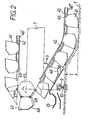
- Fig. 2 das Rückladegerät der Mischbettanlage in einer teilweise freigelegten, auszugsweisen Seitenansicht,
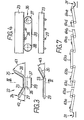
- Fig. 3 ein muldenförmiges Ausstapelband in einem schematisierten Querschnitt,
- Fig. 4 das Ausstapelband in einem auszugsweisen Längsschnitt längs der Linie IV-IV in Fig. 3,
- Fig. 5 ein flaches Ausstapelband in einem schematisierten Querschnitt,
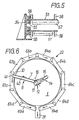
- Fig. 6 eine Ausstapelbandanlage mit mehreren Einzelbändern in einer Draufsicht und
- Fig. 7 die Ausstapelbandanlage nach Fig. 6 in einer abgewickelten Darstellung.
- 1 is a circular mixed bed system in a schematic cross section,
- 2 the reloading device of the mixed bed system in a partially exposed, excerpted side view,
- 3 shows a trough-shaped unloading belt in a schematic cross section,
- 4 shows the extracting belt in a partial longitudinal section along the line IV-IV in FIG. 3,
- 5 shows a flat stacking belt in a schematic cross section,
- 6 is a top view of a destacking belt system with several individual belts
- Fig. 7 shows the unwinding conveyor system according to Fig. 6 in a developed view.
Die Mischbettanlage nach Fig. 1 weist einen Rundlagerplatz bzw. ein Kreislagermischbett 1 auf, dessen Boden um das Maß T unter dem Mischbettrand liegt. In der Mitte des Kreislagermisch ettes 1 befindet sich eine Zentral- oder Rundsäule 2 mit zwei flanschartigen Tragringen 3 bzw. 4, die jeweils eine Kugeldrehverbindung 5 bzw. 6 aufnehmen.1 has a circular storage space or a circular storage mixed
An der einen Kugeldrehverbindung 5 ist das eine Ende der Brücke 7 eines Rückladegerätes 8 gelagert. Das andere Ende der Brücke 7 ist über Antriebsräder 9 auf um das Kreislagermischbett 1 angeordneten Schienen 10 fahrbar abgestützt.One end of the
Auf der anderen Kugeldrehverbindung 6 ist eine mit zwei Seitenwänden 11 versehene Stützkonstrukticn 12 drehbar gelagert. Zwischen den Seitenwänden 11 ist die Tragkonstruktion 13 eines Absetzers 14 mit einem Abwurfband 15 um eine waagerechte Achse 16 schwenkbar angeordnet.On the other
Auf der Stützkonstruktion 12 befindet sich eine weitere Kugeldrehverbindung 17, auf der sich die Tragkonstruktion 18 eines von außen in das Zentrum des Kreislagermischbettes 1 geführten Brückenbandes 19 abstützt. Unter der Umlenk-oder Abgabetrommel 20 des Brückenbandes befindet sich eine Aufgabeschurre 21, die das ankommende Schüttgut auf das Band 15 des Absetzers 14 weiterleitet.On the
Um das Kreislagermischbett 1 ist eine Ausstapelbandanordnung 22 angeordnet, die - in der Draufsicht gesehen - kreisrund ausgebildet ist. Die Bandanordnung 22 weist ein Ausstapelband 23 auf, dessen Länge am Außenumfang 24 entsprechend länger ausgebildet ist als die Länge an dessen Innenumfang 25. Das Obertrum des Ausstapelbandes 23 wird durch mittige Tragrollen 26 und durch seitliche Tragrollen 27, 28 gestützt, wobei die Tragrollen 28 am Innenumfang des Ausstapelbandes 23 unter einem Winkel a, geneigt sind, der größer ist als der Winkel a2 , um den die Tragrollen 27 am Außenumfang des Ausstapelbandes 23 geneigt sind. Das rücklaufende Untertrum des Ausstapelbandes 23 wird wiederum von Tragrollen 29, 30 gestützt, wobei die Tragrollen 30 am Innenumfang des Ausstapelbandes 23 unter einem Winkel a3 geneigt sind.A
Über einem von dem Kreislagermischbett 1 wegführenden Abzugsband 31 wird das Ausstapelband 23 jeweils um zwei konische Umlenktrommeln 32 und 33 in seine Kreisbahn zurück umgelenkt. Die Achsen 34 der Umlenktrommein 32, 33 sind im wesentlichen radial zur Säule 2 bzw. zum Zentrum des Kreislagermischbettes 1 ausgerichtet. Zwischen den beiden Umlenktrommein 32, 33 ist ein Zwischenraum, durch den das Schüttgut beim Verlassen des Ausstapelbandes 23 auf das Abzugsband 31 gelangen kann. Dabei ist eine Umlenktrommel 32 als Antriebstrommel und die andere Umlenktrommel 33 als Spanntrommel ausgebildet.The
Außer durch die eine Umlenktrommel (32) wird das Ausstapelband 23 noch durch weitere Antriebe 36 angetrieben, die gleichmäßig über dessen Umfang verteilt sind und die jeweils aus einer Antriebstrommel 37 und aus einer Spanntrommel 38 bestehen, die beide von einem umlaufenden Gurt oder Band 39 umspannt sind. Das Ausstapelband 23 liegt auf dem Gurt 39 auf und wird durch Reibungsschluß von diesem mitgenommen. Im Bereich der zusätzlichen Antriebe 36 sind die Tragrollen 26 unterhalb des Obertrums des Gurtes 39 angeordnet.In addition to the one deflection drum (32), the
Das Rückladegerät 8 weist eine mit Eimern 41 versehene, umlaufende Kette 42 auf, die um zwei Umlenkturasse 43, 44 umgelenkt und ober- und unterhalb der Brücke 7 über Rollen 45 in Führungsschienen 46', 46" geführt ist.The
Die Eimer 41 weisen ein im wesentlichen parallel zur Kette 42 verlaufendes Fuß- oder Unterblech 47 auf sowie eine dazu unter einem Winkel a4 geneigte Rückwand 48 und eine zwischen der Rückwand 48 und der Kette 42 befindliche rückwärtige Öffnung 49. Vor dem Umlenkturas 43 ist die Führungsschiene 46" unter einem Winkel a5 gegen die Horizontale geneigt, der kleiner oder gleich dem Winkel a4 ist so daß die Rückwand 48 in dem Bereich vor dem Umlenkturas 43 in etwa waagerecht ausgerichtet ist und dem in dem Eimer 41 befindlichen Schüttgut einen tragfähigen Halt gibt.The
Außerhalb des Mischbettes 1 ist im Bereich des schrägen Verlaufs der Führungsschienen 46" eine Schurre 50 mit der Brücke 7 verbunden. Im Bereich des Umlenkturas 43 fällt unten auf das Ausstapelband 23. Das zwischen den einzelnen Eimern 41 befindliche Schüttgut wird entlang der Schurre 50 geschoben und am Ende der Schurre 50 auf das Ausstapelband 23 übergeben.Outside the
Bei einem anderen Ausführungsbeispiel (vgl. Fig. 5) weist die Ausstapelbandanlage 22 ein im wesentlichen waagerechtes Ausstapelband 53 auf, das an seinem Aufenumfang 54 an der Ober-und an der Unterseite mit einer Vielzahl von Druckrollen 55 versehen ist, die sich gegen Schienen 56 abstützen, die um das Kreislagermischbett 1 angeordnet sind. Das Ausstapelband 53 ist lediglich auf waagerechten Trag- oder Stützrollen 57, 57' abgestützt und im übrigen, wie bei dem Ausführungsbeispiel gemäß Fig. 1 über dem Abzugsband 31 um konische Umlenktrommein 32, 33 umgelenkt und mit zusätzlichen Antrieben 36 versehen. Zur seitlichen Begrenzung des Schüttgutes weist das Ausstapelband 53 wellenförmig ausgebildete elastische Längswülste 58 auf, die ein Umlenken des Bandes 53 mit vollziehen.In another exemplary embodiment (cf. FIG. 5), the
Bei dem Ausführungsbeispiel gemäß Fig. 6 und 7 besteht die Ausstapelbandanordnung 22 aus zwei Gruppen von jeweils einer Vielzahl von Förderbändern 63a...63e bzw. 64a...64e, wobei die Gruppen jeweils an der dem Abzugsband 31 gegenüberliegenden Stelle beginnen. Die Abwurfstelle des jeweils letzten Bandes der beiden Gruppen 63e bzw. 64e befindet sich über dem Abzugsband 31. Je nach Stellung des Rückladegerätes wird das Schüttgut über die zum Abzugsband 31 führenden Bänder 63a...63e oder 64a...64e transportiert.In the exemplary embodiment according to FIGS. 6 and 7, the
Zur besseren Angleichung der Bandgruppen an eine Kreisform können die einzelnen Bänder 63a...63e bzw. 64a...64e jeweils auch bogenförmig ausgebildet sein.For better matching of the band groups to a circular shape, the
Claims (8)
Applications Claiming Priority (2)
| Application Number | Priority Date | Filing Date | Title |
|---|---|---|---|
| DE19843418433 DE3418433C2 (en) | 1984-05-18 | 1984-05-18 | Mixed bed system for bulk goods |
| DE3418433 | 1984-05-18 |
Publications (2)
| Publication Number | Publication Date |
|---|---|
| EP0162318A1 EP0162318A1 (en) | 1985-11-27 |
| EP0162318B1 true EP0162318B1 (en) | 1987-11-04 |
Family
ID=6236170
Family Applications (1)
| Application Number | Title | Priority Date | Filing Date |
|---|---|---|---|
| EP19850104949 Expired EP0162318B1 (en) | 1984-05-18 | 1985-04-24 | Blending bed plant for bulk material |
Country Status (2)
| Country | Link |
|---|---|
| EP (1) | EP0162318B1 (en) |
| DE (1) | DE3418433C2 (en) |
Cited By (1)
| Publication number | Priority date | Publication date | Assignee | Title |
|---|---|---|---|---|
| CN102046499B (en) * | 2008-06-11 | 2013-11-20 | 安德里兹公司 | An apparatus for storing rolling material in a pile and reclaiming from the pile |
Family Cites Families (5)
| Publication number | Priority date | Publication date | Assignee | Title |
|---|---|---|---|---|
| DE367590C (en) * | 1921-09-24 | 1923-01-23 | Jacob B Jacobsen | Continuous conveyor consisting of two or more strings |
| DE2544270A1 (en) * | 1975-10-03 | 1977-04-14 | Pohlig Heckel Bleichert | CIRCULAR STORAGE UNIT FOR MOVING AND UNSTORING OF SCHUETTGUT |
| DE7707677U1 (en) * | 1977-03-12 | 1977-06-23 | Steiff Foerdertechnik, 7928 Giengen | CONVEYOR DEVICE |
| DE7904817U1 (en) * | 1979-02-21 | 1979-05-23 | Gustav Schade Maschinenfabrik Gmbh & Co, 4600 Dortmund | EQUIPMENT FOR CLEARING ROUND STACKS |
| FR2529176B1 (en) * | 1982-06-25 | 1986-10-03 | Reveyron Ets | CURVED BELT CONVEYOR |
-
1984
- 1984-05-18 DE DE19843418433 patent/DE3418433C2/en not_active Expired
-
1985
- 1985-04-24 EP EP19850104949 patent/EP0162318B1/en not_active Expired
Cited By (1)
| Publication number | Priority date | Publication date | Assignee | Title |
|---|---|---|---|---|
| CN102046499B (en) * | 2008-06-11 | 2013-11-20 | 安德里兹公司 | An apparatus for storing rolling material in a pile and reclaiming from the pile |
Also Published As
| Publication number | Publication date |
|---|---|
| EP0162318A1 (en) | 1985-11-27 |
| DE3418433A1 (en) | 1985-11-21 |
| DE3418433C2 (en) | 1986-06-26 |
Similar Documents
| Publication | Publication Date | Title |
|---|---|---|
| DE112016000753B4 (en) | Environmentally friendly circular storage with a main roof and a secondary roof | |
| DE3038351A1 (en) | METHOD AND DEVICE FOR RECOVERY OF MATERIALS | |
| DE2122518B2 (en) | Device for storing bulk material in layers parallel to the angle of slope | |
| EP0162318B1 (en) | Blending bed plant for bulk material | |
| DE3233742A1 (en) | Silo for loose material | |
| DE2815480A1 (en) | UNLOADING DEVICE FOR SHIPS, BUNKERS, STORAGE AREAS OR DGL. | |
| DE1291244B (en) | Ship's own conveyor system | |
| EP0254953A1 (en) | Silo for bulk material | |
| DE3515261A1 (en) | Crusher device | |
| DE2114640A1 (en) | Device for cleaning potato pieces | |
| DE649975C (en) | Device for transferring material to be conveyed between two conveyor belts or the like connected in series. | |
| DE2837881A1 (en) | DEVICE FOR READING LOTS OF PRODUCTS | |
| EP0010648B1 (en) | Method and apparatus for precision manufacturing of balls | |
| WO1998055410A1 (en) | Sludge silo | |
| DE3130775C2 (en) | Polygon belt transfer | |
| DE2808338A1 (en) | Dockside bulk material rotary hopper - has wall formed by endless belt deflected by rollers at discharge chute | |
| DE8124756U1 (en) | DEVICE FOR THE TRANSFER OF SCHUETTGUT | |
| DE954044C (en) | Charging device | |
| DE3234005A1 (en) | Funnel-shaped transfer device for loading machines | |
| DE2301598A1 (en) | DEVICE FOR REMOVAL OF HOPES | |
| DD202124A5 (en) | METHOD AND MACHINERY FOR THE TRANSPORT OF SHOE LOADERS | |
| AT215896B (en) | Mobile dismantling and charger | |
| CH378784A (en) | Concrete handling system for construction sites | |
| DE8528622U1 (en) | Device for processing soil and the like. | |
| DE1172606B (en) | High conveyor |
Legal Events
| Date | Code | Title | Description |
|---|---|---|---|
| PUAI | Public reference made under article 153(3) epc to a published international application that has entered the european phase |
Free format text: ORIGINAL CODE: 0009012 |
|
| AK | Designated contracting states |
Designated state(s): FR GB IT NL |
|
| 17P | Request for examination filed |
Effective date: 19860425 |
|
| 17Q | First examination report despatched |
Effective date: 19870127 |
|
| GRAA | (expected) grant |
Free format text: ORIGINAL CODE: 0009210 |
|
| AK | Designated contracting states |
Kind code of ref document: B1 Designated state(s): FR GB IT NL |
|
| ET | Fr: translation filed | ||
| ITF | It: translation for a ep patent filed |
Owner name: STUDIO JAUMANN |
|
| PG25 | Lapsed in a contracting state [announced via postgrant information from national office to epo] |
Ref country code: NL Effective date: 19881101 |
|
| NLV4 | Nl: lapsed or anulled due to non-payment of the annual fee | ||
| PG25 | Lapsed in a contracting state [announced via postgrant information from national office to epo] |
Ref country code: FR Free format text: LAPSE BECAUSE OF NON-PAYMENT OF DUE FEES Effective date: 19881229 |
|
| REG | Reference to a national code |
Ref country code: FR Ref legal event code: ST |
|
| PG25 | Lapsed in a contracting state [announced via postgrant information from national office to epo] |
Ref country code: GB Effective date: 19890424 |
|
| GBPC | Gb: european patent ceased through non-payment of renewal fee | ||
| PLBE | No opposition filed within time limit |
Free format text: ORIGINAL CODE: 0009261 |
|
| STAA | Information on the status of an ep patent application or granted ep patent |
Free format text: STATUS: NO OPPOSITION FILED WITHIN TIME LIMIT |
|
| 26N | No opposition filed |