EP0162234A2 - Speicheranordnung - Google Patents
Speicheranordnung Download PDFInfo
- Publication number
- EP0162234A2 EP0162234A2 EP85103712A EP85103712A EP0162234A2 EP 0162234 A2 EP0162234 A2 EP 0162234A2 EP 85103712 A EP85103712 A EP 85103712A EP 85103712 A EP85103712 A EP 85103712A EP 0162234 A2 EP0162234 A2 EP 0162234A2
- Authority
- EP
- European Patent Office
- Prior art keywords
- decoder
- clock
- cas
- address
- shift register
- Prior art date
- Legal status (The legal status is an assumption and is not a legal conclusion. Google has not performed a legal analysis and makes no representation as to the accuracy of the status listed.)
- Withdrawn
Links
Images


Classifications
-
- G—PHYSICS
- G11—INFORMATION STORAGE
- G11C—STATIC STORES
- G11C7/00—Arrangements for writing information into, or reading information out from, a digital store
- G11C7/10—Input/output [I/O] data interface arrangements, e.g. I/O data control circuits, I/O data buffers
- G11C7/1078—Data input circuits, e.g. write amplifiers, data input buffers, data input registers, data input level conversion circuits
- G11C7/1093—Input synchronization
-
- G—PHYSICS
- G11—INFORMATION STORAGE
- G11C—STATIC STORES
- G11C7/00—Arrangements for writing information into, or reading information out from, a digital store
- G11C7/10—Input/output [I/O] data interface arrangements, e.g. I/O data control circuits, I/O data buffers
- G11C7/1006—Data managing, e.g. manipulating data before writing or reading out, data bus switches or control circuits therefor
-
- G—PHYSICS
- G11—INFORMATION STORAGE
- G11C—STATIC STORES
- G11C7/00—Arrangements for writing information into, or reading information out from, a digital store
- G11C7/10—Input/output [I/O] data interface arrangements, e.g. I/O data control circuits, I/O data buffers
- G11C7/1015—Read-write modes for single port memories, i.e. having either a random port or a serial port
- G11C7/1018—Serial bit line access mode, e.g. using bit line address shift registers, bit line address counters, bit line burst counters
-
- G—PHYSICS
- G11—INFORMATION STORAGE
- G11C—STATIC STORES
- G11C7/00—Arrangements for writing information into, or reading information out from, a digital store
- G11C7/10—Input/output [I/O] data interface arrangements, e.g. I/O data control circuits, I/O data buffers
- G11C7/1015—Read-write modes for single port memories, i.e. having either a random port or a serial port
- G11C7/103—Read-write modes for single port memories, i.e. having either a random port or a serial port using serially addressed read-write data registers
- G11C7/1033—Read-write modes for single port memories, i.e. having either a random port or a serial port using serially addressed read-write data registers using data registers of which only one stage is addressed for sequentially outputting data from a predetermined number of stages, e.g. nibble read-write mode
-
- G—PHYSICS
- G11—INFORMATION STORAGE
- G11C—STATIC STORES
- G11C7/00—Arrangements for writing information into, or reading information out from, a digital store
- G11C7/10—Input/output [I/O] data interface arrangements, e.g. I/O data control circuits, I/O data buffers
- G11C7/1051—Data output circuits, e.g. read-out amplifiers, data output buffers, data output registers, data output level conversion circuits
- G11C7/106—Data output latches
-
- G—PHYSICS
- G11—INFORMATION STORAGE
- G11C—STATIC STORES
- G11C7/00—Arrangements for writing information into, or reading information out from, a digital store
- G11C7/10—Input/output [I/O] data interface arrangements, e.g. I/O data control circuits, I/O data buffers
- G11C7/1078—Data input circuits, e.g. write amplifiers, data input buffers, data input registers, data input level conversion circuits
- G11C7/1087—Data input latches
-
- G—PHYSICS
- G11—INFORMATION STORAGE
- G11C—STATIC STORES
- G11C7/00—Arrangements for writing information into, or reading information out from, a digital store
- G11C7/22—Read-write [R-W] timing or clocking circuits; Read-write [R-W] control signal generators or management
-
- G—PHYSICS
- G11—INFORMATION STORAGE
- G11C—STATIC STORES
- G11C8/00—Arrangements for selecting an address in a digital store
- G11C8/04—Arrangements for selecting an address in a digital store using a sequential addressing device, e.g. shift register, counter
-
- G—PHYSICS
- G11—INFORMATION STORAGE
- G11C—STATIC STORES
- G11C8/00—Arrangements for selecting an address in a digital store
- G11C8/10—Decoders
-
- G—PHYSICS
- G11—INFORMATION STORAGE
- G11C—STATIC STORES
- G11C8/00—Arrangements for selecting an address in a digital store
- G11C8/18—Address timing or clocking circuits; Address control signal generation or management, e.g. for row address strobe [RAS] or column address strobe [CAS] signals
-
- G—PHYSICS
- G11—INFORMATION STORAGE
- G11C—STATIC STORES
- G11C2207/00—Indexing scheme relating to arrangements for writing information into, or reading information out from, a digital store
- G11C2207/10—Aspects relating to interfaces of memory device to external buses
- G11C2207/107—Serial-parallel conversion of data or prefetch
Definitions
- the present invention relates to a memory device, and more particularly, to a semiconductor memory device fabricated on a semiconductor substrate.
- IGFET insulated gate field effect transistors
- memory capacity has been steadily increasing at a rate of twice per year owing to the rapid progress of the integration technique, especially fine patterning technique, in the recent years.
- Memories having storage capacities of 1K bits, 4K bits, 16K bits and 64K bits have been successively made commercially available.
- 256 K bit memories have been produced on the laboratory scale, and realization of 1 M bit memories is also expected in the near future.
- a number of pins in a package has been decreased and a mount density of memory devices has been increased by multiple-addressing technique detailed in United States Patent No.
- a buffer memory for comensating the difference in operation speeds therebetween and enhancing a processing s[eed pf a CPU.
- Mutual data exchanges are generally affected on information block units having a fixed length of several tens bytes.
- contrivance in a system construction called "interleave" has been made, in which in order to enhance a throughout of a memory, a memory card group forming a main memory is divided into a plurality of banks, and consecutive successive addresses are allotted to these banks.
- parallel processing is effected, and also improvements in operation speed are achieved by shortening of an average memory cycle period and by page mode operations.
- a memory device of the type defined in the preamble part of claim 1 has been known from US-A-39 30 239.
- a shift signal for controlling the shift operations of the shift register for serially selecting the columns is supplied from the outside of the memory by way of a terminal; which must be provided in addition to the terminals receiving row and column strobe signals.
- the shift register controls the transfer of a read-out signal through activation of a.selected switching element, a predetermined period of time will elapse from the operation of the shift register to the time that a read-out signal appears at an output terminal. This imposes a limitation on the operation speed in the consecutive selection of columns by the shift register.
- a first portion of the column address signals selects a limited number of the column lines by means of an additional column decoder and a second portion of the column address signals determines one of the selected comlumn lines by means of the first column decoder, whereby the dater of the selected column lines are serially outputed, starting from that of the determined one, by the shift register.
- the present invention is particular applicable to a memory device of the type employing a plurality of pairs I/O buses.
- Information appearing at part of the columns is electrically transmitted to a plurality of first bus lines responsive to a part of the column address information, and then the first bus lines are consecutively selected one by one by means of a shift register to be electrically coupled to a second bus line.
- the essence of the present invention resides in that a shift register is assembled in a column decorder in a two-phase clock multi-address type RAM and it is made possible to access to memory cells allotted with consecutive column addresses at a high speed by effectively utilizing the shift function of this shift register. Since in the process of access in a practically used system the probability of accessing to consecutive addresses is very high and the occurence of such accesses is also extremely high, owing to the above-described memory structure the memory device according to the present invention can achieve greatly remarkable effects and advantages as compared to the heretofore known RAM.
- any arbitrary address information is taken in, and as soon as a memory cell is accessed, Y-address information is taken in a shift register. Thereafter, when the operation transfers to a page mode relying upon only the CAS clock, a shift clock is generated as synchronized to the CAS clock only, and thereby shift of the Y-address taken in during the RAS/CAS cycles is commenced.
- the shift of the address information controlled by the shift register is effected for each bit in response to a series of shift clock pulses generated in the respective cycles of the CAS clock.
- the present invention can bring about remarkable effects and advantages that quite novel functions which were not present in the page mode in the prior art are produced and high-speed access is made possible. Moreover, even in the case of not employing a page mode, the functions of the heretofore known RAM are not deteriorated at all.
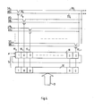
- a basic structure of a memory device according to the present invention will be explained with reference to Fig. 1, in which one example of a RAM of (M rows X N columns) words X I bit is illustrated.
- the present invention can be practiced in any type of RAM's employing any multi-address system, whether the RAM may be static type or dynamic type, and in the latter case whether the RAM may employ a single-phase clock multi-address system or a two-phase clock multi-address system. In the following description, it is assumed that the RAM employs a tvo -phase clock multi-address system.
- memory cells are arrayed in a matrix 11 of M rows X N columns, and the row and column of the matrix 11 are selected by an X-decoder 12 and a Y-decoder 14, respectively.
- To the X- and Y-decoders 12 and 14 are fed address data from X- and Y-address buffers (not shown).
- X- and Y-address buffers not shown.
- the Y-decoder 14 has the function of selecting one of the N memory cells selected according to the X-address and carrying out switching to an input/ output circuit. Thus, externally the memory device looks like a RAM of (M rows X N columns) words X 1 bit. Furthermore, the Y-decoder 14 has a shift register assembled therein. This shift register has the function of taking in and temporarily holding the Y-address information determined in the first RAS/CAS cycle, and carrying out transfer bit by bit in response to a transfer clock generated in synchronism with the CAS clock only when the memory device is put in a page mode controlled only by the CAS clock.
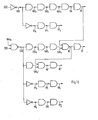
- FIG. 2 Another basic construction of the memory device according to the present invention is illustrated in Fig. 2.
- the address signals fed from the Y-address buffer are divided into two parts, and one part of the address signals is fed to a Y-decoder 14' to select L-bit data among the N-bit data for the memory cells selected by the X-address and to transfer an input/output switch 13 for transmitting the respective L-bit data to L pairs of I/O buses.
- the other past of the address signals is fed to another Y-decoder 15 provided with a shift register function to select one arbitrary pair among the L pairs of I/O buses.
- the shift register is operated by shift clock pulses which are generated each time the CAS clock pulse is input thereto to successively select one bus pair among the L pairs of I/O buses which were selected according to the Y-address information that was decided in the first RAS/CAS cycle and taken into the Y-decoder 14'.
- access can be started from any address among the L-bi addresses, and any bits of consecutive addresses can be accessed so long as the number of bits is smaller than L.
- L' bits which is larger than L bits, provided that the condition of L ⁇ N is fulfilled.
- the modified circuit construction illustrated in Fig. 2 is not different at all in the basic operations from the first preferred embodiment described previously with reference to Fig. 1.
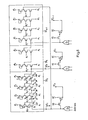
- Fig. 3 shows the first preferred embodiment in Fig. 1 in greater detail, in which a Y-decoder 20 associated with a shift register YSR, single-transistor type memory cells MC and sense amplifiers SA.
- a simple register operation will be described in the following.
- the X-address signal is latched, and when the X-address buffer operates, address binary- codes are produced.
- These signals are fed to the X-decoder, in which one decoder output from one decoder unit is selected among the M decoder outputs.
- one word line is selected, hence memory cells connected to the selected word line are energized, and subsequently the memory cell informations are transmitted to sense amplifiers SA to be amplified. Thereafter, at the trailing edge of the CAS clock a Y-address signal 21 is latched, and thereafter a series of operations occur sequentially in the Y-address buffer (not shown) and the Y-address decoder 20.
- one bit selected by the Y-decoder 20 among the N-bit memory cell information selected by the X-decoder is transferred to an input/output bus I/O via transfer gates TF l and TF 2 .
- Fig. 4 shows the construction of the Y-decoder 15 associated with a shift register SR included in the arrangement shown in Fig. 2.
- This Y-decoder 15 selects one of L pairs of input/output buses I/O 0 , I/O 0 I/O L-I , I/O L-1 to connect it to a pair of data bus D I/O, DI/O.
- the function of the shift register SR itself is not different at all from that of the shift register SR shown in Fig. 3, and basically the operations of these shift registers are exactly the same.
- Reference symbols TF A and TF B designate transfer gate transistors controlled by a decode output YE 0 .
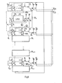
- Fig. 5 shows a circuit construction of a decoder associated with n-bit shift register (SR O , SR n-1 ) to be employed according to the present invention.
- a decoder for a MOS dynamic RAM employs a NOR logic structure.
- the shift registers those relying upon a two-phase clock system or a four-phase clock system are generally used, and the shift register can be constructed by employing either one of the above clock systems.
- the register of the four-phase clock system has such advantages that various clocks can be generated and also any clock suitable for the use can be generated because a clock generator is provided within the device and that a power consumption is generally small. The following description will be made in connection to the case where the register of the four-phase clock system is employed.
- a four-phase drive register operates generally to repeat the cycle consisting of take-in, evaluation, hold and transfer of data. Accordingly, in the case of incorporating the shift register in the decoder circuit, it is only necessary to drive the register by providing a control circuit which takes n data into the register after the decision by the decoder and which generates a group of four-phase clocks ⁇ 4 after commencement of the next memory cycle and before the next decision by the decoder. More particularly, the decoder associated with the shift register provided according to the present invention operates in the following manner. When the address decoder unit Do is selected in the first RAS/CAS cycle, the NOR output node of the decoder unit Do becomes "I", and all the remaining decoder units D l -- D n-1 become "0".
- a set of shift register drive clocks d 1 - ⁇ 4 are generated in synchronism with the energization of CAS, so that the shift register starts its shift operation.
- selective level latched by the stage SR O is transferred to the subsequent stage SR I of the shift register.
- the column select signal YE 1 is energized.
- the stage SR 0 is changed to the non-selective level by the data shift from the stage SR n-1 , and the other stages SR 2 --SR n-1 remain non-selective level.
- the mentioned shift operation of the shift register is continued per each of the energization of CAS.
- the selective level is shift from the stage SR 0 towards the stage SR n- one bit by one bit, and the column shift signal is energized from YE 0 to YE n-1 , step by step.
- the clock in charge of "transfer” among the shift register drive clock group ⁇ 1 -- ⁇ 4 " may be generated at the same time with the start of the CAS clock, then a remarkable effect can be expected in shortening the heretofore known page mode access time because the time required for driving the address buffer in the prior art can be omitted.
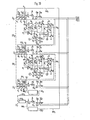
- Fig. 6 shows one practical example of a decoder in which a four-phase drive shift register is assembled, and the operation of the decoder will be explained hereunder with reference to the shift register drive clock waveforms illustrated in Fig. 7. It is assumed now that in the first RAS/CAS cycle, a Y-address decoder unit D 0 has been selected according to the Y-address information. Accordingly, the NOR nodes of the respective decoder units take "1'' level for the decoder unit D 0 and "0" level for the decoder units D 1 --D n-1 , and the information of these levels serve as input information to the shift register.
- transistors Q 3 included in the respective shift register stages SR 0 --SR n-1 are turned ON, so that a transistor Q 1 in the register stage SR 0 is turned ON and charges a capacitor G 2 .
- the transistors Q l in the other register stages SR 1 --SR n-1 are turned OFF.
- a transistor Q 3 in the register stage SR 0 is turned ON and charges a capacitor C 3 .
- a transistor Q6 is turned ON and charges a capacitor C 5 .
- a colck ⁇ 3 comes in, since the transistor Q 4 is held OFF because of the ground potential at its gate, the charge on the capacitor C 5 flows into the capacitor C 4 through the transistor Q 5 , so that the voltage across the capacitor C 5 is maintained at a value determined by the capacitance ratio between the capacitors C 4 and C 5;
- the capacitance ratio between the capacitors C 4 and C 5 is set at such value that the transistor Q 7 can be well turned ON. Then the transistors Q 7 and Q 9 are turned ON, so that the capacitors C 6 and C 7 can be charged.
- a transistor Q 8 When a clock ⁇ 4 comes in, a transistor Q 8 is turned ON, and the transistor Q 7 is held ON because its gate is maintained at a high potential by the charge stored on the capacitor C 5 , so that the charge on the capacitors C 6 and C 7 is discharged through the transistors Q 7 and Q 8 , and the potential on the capacitor C 7 is brought to the ground potential.
- the NOR node of the decoder unit D 1 may be precharged before the clock ⁇ 4 comes in.
- the outputs of the n decoder units D 0 --D n-1 have been taken in as input information of the n shift register stages SR 0 --SR n-1 and have been transferred to just before the register stages corresponding to the decoder units at the next addresses.
- the operation of the address buffer is inhibited. Only the information taken in and held in the preceding cycle is transferred to the next shift register stages as controlled by the transfer clock ⁇ 1 , and thereby the state of the decoder is determined.
- Fig. 8 is illustrated one example of a decoder having a shift register function according to a two-phase clock system, and a practical circuit construction of the decoder is shown in Fig. 9.
- a decoder unit D 0 has a NOR gate construction in which address binary signals are input in a selected combination.
- a latch circuit LA 0 is activated by a clock ⁇ 1 and holds a decoder output YE 0 .
- the decoder output YEo held by the latch circuit LA 0 is transmitted to a gate of a pull-up transistor 83 in the next shift register stage SR 1 via a transistor Q21 and is also applied to a reset transistor Q 82 of the latch circuit LA 0 to reset the latch circuit LA 0 .
- the output of the shift register (SR 0 -SR L-1 ) is shifted in synchronism with the clocks ⁇ 1 - ⁇ 2 one stage by one stage for each period of the clocks.
- Transistors O A and Q B for producing transmission signals on the basis of the decoded information YE i stored at the latch circuit output node upon transfer of the decoded information to the next decoder stages in responce to a second clock 6 T after the decoded information has been taken into the latch circuits in response to a first clock ⁇ L are provided as two separate independent transistors, one (Q A ) resetting the selected decoder unit output node to the ground potential immediately after commencement of the transfer, the other (Q B ) selectively charging the next stage decoder unit output node.
- a transistor Q D for resetting the raised potential at the node R 0 to the ground potential in response to the clock ⁇ L immediately after the transfer of the decoded information in response to the clock ⁇ T .
- clocks taking charge of principal functions such as latch transfer, etc. have their operation amplitudes set at the power supply level.
- the transfer operation in response to the clock ⁇ T according to the present invention is effected during the reset period of the CAS in the consecutive access mode, if the reset period of the CAS becomes extremely short, the selective charging will become so insufficient that the potential at the output code of the next stage decoder unit cannot be raised sufficiently. Therefore, there arises a risk that a non-selection condition of the decoder may be generated.
- a decoder for a RAM employs a NOR logic construction.
- each of decoder units D 0 , D 1 , .... D 7 is composed of three transistors Q 1 to Q 3 which are OR-connected for address binary codes and a load transistor Q 4 subjected to control by a clock PYD.
- address binary codes are generated by an address buffer, and before the address binary codes are transmitted to the address decoder, the clock PYD transfers from "1" level to "0" level, and thereby precharge is completed.
- a node YEO is raised via transistors Q 5 and Q 6 , transfer gate transistors Q 7 and Q 8 are controlled by the potential on the node YEO, and thereby the information on the selected I/O bus pair I/0 0 , I/0 0 is transmitted to the data bus pair D I/O, D I/O.
- the clock ⁇ L is synchronized with the clock adapted to control the transfer gate transistors for transmitting the memory cell information amplified by the sense amplifiers on the basis of an output of another decoder, then provision is made such that these clocks may rise almost at the same time as that the clock ⁇ L may not precede, and thus contrivance is made such that the increase of an access time during the RAS/CAS cycle may not be prevented.
- the same clock ⁇ 2 also takes charge of latching the Y-address information during the RAS/CAS cycle.
- a two-stage dynamic inverter connected at a predetermined parameter ratio which consists of transistors Q 9 to Q 12 forms a latch circuit with the aid of the drive by the clock ⁇ L , so that the decoded address information is stored at a node marked B.
- the basic operation of this latch circuit is as follows. It is now assumed that the decoder unit D 0 has been selected in the RAS/CAS cycle.
- the NOR output nodes of the respective decoder units are at logic "1" level for the decoder unit D 0 and at logic "0" level for all the decoder units D 1 --D 7 , and there logic levels serve as input information for the shift register.
- the transistor Q 10 In response to the information "1" fed from the selected decoder unit D 0 , the transistor Q 10 is turned ON, so that a node marked A is brought to "0" level as decided by a given parameter ratio between the transistors Q 9 and Q 10 , in response to this "0" level the transistor Q 12 is turned OFF, and the node B is charged up to the level of V DD --V T (V T being a threshold voltage of the MOS transistor) because the transistor Q 11 controlled by the clock ⁇ L is turned ON.
- the level of the clock ⁇ L is selected at the V DD level in order to raise the charge-up level of the node B as high as possible.
- this latch circuit can latch or renew the selection or unselection information of the decoder unit without affecting the decoder unit at all. More particularly, in the case where the decoder unit D 0 is selected in the first RAS/CAS cycle and subsequently another decoder unit is selected in the next RAS/CAS cycle, the potential change at the decoder information storing node B in the shift register stage SRO is as follows. At first, when the decoder unit Do has been selected, the subsequently produced latch clock ⁇ L starts a latch operation in response to the selection, and the node B is charged u p to the level of V DD -V T .
- the node NOR O becomes "0" level and turns the transistor Q 10 OFF, so that the node A is charged up to the level of V DD -V T by the clock ⁇ L . Thereafter, immediately the transistor Q 12 is turned ON, and hence it discharges the charge stored at the node B.
- a transistor Q' 10 is turned OFF and a transistor Q 12 ' is turned ON, so that the charge at the decoder information storing node is held discharged by the clock ⁇ L , and thus "0" level can be maintained.
- the latch and renewal operations of the decoded information would be carried out within the shift register, but thereafter if the operation is switched to a consecutive access mode, that is, to a page mode controlled only by the CAS clock, then the transfer clock ⁇ T . is generated immediately after the resetting of the CAS to commence the transfer operation during the reset period of the CAS.
- the decoder unit D 0 is selected and the other decoder units D 1 --D 7 are kept unselected in the RAS/CAS cycle just prior to the switching to a consecutive access mode, that is, a page mode, and thereafter the operation is switched to the consecutive access mode.
- the decoded information is latched by the clock ⁇ L in the RAS/CAS cycle, so that the node B in the shift register stage SRO is held at "1" level, while the nodes corresponding to the node B within all the other shift register stages including the node B within the shift register stage SRI are held at "0" level.
- the charged level and charging time of the charging of the boot-strap capacitor CB 0 through the transistor Q 17 are controlled respectively by a conductance ratio between transistors Q 19 and Q 20 and a delay circuit constructed by transistors Q 23 --Q 26 .
- the transistor Q 20 is turned OFF and opens a node C to which one end of the boot-strap capacitor CB 0 is connected so that the potential at the node can rise, and hence a node PSY 0 commences to rise quickly exceeding the power supply level owing to the well-known boot-strap effect, turns a transistor Q 27 ON and thereby charges a NOR output node NOR 1 of the decoder unit D 1 which is adjacent to the decoder unit D 0 selected during the RAS/CAS cycle.
- the transistor Q 22 acts the role of switching the potential at the node B from "I" level to "0" level to turn OFF the transistor Q 17 , for the purpose of preventing reverse flow of charge from the node PSY O to the clock ⁇ T caused by the turning ON of the transistor Q 17 when the node PSY 0 is raised to a potential higher than the power supply level by the generation of the boot-strap effect. Since the node C rises up to the power supply level in accordance with the potential rise at the node PSY 0 , the transistor Q 21 further promote the potential change at the node B which is caused by the turning ON of the transistor Q 22 .
- the transistor Q 18 causes the stored charge on the boot-strap capacitor CB 0 to be discharged by means of the latch clock ⁇ L which is generated during an activation period of a consecutive access mode to which the operation is switched after transfer of decoded information during the reset period of the CAS, and thereby switches the potential at the node PSY 0 to "0" level.
- the shift register stages SRI--SR7 connected to the unselected decoder units D 1 --D 7 all the decoded information storing nodes including, for example, the node in the shift register stage SRI, are maintained at "0" level.
- transistors Q 14 ' and Q 17 ' are held OFF, charging of the boot-strap capacitor caused by application of a transfer clock ⁇ T is not effected, and potential rise at the node PSY cannot be observed.
- a transfer clock ⁇ T the decision of either selection or unselection of decoder units in a consecutive access mode is effected according to a quite novel system not found in the prior art, that is, it is effected by selective charging of decoder NOR output nodes by means of a transfer clock ⁇ T .
- the translator Q 14 acts the role that upon transfer of decoded information to the next decoder stage controlled by the clock ⁇ T , it raises the potential at a node F, and in response thereto it turns ON the transistor Q 15 to switch the selection information of the preceding decoder stage of "1" level to "0" level and to turn the selected decoder unit to an unselected state.
- the transistor Q16 restores the potential at the node F which has been switched to "1" level at this moment, to "0" level during the activation period in preparation for the next cycle.
- the transistor Q 13 has the function that upon unselectionof a decoder unit, it feeds back the output of the dynamic inverter consisting of the transistors Q 9 and Q 10 which operate in response to "0" level at the decoder NOR output node, receives the logic "1" level at the node A which has risen in potential, and thereby fixedly holds the decoder NOR output node at the ground potential.
- the flip-flop formed by the transistor Q 10 and the transistor Q 13 by feeding back the potential at the output node of the inverter, stably maintains the NOR output node of the unselected decoder at the ground potential owing to the fast that the node A is charged in each cycle by the clock ⁇ L and thus held at the logic "1" level, and thereby serves to prevent occurrence of multiple selection.
- the dimension of one transistor Q 13 forming the flip-flop is designed as small as possible.
- the output node NOR O rises in accordance with the rise of the node PSY 7 and quickly turns ON the transistor Q 10 , hence the node A is restored to the ground potential. Therefore, the transfer operation in response to the clock ⁇ T , can be achieved smoothly.
- the charging clock PY D for the respective decoder units is preset so as to exceed the power supply level, because the selective charging clocks PSY i upon consecutive access cycles rise higher than the power supply level and thus charge up the selected decoder unit to the power supply level.
- the above-mentioned is a series of operations in the circuit illustrated in Fig. 10.
- the decoder associated with a shift register according to the present invention can bring out an epock-making property of a memory device that a consecutive access cycle time is as small as 70 ms, owing to the facts:
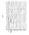
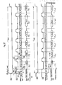
- Timing generator employed in the present invention is illustrated in Fig. 12, and timing waveforms appearing in this timing generator are illustrated in Fig. 13.
- the operation of the timing generator will be explained in the following with reference to these figures. In the illustrated example, description will be made in connection to the four-phase driven shift register shown in Fig. 6.
- a timing signal RAS converted to an internal MOS level rises.
- XP 1 and XP 2 are reset, and RAS 0 , RAS 1 and RAS 2 rise successively, so that a row address buffer responds to address information.
- Address binary codes are transmitted from the address buffer to a row decoder, and when a selection/unselection operation of the row decoder has been completed, a timing signal RA rises and a selected word line is driven to rise. Thereafter, in response to the RA, a timing signal SE rises, and when sense amplifiers are activated, the contents in N memory cells connected to the selected word line are amplified and refreshed. Then, the circuit operation in response to activation of the RAS has been finished.
- a first stage inverter to which the CAS is input is designed so as to operate normally in response to an activation signal of the RAS, for example, in response to a timing signal RAS O in order to assure the GATED CAS operation.
- activation of the CAS is effected only when the RAS 0 rises and also the CAS switches from “1" level to "0" level. Thereby, the CAS converted to the internal MOS level can rise.
- precharge timings YP 0 , YP 1 and YP 2 are reset, and also CAS 0 , CAS 1 and CAS 2 rise successively, so that a column address buffer responds to the address information.
- a timing RE rises, so that a digit line of a selected column is connected to a data input/output bus.
- a timing DE rises, so that an output amplifier is activated, and memory cell information appearing on the data input/output bus is amplified and transmitted via an output buffer to an output terminal. Then the activation operation controlled by the CAS has been finished.
- the CAS O , CAS 1 and CAS Z rise successively, and the column address buffer responds to the address information.
- the RE rises.
- a timing CAS O ' rises simultaneously with the CAS 0 , and in response thereto, a shift register drive clock ⁇ 4 is reset and another clock ⁇ 1 rises.
- the clock 6 4 is a data latch clock for the last stage of the shift register, and also it carries out precharge. Although data latched in the preceding stage is transferred in response to rise of the transfer clock ⁇ 1 and thereby the data would appear at the NOR outpul node of the decoder, since the clock YP 0 is preset so that precharge of the decoder may not be finished in the first RAS/CAS cycle, even if the transferred data should be "0", it would be cancelled and thus mulfunction would not occur.
- the RE' which commences to rise in response to the CAS 0 ' really commences to rise in response to rise of the RE which is preset to rise only in response to the fact that in the first RAS/CAS cycle, after the decision in the column address decoder and also after activation of the RAS, amplification by the sense amplifiers has been well achieved.
- the RE' preset so as to start rising after the selection/ unselection operations in the column decoder controlled by the shift register have been completed is also controlled by the RE analogously to that the CAS clock upon the RAS/CAS cycle is controlled by the RAS clock so as to prevent self-running of the CAS.
- the timing of the RE' which serves to connect a digit line to a data input/output bus in response to the CAS O ' which was separated from the CAS 0 for the purpose of generating a group of shift register drive clocks can be controlled so as not to be advanced.
- the transfer clock 6 1 is reset in response thereto, and the transfer is terminated.
- the clock ⁇ 1 the clock ⁇ 2 rises, the RE has already terminated its rising.
- the clock ⁇ 2 is preset so that it may maintain "1" level until the reset time of the CAS and may be reset in synchronism with the resetting of the CAS.
- the CAS 0 , CAS 1 , CAS 2 and RE maintain . "1" level until they are reset by the RAS.
- a shift register drive clock ⁇ 3 rises and acts to hold the information taken in internally.
- a one-shot operation is effected in such manner, that it may be reset after an appropriate time has elapsed, and subsequently, a clock ⁇ 4 rises to hold the information within the register.
- the clock 6 4 is reset to well hold the information within the register, and only the rise of the transfer clock ⁇ 1 is waited for. Again the CAS which was converted into the internal MOS level rises, and in response thereto the CAS 0 ' begins to rise. In accordance with the rise of the CAS 0 ', the clock ⁇ 1 also rises, so that the information in the column decoder unit which was taken in in the first RAS/CAS cycle and latched is transferred.
- the column decoder unit having the address next to the column decoder unit selected in the RAS/CAS cycle is selected.
- the CAS 0 , CAS 1 , CAS 7 and RE are activated in synchronism with the RAS, decision of selection/unselection of column decoder units in a page mode cycle, is effected in response to the clock 6 1 only. Therefore, among the time required before decision of the column decoder units in the heretofore known page mode cycle, the time required for operation of the column address buffer, at least the operation time of the CAS 1 and CAS 2 clock generators can be omitted, and therefore, the present invention brings about a remarkable effect in the shortening of the access time.
- the RE' rises in response to the selection and connects the selected digit line to the data input/output bus.
- the clock ⁇ 1 is reset, resulting in termination of the transfer, the clock ⁇ 2 rises, and so, the states of the respective decoder units are taken is as logic information.
- the clock 6 2 is preset in such manner that it may maintain "1" level until it is reset by the CAS clock.
- the DE rises, so that the memory cell information appearing on the data input/output bus is amplified and transmitted via an output buffer to an output terminal.
- clocks SE 0 , SE1, SE2 and SE3 rise successively, and when sense amplifiers are activated, the information in the N memory cells connected to the selected word line is amplified and refreshed. Then, the circuit operation in response to activation of the RAS has been finished.
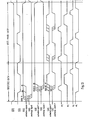
- the first buffer stage to which the CAS is input is normally designed so as to operate in response to an activation clock (for instance, the RA) of the RAS in order to assure a gated CAS operation, and thereby it is prevented that the CAS by itself starts the buffer stage. Accordingly, only when the RA rises to "1" level and the CAS switches from “1" level to “0” level, activation of the CAS may be effected. Thereby the CAS converted into the internal MOS level rises. In response to the CAS, clocks CASO and CAS' rise in potential.
- an activation clock for instance, the RA
- precharge clocks PYO, PY1, PY2 and PIO are reset, at the same time a clock CAS 1 rises, and a column address buffer responds to address information.
- a clock CAS 1 rises
- a column address buffer responds to address information.
- address binary codes are transmitted from the address buffer to a column decoder and selection/uncelection operations in the column decoder have been completed, the RE rises.
- the rise of the RE is subjected to control by a RAS series activation clock, for instance, the clock SE3.
- a clock OGEO is generated.
- This clock OGEO functions as a selective drive clock ( ⁇ 1 , ⁇ 2 ) for the input/output bus pairs.
- a column decoder for connecting a digit line to an input/output bus and a decoder to be used solely in a consecutive access mode for selecting a plurality of pairs of input/output bases are almost simultaneously operated, and in this way contrivance is made such that increase of an access time in a RAS/CAS cycle may not be resulted.
- precharge clock OP 0 , OP and PSR are reset and a clock OE is generated to activate an output buffer for transmitting memory cell information to a data output terminal.
- the column address information decided in the RAS/CAS cycle since the column address information decided in the RAS/CAS cycle has been taken in the shift register by the latch clock OGE, the column address information is transferred to the column decoder unit corresponding to the next address by the transfer clock PSR (corresponding to ⁇ 2 , ⁇ T in the previous description) generated during the reset period of the CAS.
- the transfer clock PSR (corresponding to ⁇ 2 , ⁇ T in the previous description) generated during the reset period of the CAS.
- the first buffer stage adapted to generate the CAS is designed to be subjected to the control by the RE, after the RE has risen in the RAS/CAS cycle, the control by the CAS is inhibited, so that even after the operation has switched to the consecutive access cycle controlled only by the CAS, the CAS is not reset but is maintained in an activated state.
- the I/O bus pair drive clock CSEO rises in response to the OGE, and thus select an input/output bus pair.
- the OE rises to amplify the information fed from the selected input/output bus pair by the output buffer amplifier and transmit the amplified information to the output buffer.
- the OPO, OP and PSR rise, and hence, precharge of the output buffer amplifier by the OP and transfer operation of the decoded information by the PSR are commenced.
- a novel memory device which is characterized in that after completion of necessary operations in the so-called RAS/CAS cycle in which the RAS and the CAS are successively activated, consecutive column addresses are internally produced on the basis of the previously introduced column address information without intervention of the operation of the column address buffer and decoder.
- the memory device can have a quite novel function of accessing to the memory at a higher speed than that in the prior art.
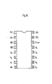
- Fig. 15 shows one practical example of the random access memory having a 64 K words X 1 bit construction on the basis of the second system shown in Fig. 4, and Fig. 16 illustrate terminal connections of the random access memory.
- reference symbols Ao to A 7 represent address input terminals in which symbols A 0 to A 6 concern to refresh addresses
- reference symbols D in and D ou t represent data input and data output terminals
- reference symbol WE represents a read/write control terminal
- reference symbol N/C represents a non-connection terminal.
- the device in the RAS/CAS cycle the device functions as a randam access memory having a 64 K wo rds X 1 bit construction, whereas in the new mode that can be realized according to the present invention (temporarily, let us call it "shift mode” or "consecutive access mode"), the device can realize a high-speed sequential access memory having a pseudo 8 K words X 8 bits construction, and moreover, the device can be packed in the conventional 16-pin package. Therefore, the illustrated device brings about remarkable effects and advantages both in functions and in practical mounting.
- memory cell arrays 51 of 126 rows X 256 columns are disposed in two sets, and there are provided two sets 52 of 256 sense/refresh amplifiers, one for each column.
- 128.row decoder units 53 for selecting a word line are disposed, one set for each array.
- 64 column decoder units 54 for transmitting and switching the memory cell information amplified by the sense/refresh amplifier 52 from the digit lines to 8 pairs of input/output data buses 56 in a unit of 8 pairs, further there is provided another decoder 55 associated with a shift register for selecting one pair out of the 8 pairs of input/output buses, and also there is provided an output buffer 57 for level- converting the memory cell information appearing on the one pair of input/output data buses 56 selected by the decoder 55 and transmitting the level-converted information externally.
- the row decoders 53 and the column decoders 54 receive row and column address codes, respectively, from 8-bit row and column address buffers 58 and 59 which have the functions of receiving row and column address signals, respectively, and converting them into binary address codes at the internal MOS level.
- a drive circuit for the above-mentioned principal function block is composed of a row address strobe signal generator, a column address strobe signal generator, a write/read control signal generator and a write data input buffer.
- the memory device according to the present invention which employs the multi-address system and the single 5V power supply system, can be packed in a 16-pin package without any difference in configuration from the conventional 64 K RAM, and hence, the effects of the improvements in the practical mounting of the memory device are remarkable.
- a series of operations of the memory device according to the present invention will be briefly explained with reference to Fig. 15.
- a series of necessary activation signals are generated.
- a row address input signal is introduced into 8 row address buffer units, and thereby binary address codes at the internal MOS level are produced.
- 7 bits are transmitted to the row decoder, in which selection/unselection operations of row decoder units are effected, and the remaining one bit is transmitted to the column decoder.
- one decoder in each set is selected, and in response to a word line drive clock generated upon sensing the selection/unselection of the row decoder units, the corresponding word line is selected, so that information of the memory cells connected to the selected word line is transmitted to the digit line sense amplifiers. Thereafter, when a word line drive clock is received, the sense amplifiers start amplification in response to a sense amplifier activation clock.
- the column address signal is introduced into 8 column address buffer units, where binary address codes at the internal MOS level are produced. Among the binary codes produced in these address buffer units, 5 bits are transmitted to the column decoder, where selection/unselection operations of the column decoder units are effected. The remaining three bits are fed to another decoder which selects one pair among 8 pairs of input/output buses.
- the column decoder 54 consisting of 64 column decoder units achieve switching of connection/disconnection between one unit of 8 pairs of input/output buses and digit line groups such consisting of 8 digit lines, in response to one bit of row address binary codes fed from the row address buffer and 5 bits of column address binsry codes fed from the column address buffer.
- the operation switches from the RAS/CAS cycle to the consecutive access mode relying upon the CAS clock only, then the selection/ unselection condition of the input/output data bus selecting decoder in the RAS/CAS cycle is introduced into the contained shift register, so that the 8 consecutive memory cells on the same word line starting from the memory cell selected in the RAS/CAS cycle can be accessed in a consecutive access mode.
- the consecutive access mode only the transfer in the shift register and the activation of the 8-bit decoder and the output buffer are necessitated.
- the memory device provided according to the present invention is an epoch-making device in that not only it is perfectly compatible to the conventional 16-pin mount 64 K words X 1 bit random access memory in the RAS/CAS cycle, but also a novel consecutive access mode cycle to be replaced for the heretofore known page mode can be realized, and a remarkable effect that the access time can be reduced to one-half is produced, and in that the memory device is characterized by the simplicity in use that there is no need to externally feed consecutive addresses.
Landscapes
- Engineering & Computer Science (AREA)
- Microelectronics & Electronic Packaging (AREA)
- Dram (AREA)
- Static Random-Access Memory (AREA)
Priority Applications (1)
| Application Number | Priority Date | Filing Date | Title |
|---|---|---|---|
| EP85103712A EP0162234A3 (de) | 1980-07-23 | 1981-07-23 | Speicheranordnung |
Applications Claiming Priority (3)
| Application Number | Priority Date | Filing Date | Title |
|---|---|---|---|
| JP10085080A JPS5727477A (en) | 1980-07-23 | 1980-07-23 | Memory circuit |
| JP100850/80 | 1980-07-23 | ||
| EP85103712A EP0162234A3 (de) | 1980-07-23 | 1981-07-23 | Speicheranordnung |
Related Parent Applications (2)
| Application Number | Title | Priority Date | Filing Date |
|---|---|---|---|
| EP81105827.0 Division | 1981-07-23 | ||
| EP81105827A Division EP0045063B1 (de) | 1980-07-23 | 1981-07-23 | Speicheranlage |
Publications (2)
| Publication Number | Publication Date |
|---|---|
| EP0162234A2 true EP0162234A2 (de) | 1985-11-27 |
| EP0162234A3 EP0162234A3 (de) | 1986-03-19 |
Family
ID=26096620
Family Applications (1)
| Application Number | Title | Priority Date | Filing Date |
|---|---|---|---|
| EP85103712A Withdrawn EP0162234A3 (de) | 1980-07-23 | 1981-07-23 | Speicheranordnung |
Country Status (1)
| Country | Link |
|---|---|
| EP (1) | EP0162234A3 (de) |
Cited By (8)
| Publication number | Priority date | Publication date | Assignee | Title |
|---|---|---|---|---|
| EP0290042A2 (de) * | 1987-05-06 | 1988-11-09 | Nec Corporation | Speicherschaltung mit serieller Adressierung |
| EP0262413B1 (de) * | 1986-09-04 | 1992-07-22 | Fujitsu Limited | Speichereinrichtung unter Verwendung von Adressenmultiplex |
| GB2300938A (en) * | 1995-05-15 | 1996-11-20 | Hyundai Electronics Industries Co Ltd | Burst page access unit for semiconductor memory device |
| US5587962A (en) * | 1987-12-23 | 1996-12-24 | Texas Instruments Incorporated | Memory circuit accommodating both serial and random access including an alternate address buffer register |
| GB2302974A (en) * | 1995-06-30 | 1997-02-05 | Hyundai Electronics Ind | A read only memory device |
| US5636176A (en) * | 1987-12-23 | 1997-06-03 | Texas Instruments Incorporated | Synchronous DRAM responsive to first and second clock signals |
| EP1117100A1 (de) * | 2000-01-13 | 2001-07-18 | Hewlett-Packard Company, A Delaware Corporation | Datenübertragungsverfahren mit Hilfe von Schieberegisterblöcken |
| KR101154560B1 (ko) * | 2007-06-07 | 2012-06-11 | 콸콤 인코포레이티드 | 이동 디바이스에 멀티미디어 컨텐츠를 제공하는 방법들 및 장치들 |
Citations (2)
| Publication number | Priority date | Publication date | Assignee | Title |
|---|---|---|---|---|
| US3930239A (en) | 1973-07-11 | 1975-12-30 | Philips Corp | Integrated memory |
| US3969706A (en) | 1974-10-08 | 1976-07-13 | Mostek Corporation | Dynamic random access memory misfet integrated circuit |
Family Cites Families (1)
| Publication number | Priority date | Publication date | Assignee | Title |
|---|---|---|---|---|
| US4106109A (en) * | 1977-02-01 | 1978-08-08 | Ncr Corporation | Random access memory system providing high-speed digital data output |
-
1981
- 1981-07-23 EP EP85103712A patent/EP0162234A3/de not_active Withdrawn
Patent Citations (2)
| Publication number | Priority date | Publication date | Assignee | Title |
|---|---|---|---|---|
| US3930239A (en) | 1973-07-11 | 1975-12-30 | Philips Corp | Integrated memory |
| US3969706A (en) | 1974-10-08 | 1976-07-13 | Mostek Corporation | Dynamic random access memory misfet integrated circuit |
Cited By (34)
| Publication number | Priority date | Publication date | Assignee | Title |
|---|---|---|---|---|
| EP0262413B1 (de) * | 1986-09-04 | 1992-07-22 | Fujitsu Limited | Speichereinrichtung unter Verwendung von Adressenmultiplex |
| EP0290042A2 (de) * | 1987-05-06 | 1988-11-09 | Nec Corporation | Speicherschaltung mit serieller Adressierung |
| EP0290042A3 (de) * | 1987-05-06 | 1990-02-07 | Nec Corporation | Speicherschaltung mit serieller Adressierung |
| US6732224B2 (en) | 1987-12-23 | 2004-05-04 | Texas Instrument Incorporated | System with control data buffer for transferring streams of data |
| US6732226B2 (en) | 1987-12-23 | 2004-05-04 | Texas Instruments Incorporated | Memory device for transferring streams of data |
| US6188635B1 (en) | 1987-12-23 | 2001-02-13 | Texas Instruments Incorporated | Process of synchronously writing data to a dynamic random access memory array |
| US5636176A (en) * | 1987-12-23 | 1997-06-03 | Texas Instruments Incorporated | Synchronous DRAM responsive to first and second clock signals |
| US5680369A (en) * | 1987-12-23 | 1997-10-21 | Texas Instruments Incorporated | Synchronous dynamic random access memory device |
| US5680368A (en) * | 1987-12-23 | 1997-10-21 | Texas Instruments Incorporated | Dram system with control data |
| US5680370A (en) * | 1987-12-23 | 1997-10-21 | Texas Instruments Incorporated | Synchronous DRAM device having a control data buffer |
| US5680358A (en) * | 1987-12-23 | 1997-10-21 | Texas Instruments Incorporated | System transferring streams of data |
| US5680367A (en) * | 1987-12-23 | 1997-10-21 | Texas Instruments Incorporated | Process for controlling writing data to a DRAM array |
| US5684753A (en) * | 1987-12-23 | 1997-11-04 | Texas Instruments Incorporated | Synchronous data transfer system |
| US5768205A (en) * | 1987-12-23 | 1998-06-16 | Texas Instruments Incorporated | Process of transfering streams of data to and from a random access memory device |
| US5805518A (en) * | 1987-12-23 | 1998-09-08 | Texas Instruments Incorporated | Memory circuit accommodating both serial and random access, having a synchronous DRAM device for writing and reading data |
| US6910096B2 (en) | 1987-12-23 | 2005-06-21 | Texas Instruments Incorporated | SDRAM with command decoder coupled to address registers |
| US6895465B2 (en) | 1987-12-23 | 2005-05-17 | Texas Instruments Incorporated | SDRAM with command decoder, address registers, multiplexer, and sequencer |
| US6748483B2 (en) | 1987-12-23 | 2004-06-08 | Texas Instruments Incorporated | Process of operating a DRAM system |
| US6738860B2 (en) | 1987-12-23 | 2004-05-18 | Texas Instruments Incorporated | Synchronous DRAM with control data buffer |
| US5587962A (en) * | 1987-12-23 | 1996-12-24 | Texas Instruments Incorporated | Memory circuit accommodating both serial and random access including an alternate address buffer register |
| US6662291B2 (en) | 1987-12-23 | 2003-12-09 | Texas Instruments Incorporated | Synchronous DRAM System with control data |
| US6735668B2 (en) | 1987-12-23 | 2004-05-11 | Texas Instruments Incorporated | Process of using a DRAM with address control data |
| US6728828B2 (en) | 1987-12-23 | 2004-04-27 | Texas Instruments Incorporated | Synchronous data transfer system |
| US6728829B2 (en) | 1987-12-23 | 2004-04-27 | Texas Instruments Incorporated | Synchronous DRAM system with control data |
| US6735667B2 (en) | 1987-12-23 | 2004-05-11 | Texas Instruments Incorporated | Synchronous data system with control data buffer |
| US6418078B2 (en) | 1987-12-23 | 2002-07-09 | Texas Instruments Incorporated | Synchronous DRAM device having a control data buffer |
| US6732225B2 (en) | 1987-12-23 | 2004-05-04 | Texas Instruments Incorporated | Process for controlling reading data from a DRAM array |
| GB2300938A (en) * | 1995-05-15 | 1996-11-20 | Hyundai Electronics Industries Co Ltd | Burst page access unit for semiconductor memory device |
| GB2300938B (en) * | 1995-05-15 | 1999-07-07 | Hyundai Electronics Ind | Burst page access unit for semiconductor memory device |
| GB2302974A (en) * | 1995-06-30 | 1997-02-05 | Hyundai Electronics Ind | A read only memory device |
| GB2302974B (en) * | 1995-06-30 | 1999-07-07 | Hyundai Electronics Ind | A read only memory device |
| US6728799B1 (en) | 2000-01-13 | 2004-04-27 | Hewlett-Packard Development Company, L.P. | Hybrid data I/O for memory applications |
| EP1117100A1 (de) * | 2000-01-13 | 2001-07-18 | Hewlett-Packard Company, A Delaware Corporation | Datenübertragungsverfahren mit Hilfe von Schieberegisterblöcken |
| KR101154560B1 (ko) * | 2007-06-07 | 2012-06-11 | 콸콤 인코포레이티드 | 이동 디바이스에 멀티미디어 컨텐츠를 제공하는 방법들 및 장치들 |
Also Published As
| Publication number | Publication date |
|---|---|
| EP0162234A3 (de) | 1986-03-19 |
Similar Documents
| Publication | Publication Date | Title |
|---|---|---|
| US4429375A (en) | Consecutive addressing of a semiconductor memory | |
| US4685089A (en) | High speed, low-power nibble mode circuitry for dynamic memory | |
| KR940000148B1 (ko) | 듀얼포트 반도체 기억장치 | |
| US4567579A (en) | Dynamic memory with high speed nibble mode | |
| EP0214180B1 (de) | Integrierter RAM-Speicher | |
| US5946265A (en) | Continuous burst EDO memory device | |
| US4562555A (en) | Semiconductor memory device | |
| US4788667A (en) | Semiconductor memory device having nibble mode function | |
| EP0143647A2 (de) | Halbleiterspeicheranordnung | |
| EP0056240B1 (de) | Speicheranordnung | |
| EP0969476B1 (de) | Integrierte Halbleiterspeicherschaltung | |
| US4754433A (en) | Dynamic ram having multiplexed twin I/O line pairs | |
| EP0145488A2 (de) | Halbleiterspeicheranordnung | |
| US4194130A (en) | Digital predecoding system | |
| US4241425A (en) | Organization for dynamic random access memory | |
| EP0017228B1 (de) | Speicheranordnung | |
| EP0191544A2 (de) | Speicher-CMOS-Dekodier- und Antriebsschaltung | |
| EP0290042A2 (de) | Speicherschaltung mit serieller Adressierung | |
| EP0162234A2 (de) | Speicheranordnung | |
| US4797573A (en) | Output circuit with improved timing control circuit | |
| US4831590A (en) | Semiconductor memory including an output latch having hysteresis characteristics | |
| EP0062547A2 (de) | Speicherschaltung | |
| US4354259A (en) | Semiconductor memory device having improved column selection structure | |
| KR0157289B1 (ko) | 컬럼 선택 신호 제어회로 | |
| US4485461A (en) | Memory circuit |
Legal Events
| Date | Code | Title | Description |
|---|---|---|---|
| PUAI | Public reference made under article 153(3) epc to a published international application that has entered the european phase |
Free format text: ORIGINAL CODE: 0009012 |
|
| 17P | Request for examination filed |
Effective date: 19850328 |
|
| AC | Divisional application: reference to earlier application |
Ref document number: 45063 Country of ref document: EP |
|
| AK | Designated contracting states |
Designated state(s): DE FR GB |
|
| PUAL | Search report despatched |
Free format text: ORIGINAL CODE: 0009013 |
|
| AK | Designated contracting states |
Kind code of ref document: A3 Designated state(s): DE FR GB |
|
| 17Q | First examination report despatched |
Effective date: 19881221 |
|
| STAA | Information on the status of an ep patent application or granted ep patent |
Free format text: STATUS: THE APPLICATION HAS BEEN WITHDRAWN |
|
| 18W | Application withdrawn |
Withdrawal date: 19930209 |
|
| RIN1 | Information on inventor provided before grant (corrected) |
Inventor name: MATSUE, SHIGEKI Inventor name: KOBAYASHI, SATORU |