EP0162048B1 - Package for coiled products and method of production thereof - Google Patents
Package for coiled products and method of production thereof Download PDFInfo
- Publication number
- EP0162048B1 EP0162048B1 EP84900652A EP84900652A EP0162048B1 EP 0162048 B1 EP0162048 B1 EP 0162048B1 EP 84900652 A EP84900652 A EP 84900652A EP 84900652 A EP84900652 A EP 84900652A EP 0162048 B1 EP0162048 B1 EP 0162048B1
- Authority
- EP
- European Patent Office
- Prior art keywords
- slab
- ring
- bands
- shaped bundle
- bundle
- Prior art date
- Legal status (The legal status is an assumption and is not a legal conclusion. Google has not performed a legal analysis and makes no representation as to the accuracy of the status listed.)
- Expired
Links
Images


Classifications
-
- B—PERFORMING OPERATIONS; TRANSPORTING
- B65—CONVEYING; PACKING; STORING; HANDLING THIN OR FILAMENTARY MATERIAL
- B65H—HANDLING THIN OR FILAMENTARY MATERIAL, e.g. SHEETS, WEBS, CABLES
- B65H75/00—Storing webs, tapes, or filamentary material, e.g. on reels
- B65H75/02—Cores, formers, supports, or holders for coiled, wound, or folded material, e.g. reels, spindles, bobbins, cop tubes, cans, mandrels or chucks
- B65H75/04—Kinds or types
- B65H75/08—Kinds or types of circular or polygonal cross-section
- B65H75/14—Kinds or types of circular or polygonal cross-section with two end flanges
- B65H75/143—Kinds or types of circular or polygonal cross-section with two end flanges at least one end flange being shaped to cover the windings
-
- B—PERFORMING OPERATIONS; TRANSPORTING
- B65—CONVEYING; PACKING; STORING; HANDLING THIN OR FILAMENTARY MATERIAL
- B65D—CONTAINERS FOR STORAGE OR TRANSPORT OF ARTICLES OR MATERIALS, e.g. BAGS, BARRELS, BOTTLES, BOXES, CANS, CARTONS, CRATES, DRUMS, JARS, TANKS, HOPPERS, FORWARDING CONTAINERS; ACCESSORIES, CLOSURES, OR FITTINGS THEREFOR; PACKAGING ELEMENTS; PACKAGES
- B65D85/00—Containers, packaging elements or packages, specially adapted for particular articles or materials
- B65D85/02—Containers, packaging elements or packages, specially adapted for particular articles or materials for annular articles
- B65D85/04—Containers, packaging elements or packages, specially adapted for particular articles or materials for annular articles for coils of wire, rope or hose
-
- B—PERFORMING OPERATIONS; TRANSPORTING
- B65—CONVEYING; PACKING; STORING; HANDLING THIN OR FILAMENTARY MATERIAL
- B65H—HANDLING THIN OR FILAMENTARY MATERIAL, e.g. SHEETS, WEBS, CABLES
- B65H55/00—Wound packages of filamentary material
Definitions
- the present invention relates to a package for coiled products such as ropes, hoses, flexible tubing, cables and similar kinds of products which are available by the metre coiled into a ring-shaped bundle, as well as to a method of manufacturing such a package, according to the preamble of claim 1 and 16, respectively.
- a cap-like protection element which consists of at least three independent ring segments which have a common cylindrical edge, so that these segments overlap each other in circumferential direction when said cylindrical edge is wound around said coil.
- the three radial inner edges of said segments are covered by a central ring which has an angular cross section.
- the central ring together with the protection element are then clamped to the coil by a plurality of flexible bands arranged in angular distance to each other.
- the protection element can be used for coils of different diameters.
- the package has to be destroyed in case that a certain set length of said sheet metal shall be drawn from the coil.
- the present invention aims at improving the handling of bundles for those kinds of products which are available and sold by the metre, wherein the bundle should not get loose when drawing a set length of a product:
- Products of said kind are usually manufactured in endless lengths, e.g. by extrusion, twisting or some analogous method of production.
- the finished product is fed out it is coiled on to a rotating coiling drum, reel or winder in a number of juxtaposed windings and in a number of superposed layers such that a ring-shaped bundle is shaped, the dimensions and weight of which are adjusted for enabling comfortable handling of the finished package.
- the feed out and coiling are stopped whereupon the coiled strands are fixed in position in relation to one another by tightening a strap or applying a strong adhesive piece of tape, e.g.
- the coiled product may then be cut and the ring-shaped bundle removed from the coiling drum or reel in the shape of a ring-shaped, form stable bundle containing the intended quantity of the coiled product.
- the bundle can then be delivered in this condition to the consumer place such as a building storehouse, a workshop or some other kind of working place where various lengths of the product are to be used.
- the embodiment of the package illustrated in Figs. 1-5 comprises a rigid supporting construction 2 disposed on one side of a ring-shaped bundle 1 of coiled products such as hoses, flexible tubing, cables etc.
- Said supporting construction 2 comprises two interacting annular and essentially flat slabs made of a rigid but light material.
- the slabs 3, 4 can thus be cut out from a fibre board, a plastic sheet or else be constructed of wood or similar materials.
- the inner annular slab 3 has an inside diameter essentially corresponding to the inside diameter of the ring-shaped bundle formed by the coiled product.
- the outerslab-4 preferably also being annular, is internally formed with a circular opening, the diameter of which is somewhat smaller than the outside diameter of the inner annular slab 3, such that said slab 3 can be brought to engage the outer slab 4 with overlap.
- the outer slab 4 and the inner slab 3 are fixed in relation to one another by means of a number of bands 5 of which there are four in the shown preferred embodiment, said bands being attached both to the outer slab 4 and to the inner slab 3 in a suitable manner, e.g. by means of a screw joint, rivet joint, adhesive joint or by glueing.
- the bands 5 which are made of flexible material of a strength sufficient to keep the strands included in the bundle rigidly tightened together, after said bands have been bent around the ring-shaped bundle and fixed to one another, project initially partly outwards from the outer slab 4 with a strand 5A and partly inwards from the inner slab 3 with a strand 5B. Said strands 5A and 5B are of sufficient length to overlap one another after having been bent around the ring-shaped bundle to enable fixing to one another by riveting, stapling, glueing or by means of hook and loop fastener tape or the like.
- the bands 5 may consist of plastic tape, glass-fibre reinforced plastic bands, bands of textile or strong paper or cardboard.
- the bands 5 may also be made of elastic material, e.g. rubber material.
- the bands are folded around the ring-shaped bundle, the bands 5, on the side of the bundle opposite the slabs 3,4 being fixed to one another e.g. by riveting or stapling, as indicated by the reference 7 in Figs. 8 and 9.
- the finished package will form a stable and rigid ring-shaped bundle which can easily be handled and transported from the place where it is packaged to the place where it is to be consumed, which may be a building storehouse, a workshop or some other place of work where a required length of the coiled product is to be used.
- Fig. 2 illustrates the taking out the coiled product from the package.
- the package is here shown resting on a horizontal bedding with the supporting construction consisting of the annular slabs 3 and 4 being turned upwards.
- the bands 5 are cut at the position where the annular slabs 3 and 4 overlap one another.
- the inner slab 3 is raised from the outer slab 4 to an adequate degree to permit the hose to be passed out between the inner slab 3 and the outer slab 4.
- the hose can then be uncoiled counter-clockwise and in this process is guided along the outside diameter of the annuler inner slab 3.
- the hose is cut. Should an excessive length have been uncoiled this excess length can be easily recoiled through the interspace between the annular inner slab 3 and the outer slab 4.
- the package according to the invention will keep the shape of the ring-shaped bundle essentially intact when the hose is being uncoiled and will prevent the bundle from expanding or tangling of the coiled layers.
- Fig. 2 the package is shown as resting on a horizontal bedding but this is not a prerequisite for taking the product out from the package. It is thus expedient to place the package in vertical position e.g.
- Package of various dimensions of e.g. hose or flexible tubing are suitably given such a dimension that the inside diameter of the package of the largest dimension will correspond with some clearance to the outside diameter of the package of the next lower dimension such that the packages can be hung on a wall with the packages disposed inside one another with the largest hose or tube dimension outermost and the smaller dimensions innermost.
- the package can also be used for laying out e.g. flexible tubing or cable and can then be rolled along the intended laying- out distance.
- the annular inner slab 3 is clamped to the outer slab 4 by riveting, stapling, screwing, glueing etc. the bands 5 to the outer slab 4 as well as to the inner slab 3 with the band ends 5A and 5B projecting each in its direction from the annular slabs.
- the band 5 can comprise two separate bands of which one engages the outer slab 4 projecting out therefrom and the other one engages the inner slab 3 projecting inwards therefrom. It is, however, a disadvantage of the latter embodiment that when the slabs are positioned against the ring-shaped bundle 1 it is essential that the slabs be centred in relation to one another such that they will overlap one another with a suitable degree of overlapping.
- the coiled product is uncoiled starting from the inside of the bundle.
- the radial width of the inner slab 3 is substantially smaller than the corresponding width of the outer slab.
- the outer slab 4 then also immediately engages one side of the bundle whereas the inner slab 3 engaging the outer slab on the side thereof turning away from the ring-shaped bundle.
- the package may also be formed, however, to allow uncoiling of the coiled product starting from the outside of the bundle.
- the package is then modified to the respect that the annular inner slab is given a substantially larger radial width than the corresponding width of the outer slab 4.
- the inner slab 3 will then also directly engage the outer side of the tube-shaped bundle, the annular outer slab 4 instead being made to overlap the inner slab on the side thereof turning away from the ring-shaped bundle.
- the inner slab 3 as well as the outer slab 4 have a circular annular shape. It is no prerequisite, however, for the invention that the outer slab 4 be of a circular outward shape, but it may very well be of another shape, e.g. square-shaped.
- the inner slab 3, however, must always have a circular annular shape and the opening in the outer slab 4 must also be circular.
- Figs. 1-5 is advantageous in so far as it is conveniently produced in immediate connection with the manufacture of the products to be coiled and the invention also relates to a preferred method of manufacture of the package as will be schematically illustrated with reference to Figs. 5A, B-9.
- Figs. 5A and 58 illustrate in an utterly schematic manner a coiling drum or reel which may be of any prior art type but which is shown to include a hub 8 with spikes 9 projecting radially from the hub and each carrying angular supporting means 10 together forming a cylindrical coiling matrix when rotated.
- the coiling drum or reel is preferably motor powered for rotation at a periphery speed corresponding to the feed-out speed of the product to be coiled.
- the carrying construction 2 included in the package is placed on the coiling matrix at one end thereof and in a plane which is perpendicular to the axis of rotation of the coiling matrix.
- the outer slab 4 and the inner slab 3, clamped by means of the bands 5 are placed on the coiling matrix, the inner annular slab 3 engaging the vertical legs of the angular carrying means 10 of the coiling matrix, the bands 5 disposed on the side of the slabs 3 and 4 facing said angular means 10 and the band ends 5A projecting out from the outer slab and the band ends 5B projecting inwards from the inner slab 3.
- the end of the fed-out product intended for coiling is then clamped in any convenient manner to the coiling matrix in proximity to the supporting construction 2 placed thereon.
- the coiling drum or reel is then made to rotate at a periphery speed of the product being fed out.
- the coiling is performed with a predetermined number of juxtaposed strands and a predetermined number of superposed layers as illustrated schematically in Figs. 7 and 8.
- the coiling is stopped, whereupon the bands 5A and 5B are bent around the ring-shaped bundle, and, in this process, are brought to overlap one another after which the band ends 5A and 5B are clamped to one another by riveting as indicated by the reference number 7 in Figs. 8 and 9 or by glueing or by means of so called hook and loop fastener tape, or in some other suitable manner.
- the finished package is removed from the coiling drum or reel, whereupon the supporting construction 2 for a new package is placed on the coiling matrix and the coiling process described above is repeated.
- a variant of the package according to the invention is illustrated which is particularly well suited for use when the coiled products are in the form of e.g. flexible tubing, such as plastic tubing having relatively coarse dimensions.
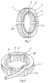
- the package according to Figs. 10 and 11 includes a rigid supporting construction 2 which is disposed on one side of a ring-shaped bundle 1 of coiled products, preferably flexible plastic tubing.
- a supporting construction 2 is disposed comprising two juxtaposed substantially concentrically disposed annular supporting members, the inner annular supporting member 11 and the outer annular supporting member 12.
- the supporting members 11 and 12 thus form circular rings and are conveniently manufactured from tubing which has been bent into annular shape, preferably plastic tubing.
- the annular supporting members 11, 12 are mutually fixed to one another at least at three points along the periphery of the annular supporting members.
- the connection between the supporting members 11, 12 consists of flexible members and preferably comprises flexible bands 13, e.g. strong plastic bands, glass fibre reinforced plastic bands etc.
- One end of the band 13 is clamped to the inner annular supporting member, as shown at 14 in Fig. 11.
- the clamping can be achieved by riveting or screw-fixing the band 13, or the band end can be inserted through an opening in the tubular supporting member 11 and be locked on the inside of the tubular profile by means of a bead or the like.
- the band 13 then extends radially outwards along the upper side of the ring-shaped bundle 1, but underneath the outer annular supporting member 12.
- the band 13 then extends around the peripheral cross section of the bundle 1, back up over the inner annular supporting member 11 and, with its other end, is clamped to the outer supporting member 12.
- the clamping of the band to the supporting member 12 is conveniently performed in the same manner as the clamping to the inner annular supporting member 11.
- the band 13 is suitably divided into two parts 13A and 13B, one part 13A with one of its ends being clamped to the inner annular supporting member 11, and the other part 13B with its end being clamped to the outer annular supporting member 12, the bands portions 13A, 13B being attached to one another by means of a suitable locking device 15 of a prior art construction, e.g. of the type bull-dog grip or stretcher, which partly connects the band portion 13A, 13B to one another and partly enables tightening of the sling which the band 13 forms in mounted condition.
- a suitable locking device 15 of a prior art construction, e.g. of the type bull-dog grip or stretcher
- the number of band slings 13 should, as already mentioned, be at least three, evenly spaced along the periphery of the annular bundle, but suitably the number of band slings 13 should exceed this number, e.g. six band slings, as shown in Fig. 10.
- the supporting construction 2 is mounted on the ring-shaped bundle 1 by disposing the inner annular supporting member 11 and the outer annular supporting member 12 on one side of the ring-shaped bundle 1 and orienting them substantially concentrically in relation on one another as well as in relation to the ring-shaped bundle 1.
- the band portions 13A, 13B are then arranged around the peripheral cross section of the ring-shaped bundle 1 and are connected to one another by means of the band stretcher 15, whereupon the band 13 is tightened by means of the band stretcher 15.
- the ring-shaped bundle 1 is then ready to be delivered to place of work or some other place of consumption.
- the inner free end of the tubing in the bundle is moved up over the inner annular supporting member 11, whereupon the outer annular supporting member 12, which is movable perpendicularly to the level of the supporting members, is lifted to a sufficient degree in order to permit the tubing to be passed under the outer annular supporting member 12 and out from the ring-shaped bundle 1 as illustrated in Fig. 10.
- the desired length of tubing can be taken out from the ring-shaped bundle 1 by "uncoiling" the tubing from the inner of the ring-shaped bundle, according to Fig. 10 in dock-wise direction. If the ring-shaped bundle e.g.
- the inner ring 11 and the outer ring 12 are radially spaced. They are spaced in such a manner that the tubing to be fed out can be conveniently passed down into the interspace and below the raised outer annular member 12.
- the concept of the invention may also be applied by superposing the rings, provided that said rings are of a dimension that will not allow them to be passed through one another. The outside diameter of the superposed ring must therefore exceed the inside diameter of the underlying ring.
Landscapes
- Engineering & Computer Science (AREA)
- Mechanical Engineering (AREA)
- Packaging Of Annular Or Rod-Shaped Articles, Wearing Apparel, Cassettes, Or The Like (AREA)
- Auxiliary Devices For And Details Of Packaging Control (AREA)
- Packaging Of Machine Parts And Wound Products (AREA)
- Transition And Organic Metals Composition Catalysts For Addition Polymerization (AREA)
- Compression Or Coding Systems Of Tv Signals (AREA)
- Packages (AREA)
- Making Paper Articles (AREA)
- Wrappers (AREA)
- Processing And Handling Of Plastics And Other Materials For Molding In General (AREA)
Abstract
Description
- The present invention relates to a package for coiled products such as ropes, hoses, flexible tubing, cables and similar kinds of products which are available by the metre coiled into a ring-shaped bundle, as well as to a method of manufacturing such a package, according to the preamble of
claim 1 and 16, respectively. - From DE-A-2 811 608 a package of the above mentioned kind is known. The design of this package is adapted to the transport of coils made of sheet metal in order to protect the coils from impacts and corrosive weather influences.
- To this end a cap-like protection element is provided which consists of at least three independent ring segments which have a common cylindrical edge, so that these segments overlap each other in circumferential direction when said cylindrical edge is wound around said coil. The three radial inner edges of said segments are covered by a central ring which has an angular cross section. The central ring together with the protection element are then clamped to the coil by a plurality of flexible bands arranged in angular distance to each other.
- With this construction the protection element can be used for coils of different diameters. However, the package has to be destroyed in case that a certain set length of said sheet metal shall be drawn from the coil.
- The present invention aims at improving the handling of bundles for those kinds of products which are available and sold by the metre, wherein the bundle should not get loose when drawing a set length of a product:
- Products of said kind are usually manufactured in endless lengths, e.g. by extrusion, twisting or some analogous method of production. As the finished product is fed out it is coiled on to a rotating coiling drum, reel or winder in a number of juxtaposed windings and in a number of superposed layers such that a ring-shaped bundle is shaped, the dimensions and weight of which are adjusted for enabling comfortable handling of the finished package. When the bundle shaped by coiling has reached the set dimensions the feed out and coiling are stopped whereupon the coiled strands are fixed in position in relation to one another by tightening a strap or applying a strong adhesive piece of tape, e.g. plastic tape, wrapping and tying a string or the like across the coil direction, around the ring section of the ring-shaped bundle at spaced apart positions along the ring-shaped bundle. The coiled product may then be cut and the ring-shaped bundle removed from the coiling drum or reel in the shape of a ring-shaped, form stable bundle containing the intended quantity of the coiled product. The bundle can then be delivered in this condition to the consumer place such as a building storehouse, a workshop or some other kind of working place where various lengths of the product are to be used.
- Before a certain set length of the product can be drawn from the bundle the cord, tape or string fixing the bundle must be cut. This will result in the ring-shaped bundle getting looser. The strands coiled up in ring-shape will no longer be held together which may result in that the bundle expands and consequently requires more space. One may also risk tangling the coiled strands and rendering renewed dispensing of a desired length more difficult.
- It is the object of the present invention to eliminate said drawbacks and it thus relates to a package for coiled products which will not only ensure required rigidity in the products coiled up into ring-shaped bundle in order to enable the transportation of the bundle as a rigid unit, but which will also allow the dispensing of required lengths of the product from the bundle without impairing said rigidity. It is a further object of the invention to provide a package of said kind which is simple in construction and which can consequently be manufactured at a low cost. Still another object of the invention is to provide a package of said kind which is simple to use and which also permits refeeding into the package of an excessive length of the product drawn from the package. Another object of the invention is to provide a package which is rigid enough to permit the rolling of the package as a wheel over a bedding simultaneously as the product is being fed out from the package, e.g. when laying out tubing or cable.
- It is also an object of the invention to provide a method of production of said package which permits the manufacture thereof in immediate connection with the coiling of the product at the place of its manufacture.
- The objects mentioned above are achieved by providing an embodiment according to the characteristics of
main claims 1 and 16 and the measures defined in the appended claims. - The invention will be described below with respect to two different examples of embodiment illustrated in the accompanying drawings in which
- Fig. 1 is a perspective view of a first embodiment of the finished package containing a set number of windings of the coiled product in the shape of a ring-shaped bundle,
- Fig. 2 is a perspective view illustrating the drawing out of a length of the product from the package shown in Fig. 1,
- Fig. 3 shows a front view of the simple components of which the package according to Fig. 1 is essentially constructed,
- Fig. 4 is a cross section through the parts of the package shown in Fig. 3,
- Fig. 5A and 5B as well as Figs. 6-9 illustrate in an utterly schematic manner the various process- steps in the method according to the invention of manufacturing the package according to Figs. 1-4,
- Fig. 10 is a plan view of a second embodiment of the package according to the invention,
- Fig. 11 is a partial section through the package shown in Fig. 10 taken as shown at I-I in Fig. 10.
- The embodiment of the package illustrated in Figs. 1-5 comprises a rigid supporting
construction 2 disposed on one side of a ring-shaped bundle 1 of coiled products such as hoses, flexible tubing, cables etc. Said supportingconstruction 2 comprises two interacting annular and essentially flat slabs made of a rigid but light material. Theslabs annular slab 3 has an inside diameter essentially corresponding to the inside diameter of the ring-shaped bundle formed by the coiled product. The outerslab-4, preferably also being annular, is internally formed with a circular opening, the diameter of which is somewhat smaller than the outside diameter of the innerannular slab 3, such that saidslab 3 can be brought to engage theouter slab 4 with overlap. As particularly appears from Fig. 3 theouter slab 4 and theinner slab 3 are fixed in relation to one another by means of a number ofbands 5 of which there are four in the shown preferred embodiment, said bands being attached both to theouter slab 4 and to theinner slab 3 in a suitable manner, e.g. by means of a screw joint, rivet joint, adhesive joint or by glueing. Thebands 5 which are made of flexible material of a strength sufficient to keep the strands included in the bundle rigidly tightened together, after said bands have been bent around the ring-shaped bundle and fixed to one another, project initially partly outwards from theouter slab 4 with astrand 5A and partly inwards from theinner slab 3 with a strand 5B. Saidstrands bands 5 may consist of plastic tape, glass-fibre reinforced plastic bands, bands of textile or strong paper or cardboard. Thebands 5 may also be made of elastic material, e.g. rubber material. As particularly appears from Fig. 1 the bands are folded around the ring-shaped bundle, thebands 5, on the side of the bundle opposite theslabs reference 7 in Figs. 8 and 9. - As particularly appears from Figs. 1 and 2 the finished package will form a stable and rigid ring-shaped bundle which can easily be handled and transported from the place where it is packaged to the place where it is to be consumed, which may be a building storehouse, a workshop or some other place of work where a required length of the coiled product is to be used.
- Fig. 2 illustrates the taking out the coiled product from the package. The package is here shown resting on a horizontal bedding with the supporting construction consisting of the
annular slabs bands 5 are cut at the position where theannular slabs inner slab 3 is raised from theouter slab 4 to an adequate degree to permit the hose to be passed out between theinner slab 3 and theouter slab 4. - The hose can then be uncoiled counter-clockwise and in this process is guided along the outside diameter of the annuler
inner slab 3. When a sufficient length has been uncoiled, the hose is cut. Should an excessive length have been uncoiled this excess length can be easily recoiled through the interspace between the annularinner slab 3 and theouter slab 4. It is obvious that the package according to the invention will keep the shape of the ring-shaped bundle essentially intact when the hose is being uncoiled and will prevent the bundle from expanding or tangling of the coiled layers. In Fig. 2 the package is shown as resting on a horizontal bedding but this is not a prerequisite for taking the product out from the package. It is thus expedient to place the package in vertical position e.g. hung on a wall where the package will occupy minimum space which may be particularly advantageous in premises of restricted space, e.g. building storehouses and the like. Package of various dimensions of e.g. hose or flexible tubing are suitably given such a dimension that the inside diameter of the package of the largest dimension will correspond with some clearance to the outside diameter of the package of the next lower dimension such that the packages can be hung on a wall with the packages disposed inside one another with the largest hose or tube dimension outermost and the smaller dimensions innermost. By providing the carrying construction built from the annular slabs with sufficient rigidity the package can also be used for laying out e.g. flexible tubing or cable and can then be rolled along the intended laying- out distance. - In the embodiment shown in Figs. 1-5 the annular
inner slab 3 is clamped to theouter slab 4 by riveting, stapling, screwing, glueing etc. thebands 5 to theouter slab 4 as well as to theinner slab 3 with theband ends band 5, however, can comprise two separate bands of which one engages theouter slab 4 projecting out therefrom and the other one engages theinner slab 3 projecting inwards therefrom. It is, however, a disadvantage of the latter embodiment that when the slabs are positioned against the ring-shaped bundle 1 it is essential that the slabs be centred in relation to one another such that they will overlap one another with a suitable degree of overlapping. Once the band ends 5A and 5B are fixed to one another on the opposite side of the ring-shaped bundle, the bands are kept in a centred position in relation to one another. - In the embodiment shown in Figs. 1-5 the coiled product is uncoiled starting from the inside of the bundle. In order to facilitate this the radial width of the
inner slab 3 is substantially smaller than the corresponding width of the outer slab. Theouter slab 4 then also immediately engages one side of the bundle whereas theinner slab 3 engaging the outer slab on the side thereof turning away from the ring-shaped bundle. The package may also be formed, however, to allow uncoiling of the coiled product starting from the outside of the bundle. The package is then modified to the respect that the annular inner slab is given a substantially larger radial width than the corresponding width of theouter slab 4. Theinner slab 3 will then also directly engage the outer side of the tube-shaped bundle, the annularouter slab 4 instead being made to overlap the inner slab on the side thereof turning away from the ring-shaped bundle. - In the embodiment according to Figs. 1-5 the
inner slab 3 as well as theouter slab 4 have a circular annular shape. It is no prerequisite, however, for the invention that theouter slab 4 be of a circular outward shape, but it may very well be of another shape, e.g. square-shaped. Theinner slab 3, however, must always have a circular annular shape and the opening in theouter slab 4 must also be circular. - As already pointed out the package according to Figs. 1-5 is advantageous in so far as it is conveniently produced in immediate connection with the manufacture of the products to be coiled and the invention also relates to a preferred method of manufacture of the package as will be schematically illustrated with reference to Figs. 5A, B-9.
- Figs. 5A and 58 illustrate in an utterly schematic manner a coiling drum or reel which may be of any prior art type but which is shown to include a
hub 8 withspikes 9 projecting radially from the hub and each carrying angular supporting means 10 together forming a cylindrical coiling matrix when rotated. The coiling drum or reel is preferably motor powered for rotation at a periphery speed corresponding to the feed-out speed of the product to be coiled. - Before the coiling of the product on to the drum or reel is started the carrying
construction 2 included in the package is placed on the coiling matrix at one end thereof and in a plane which is perpendicular to the axis of rotation of the coiling matrix. As will appear from the schematical Figure 6 theouter slab 4 and theinner slab 3, clamped by means of thebands 5, are placed on the coiling matrix, the innerannular slab 3 engaging the vertical legs of the angular carrying means 10 of the coiling matrix, thebands 5 disposed on the side of theslabs inner slab 3. - The end of the fed-out product intended for coiling is then clamped in any convenient manner to the coiling matrix in proximity to the supporting
construction 2 placed thereon. The coiling drum or reel is then made to rotate at a periphery speed of the product being fed out. The coiling is performed with a predetermined number of juxtaposed strands and a predetermined number of superposed layers as illustrated schematically in Figs. 7 and 8. When the predeterminated length has been coiled the coiling is stopped, whereupon thebands reference number 7 in Figs. 8 and 9 or by glueing or by means of so called hook and loop fastener tape, or in some other suitable manner. - After the band ends 5A and 5B have been folded around the ring-shaped bundle and clamped to one another, the finished package is removed from the coiling drum or reel, whereupon the supporting
construction 2 for a new package is placed on the coiling matrix and the coiling process described above is repeated. - In Figs. 10 and 11 a variant of the package according to the invention is illustrated which is particularly well suited for use when the coiled products are in the form of e.g. flexible tubing, such as plastic tubing having relatively coarse dimensions. As in the variant described in connection with Figs. 1-5 the package according to Figs. 10 and 11 includes a rigid supporting
construction 2 which is disposed on one side of a ring-shapedbundle 1 of coiled products, preferably flexible plastic tubing. On one side of the ring-shaped bundle 1 a supportingconstruction 2 is disposed comprising two juxtaposed substantially concentrically disposed annular supporting members, the innerannular supporting member 11 and the outerannular supporting member 12. The supportingmembers members members flexible bands 13, e.g. strong plastic bands, glass fibre reinforced plastic bands etc. One end of theband 13 is clamped to the inner annular supporting member, as shown at 14 in Fig. 11. The clamping can be achieved by riveting or screw-fixing theband 13, or the band end can be inserted through an opening in thetubular supporting member 11 and be locked on the inside of the tubular profile by means of a bead or the like. Theband 13 then extends radially outwards along the upper side of the ring-shapedbundle 1, but underneath the outerannular supporting member 12. Theband 13 then extends around the peripheral cross section of thebundle 1, back up over the innerannular supporting member 11 and, with its other end, is clamped to the outer supportingmember 12. The clamping of the band to the supportingmember 12 is conveniently performed in the same manner as the clamping to the innerannular supporting member 11. Theband 13 is suitably divided into twoparts part 13A with one of its ends being clamped to the innerannular supporting member 11, and theother part 13B with its end being clamped to the outerannular supporting member 12, thebands portions suitable locking device 15 of a prior art construction, e.g. of the type bull-dog grip or stretcher, which partly connects theband portion band 13 forms in mounted condition. The number of band slings 13 should, as already mentioned, be at least three, evenly spaced along the periphery of the annular bundle, but suitably the number of band slings 13 should exceed this number, e.g. six band slings, as shown in Fig. 10. - The supporting
construction 2 is mounted on the ring-shapedbundle 1 by disposing the innerannular supporting member 11 and the outerannular supporting member 12 on one side of the ring-shapedbundle 1 and orienting them substantially concentrically in relation on one another as well as in relation to the ring-shapedbundle 1. Theband portions bundle 1 and are connected to one another by means of theband stretcher 15, whereupon theband 13 is tightened by means of theband stretcher 15. The ring-shapedbundle 1 is then ready to be delivered to place of work or some other place of consumption. - When a required length of tubing is to be taken out from the
bundle 1 the inner free end of the tubing in the bundle is moved up over the innerannular supporting member 11, whereupon the outerannular supporting member 12, which is movable perpendicularly to the level of the supporting members, is lifted to a sufficient degree in order to permit the tubing to be passed under the outerannular supporting member 12 and out from the ring-shapedbundle 1 as illustrated in Fig. 10. The desired length of tubing can be taken out from the ring-shapedbundle 1 by "uncoiling" the tubing from the inner of the ring-shaped bundle, according to Fig. 10 in dock-wise direction. If the ring-shaped bundle e.g. rests on a rotatable stand a corresponding effect can be achieved by pulling out the tubing end passed under the outerannular supporting member 12, the ring-shaped bundle being caused to rotate on its stand in counter dock-wise direction according to Fig. 10. The outer and inner annular supportingmembers bands 13 will ensure throughout the process that the ring-shaped bundle is kept at a desirable rigidity. After a sufficient number of coiled layers have been uncoiled from the package the band slings 13 are suitably tightened by means of theband stretchers 15. - In the preferred embodiment illustrated in Figs. 10 and 11 the
inner ring 11 and theouter ring 12 are radially spaced. They are spaced in such a manner that the tubing to be fed out can be conveniently passed down into the interspace and below the raised outerannular member 12. Even if the embodiment shown in Figs. 10 and 11 where one annular member, theouter ring 12, is disposed radially outside the other annular member, theinner ring 11, the concept of the invention may also be applied by superposing the rings, provided that said rings are of a dimension that will not allow them to be passed through one another. The outside diameter of the superposed ring must therefore exceed the inside diameter of the underlying ring. In the example of embodiment shown in Figs. 10 and 11 the length of tubing is uncoiled radially from within and outwards. It is obvious, however, that this order may be reversed so that the uncoiling is instead performed from the outside periphery and inwards. The only change required in so doing, as compared with the embodiment according to Fig. 11 being that theband 13 from its attachment at theannular member 12 is pulled in radially, below theannular member 11 and then around the peripheral cross section of the ring-shaped package and back radially inwards over theannular member 11 to be clamped to theannular member 11. The embodiment according to the invention shown in Figs. 10 and 11 has proved, as already noted, to be particularly expedient in bundles of tubing containing coarse and heavy plastic tubing and is furthermore advantageous owing to its simplicity of construction.
Claims (16)
Priority Applications (1)
| Application Number | Priority Date | Filing Date | Title |
|---|---|---|---|
| AT84900652T ATE34359T1 (en) | 1983-01-26 | 1984-01-26 | PACKAGING FOR ROLLED PRODUCTS AND MANUFACTURING PROCESS. |
Applications Claiming Priority (2)
| Application Number | Priority Date | Filing Date | Title |
|---|---|---|---|
| SE8300383A SE454981B (en) | 1983-01-26 | 1983-01-26 | PACKAGING FOR INVENTIBLE PRODUCTS AND SET FOR ITS MANUFACTURING |
| SE8300383 | 1983-11-08 |
Publications (2)
| Publication Number | Publication Date |
|---|---|
| EP0162048A1 EP0162048A1 (en) | 1985-11-27 |
| EP0162048B1 true EP0162048B1 (en) | 1988-05-18 |
Family
ID=20349763
Family Applications (1)
| Application Number | Title | Priority Date | Filing Date |
|---|---|---|---|
| EP84900652A Expired EP0162048B1 (en) | 1983-01-26 | 1984-01-26 | Package for coiled products and method of production thereof |
Country Status (9)
| Country | Link |
|---|---|
| US (1) | US4572370A (en) |
| EP (1) | EP0162048B1 (en) |
| AT (1) | ATE34359T1 (en) |
| DE (1) | DE3471289D1 (en) |
| DK (1) | DK151095C (en) |
| FI (1) | FI854393A (en) |
| NO (1) | NO160703C (en) |
| SE (1) | SE454981B (en) |
| WO (1) | WO1984002893A1 (en) |
Families Citing this family (21)
| Publication number | Priority date | Publication date | Assignee | Title |
|---|---|---|---|---|
| RU1804426C (en) * | 1986-05-02 | 1993-03-23 | Фераг Аг | Apparatus for winding printed production, fed by cascades, into portable rolls and binding obtained rolls |
| SE9001334D0 (en) * | 1990-04-12 | 1990-04-12 | Ulf Lindstrand | CABLE DRUM |
| US5078269A (en) * | 1990-06-07 | 1992-01-07 | Group Dekko International, Inc. | Wire shipping and dispensing container |
| SE470017B (en) * | 1991-05-27 | 1993-10-25 | Ulvator Ab | Tools for mounting on a package containing a coil of eg cable or cable |
| US5238105A (en) * | 1991-09-23 | 1993-08-24 | Smiley Howard F | Container |
| US5163554A (en) * | 1992-01-10 | 1992-11-17 | Merit Medical Systems, Inc. | System and method for packaging coils of tubing |
| US5314070A (en) * | 1992-12-16 | 1994-05-24 | Welch Allyn, Inc. | Case for flexible borescope and endoscope insertion tubes |
| US5309604A (en) * | 1993-03-11 | 1994-05-10 | Merit Medical Systems, Inc. | Coiling/uncoiling device for tubing |
| US6135282A (en) * | 1997-12-18 | 2000-10-24 | Dayco Products, Inc. | Hose package and method of making and blank comprising same |
| US6705163B1 (en) * | 1998-07-16 | 2004-03-16 | Morrison Bros. Company | Liquid level gauge and spool lock therefor |
| ES2222024T3 (en) * | 1999-08-05 | 2005-01-16 | Sica S.P.A. | METHOD AND MACHINE TO PACK ROLLS, CONFIGURED RING TYPE, OF A FLEXIBLE AND LONG ELEMENT. |
| US6511573B1 (en) * | 2000-05-30 | 2003-01-28 | Minnesota Medical Development, Inc. | Machines for forming tubular containers |
| US6581763B2 (en) * | 2001-10-18 | 2003-06-24 | Olympic General Corporation | Packaging system for coiled goods |
| US20050129108A1 (en) * | 2003-01-29 | 2005-06-16 | Everest Vit, Inc. | Remote video inspection system |
| EP1909633B1 (en) * | 2005-06-24 | 2011-11-23 | GE Inspection Technologies, LP | Insertion tube storage carousel |
| US7918414B1 (en) | 2007-02-23 | 2011-04-05 | Davis Edward W | Method and apparatus for managing wire rope slings |
| DE202011052330U1 (en) * | 2011-12-16 | 2013-03-19 | Uponor Innovation Ab | Unwinding device for a pipe collar and pipe collar |
| US9073727B2 (en) * | 2011-12-19 | 2015-07-07 | Apple Inc. | Systems and methods for hanking a cable |
| US20140061356A1 (en) * | 2012-08-31 | 2014-03-06 | Adc Telecommunications, Inc. | Cable packing systems and methods |
| CN111959860B (en) * | 2020-08-18 | 2021-09-17 | 新昌县知贝机械有限公司 | Annular reinforcing steel bar arranging and binding device |
| US20230211942A1 (en) * | 2021-12-30 | 2023-07-06 | RMX Industries | Weather resistant plastic packaging |
Family Cites Families (14)
| Publication number | Priority date | Publication date | Assignee | Title |
|---|---|---|---|---|
| US2527842A (en) * | 1946-02-07 | 1950-10-31 | Acme Steel Co | Spool for flexible binders |
| CH280703A (en) * | 1949-12-23 | 1952-01-31 | Daetwyler Ag Schweizerische Dr | Container with wire ring inside. |
| US2943732A (en) * | 1956-04-09 | 1960-07-05 | Coulter & Mckenzie Machine Co | Package and container forming part thereof |
| US3446419A (en) * | 1967-10-23 | 1969-05-27 | St Regis Paper Co | Coil package |
| US3524538A (en) * | 1969-01-21 | 1970-08-18 | Harold Marlowe | Ring package |
| US3729092A (en) * | 1971-03-12 | 1973-04-24 | W Marcell | Unwind support for coiled wire |
| US3910409A (en) * | 1973-08-02 | 1975-10-07 | Gen Electric | Circline lamp carton |
| DE2436150C2 (en) * | 1974-07-26 | 1985-01-03 | Rudolf 8057 Eching Jocham | Container for storing film spools |
| SE404347B (en) * | 1976-03-10 | 1978-10-02 | Skarwell Ab | PACKAGING FOR IN ROLL SHAPE PACKED CABLE OR SIMILAR |
| FR2383846A1 (en) * | 1977-03-18 | 1978-10-13 | Nakache Robert | CYLINDRICAL COIL PROTECTION AND PACKAGING KIT |
| NL7706511A (en) * | 1977-06-14 | 1978-12-18 | Philips Nv | PACKAGING FOR TUBULAR LAMPS. |
| CH628303A5 (en) * | 1978-10-25 | 1982-02-26 | Gefitec Sa | BOX FOR STORING AND PROTECTING A COIL FOR CINEMATOGRAPHIC FILM OR MAGNETIC TAPE. |
| FR2483894A1 (en) * | 1980-06-06 | 1981-12-11 | Sopagil Sarl | PACKAGING MATERIAL FOR THE STORAGE OF SPINNING MATERIALS IN THE FORM OF PARALLEL SPIRE WINDING |
| US4513864A (en) * | 1983-01-18 | 1985-04-30 | Signode Paper Products Company | Interior core protector |
-
1983
- 1983-01-26 SE SE8300383A patent/SE454981B/en not_active IP Right Cessation
-
1984
- 1984-01-26 DE DE8484900652T patent/DE3471289D1/en not_active Expired
- 1984-01-26 WO PCT/SE1984/000024 patent/WO1984002893A1/en active IP Right Grant
- 1984-01-26 EP EP84900652A patent/EP0162048B1/en not_active Expired
- 1984-01-26 US US06/662,412 patent/US4572370A/en not_active Expired - Fee Related
- 1984-01-26 AT AT84900652T patent/ATE34359T1/en not_active IP Right Cessation
- 1984-09-21 NO NO84843779A patent/NO160703C/en unknown
- 1984-09-25 DK DK455784A patent/DK151095C/en not_active IP Right Cessation
-
1985
- 1985-11-07 FI FI854393A patent/FI854393A/en not_active Application Discontinuation
Also Published As
| Publication number | Publication date |
|---|---|
| FI854393A0 (en) | 1985-11-07 |
| NO843779L (en) | 1984-09-21 |
| DE3471289D1 (en) | 1988-06-23 |
| DK455784A (en) | 1984-09-25 |
| ATE34359T1 (en) | 1988-06-15 |
| EP0162048A1 (en) | 1985-11-27 |
| WO1984002893A1 (en) | 1984-08-02 |
| FI854393A (en) | 1985-11-07 |
| SE454981B (en) | 1988-06-13 |
| DK151095C (en) | 1988-05-09 |
| US4572370A (en) | 1986-02-25 |
| NO160703B (en) | 1989-02-13 |
| SE8300383L (en) | 1984-07-27 |
| SE8300383D0 (en) | 1983-01-26 |
| DK151095B (en) | 1987-11-02 |
| NO160703C (en) | 1989-05-24 |
| DK455784D0 (en) | 1984-09-25 |
Similar Documents
| Publication | Publication Date | Title |
|---|---|---|
| EP0162048B1 (en) | Package for coiled products and method of production thereof | |
| CN1093497C (en) | Method of manufacturing coil of flexible object and core thereof | |
| JP2831129B2 (en) | Method of manufacturing a coil from a continuous flexible object and surrounding the coil to form a package | |
| MXPA97004068A (en) | Winding arrangement for rolling an extended and average flexible element of rolling or devan | |
| US6722607B2 (en) | Knockdown, changeable reel system and method | |
| JPH0725480B2 (en) | Method for producing a bundle without a spool, a bundle produced by this method, and an apparatus for carrying out this method | |
| US4650073A (en) | Electric cable container and dispenser | |
| US5867969A (en) | Method for wrapping steel | |
| US4763785A (en) | Center-pull fiber package and method for producing the package | |
| JP4371969B2 (en) | Method for forming strip plate bundle and method for unrolling strip plate bundle | |
| US5238113A (en) | Coil retention, protection and guidance device | |
| US2489319A (en) | Reeling device | |
| US4799721A (en) | Means to facilitate handling of core members and rolls of material | |
| US4700908A (en) | Storage reel with self-adjusting hub for precoiled goods | |
| JP2898755B2 (en) | A mounting tool for packaging containing coils of continuous flexible objects | |
| EP2151408B1 (en) | Device for packaging and unwinding wire | |
| US3311320A (en) | Dispensing device | |
| CN114126979A (en) | Application of a packaging unit for strapping bands | |
| AU623301B2 (en) | Conveyor belt packing and shipping device | |
| JPS6368221A (en) | Manufacture of twisted wire wound body | |
| US20020166920A1 (en) | Method and apparatus for fabrication of a self-supporting banded coil | |
| WO2019147455A1 (en) | Winding and dispensing system | |
| NZ226874A (en) | Protective cover for cable reels has battens linked together by flexible straps | |
| JPH038663A (en) | Method of bundling flexible lengthy bodies |
Legal Events
| Date | Code | Title | Description |
|---|---|---|---|
| PUAI | Public reference made under article 153(3) epc to a published international application that has entered the european phase |
Free format text: ORIGINAL CODE: 0009012 |
|
| AK | Designated contracting states |
Designated state(s): AT BE CH DE FR GB LI LU NL SE |
|
| 17P | Request for examination filed |
Effective date: 19851017 |
|
| 17Q | First examination report despatched |
Effective date: 19860926 |
|
| GRAA | (expected) grant |
Free format text: ORIGINAL CODE: 0009210 |
|
| AK | Designated contracting states |
Kind code of ref document: B1 Designated state(s): AT BE CH DE FR GB LI LU NL SE |
|
| REF | Corresponds to: |
Ref document number: 34359 Country of ref document: AT Date of ref document: 19880615 Kind code of ref document: T |
|
| PG25 | Lapsed in a contracting state [announced via postgrant information from national office to epo] |
Ref country code: SE Effective date: 19880531 |
|
| REF | Corresponds to: |
Ref document number: 3471289 Country of ref document: DE Date of ref document: 19880623 |
|
| ET | Fr: translation filed | ||
| PLBE | No opposition filed within time limit |
Free format text: ORIGINAL CODE: 0009261 |
|
| STAA | Information on the status of an ep patent application or granted ep patent |
Free format text: STATUS: NO OPPOSITION FILED WITHIN TIME LIMIT |
|
| 26N | No opposition filed | ||
| PGFP | Annual fee paid to national office [announced via postgrant information from national office to epo] |
Ref country code: GB Payment date: 19930104 Year of fee payment: 10 |
|
| PGFP | Annual fee paid to national office [announced via postgrant information from national office to epo] |
Ref country code: DE Payment date: 19930108 Year of fee payment: 10 Ref country code: BE Payment date: 19930108 Year of fee payment: 10 |
|
| PGFP | Annual fee paid to national office [announced via postgrant information from national office to epo] |
Ref country code: AT Payment date: 19930111 Year of fee payment: 10 |
|
| PGFP | Annual fee paid to national office [announced via postgrant information from national office to epo] |
Ref country code: LU Payment date: 19930112 Year of fee payment: 10 |
|
| PGFP | Annual fee paid to national office [announced via postgrant information from national office to epo] |
Ref country code: CH Payment date: 19930114 Year of fee payment: 10 |
|
| PGFP | Annual fee paid to national office [announced via postgrant information from national office to epo] |
Ref country code: FR Payment date: 19930126 Year of fee payment: 10 |
|
| PGFP | Annual fee paid to national office [announced via postgrant information from national office to epo] |
Ref country code: NL Payment date: 19930131 Year of fee payment: 10 |
|
| EPTA | Lu: last paid annual fee | ||
| PG25 | Lapsed in a contracting state [announced via postgrant information from national office to epo] |
Ref country code: LU Free format text: LAPSE BECAUSE OF NON-PAYMENT OF DUE FEES Effective date: 19940126 Ref country code: GB Effective date: 19940126 Ref country code: AT Effective date: 19940126 |
|
| PG25 | Lapsed in a contracting state [announced via postgrant information from national office to epo] |
Ref country code: LI Effective date: 19940131 Ref country code: CH Effective date: 19940131 Ref country code: BE Effective date: 19940131 |
|
| BERE | Be: lapsed |
Owner name: ALEXANDERSSON HANS Effective date: 19940131 Owner name: CEDENBLAD BJORN Effective date: 19940131 |
|
| PG25 | Lapsed in a contracting state [announced via postgrant information from national office to epo] |
Ref country code: NL Effective date: 19940801 |
|
| NLV4 | Nl: lapsed or anulled due to non-payment of the annual fee | ||
| GBPC | Gb: european patent ceased through non-payment of renewal fee |
Effective date: 19940126 |
|
| PG25 | Lapsed in a contracting state [announced via postgrant information from national office to epo] |
Ref country code: FR Effective date: 19940930 |
|
| REG | Reference to a national code |
Ref country code: CH Ref legal event code: PL |
|
| PG25 | Lapsed in a contracting state [announced via postgrant information from national office to epo] |
Ref country code: DE Effective date: 19941001 |
|
| REG | Reference to a national code |
Ref country code: FR Ref legal event code: ST |