EP0162001B1 - Top drive well drilling apparatus with improved wrench assembly - Google Patents
Top drive well drilling apparatus with improved wrench assembly Download PDFInfo
- Publication number
- EP0162001B1 EP0162001B1 EP19850630050 EP85630050A EP0162001B1 EP 0162001 B1 EP0162001 B1 EP 0162001B1 EP 19850630050 EP19850630050 EP 19850630050 EP 85630050 A EP85630050 A EP 85630050A EP 0162001 B1 EP0162001 B1 EP 0162001B1
- Authority
- EP
- European Patent Office
- Prior art keywords
- wrench assembly
- drill string
- stem
- drilling apparatus
- carriage
- Prior art date
- Legal status (The legal status is an assumption and is not a legal conclusion. Google has not performed a legal analysis and makes no representation as to the accuracy of the status listed.)
- Expired
Links
- 238000005553 drilling Methods 0.000 title claims description 20
- 230000004048 modification Effects 0.000 description 1
- 238000012986 modification Methods 0.000 description 1
- 239000003129 oil well Substances 0.000 description 1
- 239000011435 rock Substances 0.000 description 1
Images
Classifications
-
- E—FIXED CONSTRUCTIONS
- E21—EARTH OR ROCK DRILLING; MINING
- E21B—EARTH OR ROCK DRILLING; OBTAINING OIL, GAS, WATER, SOLUBLE OR MELTABLE MATERIALS OR A SLURRY OF MINERALS FROM WELLS
- E21B19/00—Handling rods, casings, tubes or the like outside the borehole, e.g. in the derrick; Apparatus for feeding the rods or cables
- E21B19/16—Connecting or disconnecting pipe couplings or joints
-
- E—FIXED CONSTRUCTIONS
- E21—EARTH OR ROCK DRILLING; MINING
- E21B—EARTH OR ROCK DRILLING; OBTAINING OIL, GAS, WATER, SOLUBLE OR MELTABLE MATERIALS OR A SLURRY OF MINERALS FROM WELLS
- E21B19/00—Handling rods, casings, tubes or the like outside the borehole, e.g. in the derrick; Apparatus for feeding the rods or cables
- E21B19/02—Rod or cable suspensions
Definitions
- This invention relates in general to a well drilling apparatus and in particular to a top drive well drilling apparatus.
- a top drive drilling system rotates a drill string from the top, rather than using a rotary table, a kelly, and a kelly bushing.
- An electric drilling motor is suspended from the drilling rig's conventional swivel and is attached to the top of the drill string.
- the drilling motor may be attached to a carriage, which is guided by a pair of vertical tracks.
- the drilling motor is connected to the drill string by a cylindrical stem, which extends downward from the motor.
- a wrench assembly is also suspended from the drilling motor, in order to break out or make up connections between the stem and the drill string.
- a drill pipe elevator is supended by links below the bottom of the stem. As the drill string is drilled down, the elevator will contact the floor of the drilling rig. If the elevator and the wrench assembly could be moved out of the way, the drill string could be drilled down further before additional lengths of pipe must be added to the drill string.
- FR-A-2531479 describes a known top drive drilling apparatus according to the preamble of claim 1 which has the disadvantages referred to hereinbefore.
- the object of the invention is to avoid these disadvantages in the top drive drilling apparatus of the preamble of claim 1. This is achieved in that top drive drilling apparatus by the features recited. in the characterising part of claim 1.
- the wrench assembly is mounted on a carriage and can be retracted away from the stem and the drill string.
- the wrench assembly can be moved between a working position over well center and a retracted position away from well center.
- the wrench assembly can also move vertically.
- FIG. 1 illustrates a top drive well drilling apparatus of the invention.
- a conventional traveling block 13 and a conventional hook 15 are suspended by cables 17 from the top of an oil well derrick.
- a drive unit 19 is suspended from the hook 15 and mounted on a carriage 21.
- the drive unit 19 is a drilling motor of a conventional type.
- the carriage 21 guides the drive unit 19 up and down along a pair of vertical guide tracks 23.
- a cylindrical quill, or stem 25, extends downward from the drive unit 19, and connects to the top of a drill string 27.
- the drill string 27 consists of a series of pipe sections and has a rotary rock bit attached at the bottom for drilling a well bore.
- a wrench assembly 29 is provided for making up the connection between the stem 25 and the drill string 27.
- the wrench assembly is mounted to the carriage 21, and is capable of moving between a working position along the stem 25, or the axis of the drill string 27, and a retracted position away from the axis of the drill string 27.
- the wrench assembly 29 is also capable of moving vertically along the stem 25 and the drill string 27.
- FIGS 2 and 3 are close-up views of the carriage 21 and the wrench assembly 29.
- the wrench assembly 29 has a top wrench 33 and a bottom wrench 35. These wrenches 33, 35 are open-faced or have a load-bearing gate.
- the top wrench 33 is a spline wrench and is adapted to engage the step 25.
- the bottom wrench 35 has grippers and is adapted to engage the drill string 27.
- the wrenches 33, 35 can thus be used to make up or break out connections between the stem 25 and the drill string 27 in a manner well known in the art.
- the wrench assembly 29 can also be used to make up or break out connections between various subs between the stem 25 and the drill string 27, such as kelly cocks.
- the wrench assembly 29 is carried by a C-shaped bracket 37.
- This bracket 37 has a T-shaped flange 39, which fits within a slot 41 on the bottom of a vertically movable inner tube 43.
- the bracket 37 is also connected to a hydraulic cylinder 45, which is secured to a flange 47 extending down from the inner tube 43.
- the inner tube 43 passes upward between a set of rollers 49 into an outer tube 51.
- the inner tube 43 continues upward, out of the outer tube 51, and between a second set of rollers 53.
- Thz outer tube 51 is welded to the frame 55 of the carriage 21, and the inner tube 43 is movable vertically through the outer tube 51.
- a pair of chains 57 are attached to brackets 59 on each side of the inner tube 43.
- Each chain 57 extends upward, around a pulley 61, and then downward to a bracket 63 on the carriage 21.
- the bracket 37, the inner tube 43, and the chains 57 are thus a means for mounting the' wrench assembly 29 on the carriage 21.
- the pulleys 61 are each mounted on the lower ends of hydraulic cylinders 65, the upper ends of which are connected to the carriage 21.
- the carriage 21 has a plurality of wheels 67, which guide the carriage 21 along the guide track 23.
- the hydraulic cylinder 45 connected to the wrench assembly bracket 37 is a means for moving the wrench assembly 29 between a working position along the axis of the drill string 27 and a retracted position away from the axis of the drill string 27.
- Figure 2 illustrates the wrench assembly 29 in the working position, with the hydraulic cylinder 45 fully extended. As the cylinder 45 is retracted, the bracket 37 and the wrench assembly 29 are moved to the retracted position. When the cylinder 29 is extended, the bracket 37 and wrench assembly 29 are returned to the working position.
- the hydraulic cylinders 65 attached to the carriage 21 are a means for moving the wrench assembly 29 vertically, relative to the stem 25.
- Figures 2 and 3 illustrate the wrench assembly 29 in the uppermost position relative to the stem 25, and the cylinders 65 are fully retracted.
- the cylinders 65 are extended.
- the chains 57 and pulleys 61 create a two to one ratio between the movement of the wrench assembly 29 and the movement of the pulleys 61. For example, if the cylinders 65 are extended to move the pulley 61 downward 1.22 m (four feet), the wrench assembly 29 will be moved downward a distance of 2.44 m (eight feet).
- the well drilling apparatus of the invention has an improved wrench assembly 29, which provides several advantages over the prior art.
- the capability of moving vertically enables the wrench assembly 29to break connections at several points along the stem 25 and drill string 27, and the break out can be performed anywhere in the derrick.
- the retractability of the wrench assembly 29 enables the wrenches 33, 35 to get around obstacles along the axis of the stem 25, such as kelly cocks.
Landscapes
- Engineering & Computer Science (AREA)
- Geology (AREA)
- Life Sciences & Earth Sciences (AREA)
- Mining & Mineral Resources (AREA)
- Physics & Mathematics (AREA)
- Environmental & Geological Engineering (AREA)
- Fluid Mechanics (AREA)
- Mechanical Engineering (AREA)
- General Life Sciences & Earth Sciences (AREA)
- Geochemistry & Mineralogy (AREA)
- Earth Drilling (AREA)
- Paper (AREA)
- Drilling And Boring (AREA)
Description
- This invention relates in general to a well drilling apparatus and in particular to a top drive well drilling apparatus.
- A top drive drilling system rotates a drill string from the top, rather than using a rotary table, a kelly, and a kelly bushing. An electric drilling motor is suspended from the drilling rig's conventional swivel and is attached to the top of the drill string. The drilling motor may be attached to a carriage, which is guided by a pair of vertical tracks. The drilling motor is connected to the drill string by a cylindrical stem, which extends downward from the motor. A wrench assembly is also suspended from the drilling motor, in order to break out or make up connections between the stem and the drill string. A drill pipe elevator is supended by links below the bottom of the stem. As the drill string is drilled down, the elevator will contact the floor of the drilling rig. If the elevator and the wrench assembly could be moved out of the way, the drill string could be drilled down further before additional lengths of pipe must be added to the drill string.
- FR-A-2531479 describes a known top drive drilling apparatus according to the preamble of claim 1 which has the disadvantages referred to hereinbefore. The object of the invention is to avoid these disadvantages in the top drive drilling apparatus of the preamble of claim 1. This is achieved in that top drive drilling apparatus by the features recited. in the characterising part of claim 1.
- The wrench assembly is mounted on a carriage and can be retracted away from the stem and the drill string. The wrench assembly can be moved between a working position over well center and a retracted position away from well center. Preferably, the wrench assembly can also move vertically.
- The above, as well as additional objects, features and advantages of the invention, will become apparent in the following detailed description of the invention shown by way of example in the attached drawings, wherein:
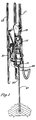
- Fig. 1 is a perspective view of a drilling apparatus of the invention;
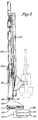
- Fig. 2 is a side view of a carriage and a wrench assembly; and
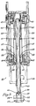
- Fig. 3 is a front view of a carriage and a wrench assembly.
- Figure 1 illustrates a top drive well drilling apparatus of the invention. A
conventional traveling block 13 and aconventional hook 15 are suspended by cables 17 from the top of an oil well derrick. Adrive unit 19 is suspended from thehook 15 and mounted on acarriage 21. Thedrive unit 19 is a drilling motor of a conventional type. Thecarriage 21 guides thedrive unit 19 up and down along a pair ofvertical guide tracks 23. A cylindrical quill, or stem 25, extends downward from thedrive unit 19, and connects to the top of adrill string 27. Thedrill string 27 consists of a series of pipe sections and has a rotary rock bit attached at the bottom for drilling a well bore. - A
wrench assembly 29 is provided for making up the connection between the stem 25 and thedrill string 27. The wrench assembly is mounted to thecarriage 21, and is capable of moving between a working position along the stem 25, or the axis of thedrill string 27, and a retracted position away from the axis of thedrill string 27. Thewrench assembly 29 is also capable of moving vertically along the stem 25 and thedrill string 27. - Figures 2 and 3 are close-up views of the
carriage 21 and thewrench assembly 29. Thewrench assembly 29 has atop wrench 33 and abottom wrench 35. Thesewrenches top wrench 33 is a spline wrench and is adapted to engage the step 25. Thebottom wrench 35 has grippers and is adapted to engage thedrill string 27. Thewrenches drill string 27 in a manner well known in the art. Thewrench assembly 29 can also be used to make up or break out connections between various subs between the stem 25 and thedrill string 27, such as kelly cocks. - The
wrench assembly 29 is carried by a C-shaped bracket 37. Thisbracket 37 has a T-shaped flange 39, which fits within aslot 41 on the bottom of a vertically movableinner tube 43. Thebracket 37 is also connected to ahydraulic cylinder 45, which is secured to aflange 47 extending down from theinner tube 43. - The
inner tube 43 passes upward between a set ofrollers 49 into anouter tube 51. Theinner tube 43 continues upward, out of theouter tube 51, and between a second set ofrollers 53. Thzouter tube 51 is welded to theframe 55 of thecarriage 21, and theinner tube 43 is movable vertically through theouter tube 51. - A pair of
chains 57 are attached tobrackets 59 on each side of theinner tube 43. Eachchain 57 extends upward, around apulley 61, and then downward to abracket 63 on thecarriage 21. Thebracket 37, theinner tube 43, and thechains 57 are thus a means for mounting the' wrench assembly 29 on thecarriage 21. Thepulleys 61 are each mounted on the lower ends ofhydraulic cylinders 65, the upper ends of which are connected to thecarriage 21. Thecarriage 21 has a plurality ofwheels 67, which guide thecarriage 21 along theguide track 23. - In operation, the
hydraulic cylinder 45 connected to thewrench assembly bracket 37 is a means for moving thewrench assembly 29 between a working position along the axis of thedrill string 27 and a retracted position away from the axis of thedrill string 27. Figure 2 illustrates thewrench assembly 29 in the working position, with thehydraulic cylinder 45 fully extended. As thecylinder 45 is retracted, thebracket 37 and thewrench assembly 29 are moved to the retracted position. When thecylinder 29 is extended, thebracket 37 andwrench assembly 29 are returned to the working position. - The
hydraulic cylinders 65 attached to thecarriage 21 are a means for moving thewrench assembly 29 vertically, relative to the stem 25. Figures 2 and 3 illustrate thewrench assembly 29 in the uppermost position relative to the stem 25, and thecylinders 65 are fully retracted. To lower thewrench assembly 29, thecylinders 65 are extended. Thechains 57 andpulleys 61 create a two to one ratio between the movement of thewrench assembly 29 and the movement of thepulleys 61. For example, if thecylinders 65 are extended to move thepulley 61 downward 1.22 m (four feet), thewrench assembly 29 will be moved downward a distance of 2.44 m (eight feet). - The well drilling apparatus of the invention has an improved
wrench assembly 29, which provides several advantages over the prior art. The capability of moving vertically enables the wrench assembly 29to break connections at several points along the stem 25 anddrill string 27, and the break out can be performed anywhere in the derrick. The retractability of thewrench assembly 29 enables thewrenches - While the invention has been shown in only one of its forms, it should be apparent to those skilled in the art that it is not so limited, but is susceptible to various changes and modifications, without departing from the scope thereof as defined by the appended claims.
Claims (2)
Applications Claiming Priority (2)
| Application Number | Priority Date | Filing Date | Title |
|---|---|---|---|
| US60093984A | 1984-04-16 | 1984-04-16 | |
| US600939 | 1984-04-16 |
Publications (2)
| Publication Number | Publication Date |
|---|---|
| EP0162001A1 EP0162001A1 (en) | 1985-11-21 |
| EP0162001B1 true EP0162001B1 (en) | 1989-08-30 |
Family
ID=24405689
Family Applications (1)
| Application Number | Title | Priority Date | Filing Date |
|---|---|---|---|
| EP19850630050 Expired EP0162001B1 (en) | 1984-04-16 | 1985-04-04 | Top drive well drilling apparatus with improved wrench assembly |
Country Status (4)
| Country | Link |
|---|---|
| EP (1) | EP0162001B1 (en) |
| CA (1) | CA1227189A (en) |
| DE (1) | DE3572709D1 (en) |
| NO (1) | NO165123C (en) |
Families Citing this family (2)
| Publication number | Priority date | Publication date | Assignee | Title |
|---|---|---|---|---|
| NO326329B1 (en) | 2006-06-19 | 2008-11-10 | Nat Oilwell Norway As | Lifting device |
| US11136837B2 (en) | 2017-01-18 | 2021-10-05 | Minex Crc Ltd | Mobile coiled tubing drilling apparatus |
Family Cites Families (5)
| Publication number | Priority date | Publication date | Assignee | Title |
|---|---|---|---|---|
| US3505913A (en) * | 1967-12-04 | 1970-04-14 | Byron Jackson Inc | Power tong crane |
| US3527309A (en) * | 1968-10-08 | 1970-09-08 | Central Mine Equipment Co | Vehicle-mounted earth drill with detachable tower |
| US3808916A (en) * | 1970-09-24 | 1974-05-07 | Robbins & Ass J | Earth drilling machine |
| US4345493A (en) * | 1980-10-22 | 1982-08-24 | Central Mine Equipment Company | Drill rod holding and break-out device |
| US4449596A (en) * | 1982-08-03 | 1984-05-22 | Varco International, Inc. | Drilling of wells with top drive unit |
-
1984
- 1984-12-18 CA CA000470375A patent/CA1227189A/en not_active Expired
-
1985
- 1985-04-04 DE DE8585630050T patent/DE3572709D1/en not_active Expired
- 1985-04-04 EP EP19850630050 patent/EP0162001B1/en not_active Expired
- 1985-04-15 NO NO851486A patent/NO165123C/en not_active IP Right Cessation
Also Published As
| Publication number | Publication date |
|---|---|
| NO165123B (en) | 1990-09-17 |
| CA1227189A (en) | 1987-09-22 |
| NO851486L (en) | 1985-10-17 |
| DE3572709D1 (en) | 1989-10-05 |
| NO165123C (en) | 1993-05-13 |
| EP0162001A1 (en) | 1985-11-21 |
Similar Documents
| Publication | Publication Date | Title |
|---|---|---|
| US4589503A (en) | Top drive drilling apparatus with improved wrench assembly | |
| US4667752A (en) | Top head drive well drilling apparatus with stabbing guide | |
| EP0093067B1 (en) | Beam type racking system | |
| US4348920A (en) | Well pipe connecting and disconnecting apparatus | |
| CA2189376C (en) | Hybrid coiled tubing/conventional drilling unit | |
| US5735351A (en) | Top entry apparatus and method for a drilling assembly | |
| US7637329B2 (en) | Methods and systems for drilling auxiliary holes | |
| IE42448B1 (en) | A power swivel assembly for a drilling rig | |
| GB1515974A (en) | Rotary drilling rig | |
| EP0162000A1 (en) | Top drive well drilling apparatus with removable link adapter | |
| US11060361B2 (en) | Retractable top drive with torque tube | |
| US4671365A (en) | Drill feeding and hoisting system for an earthdrill | |
| US2730246A (en) | Apparatus for handling pipe in a derrick | |
| EP0162001B1 (en) | Top drive well drilling apparatus with improved wrench assembly | |
| US4250973A (en) | Rock drilling apparatus | |
| WO1996005402A1 (en) | Direction controllable subsurface borehole tool | |
| US11708723B2 (en) | Guide for top drive unit | |
| CN109594919A (en) | A kind of foldable tunnel frame pipe machine of coal mine track walking | |
| GB2163372A (en) | Boring carriage | |
| US4503917A (en) | Carriage feed system | |
| EP0166675B1 (en) | Wrench and wrench assembly | |
| CN111980599A (en) | Lifting type ground pulley device for steel wire operation | |
| US3376938A (en) | Adjustable drilling mast having spaced swivel and traveling block guides | |
| GB2178780A (en) | Side drive drilling | |
| US4539893A (en) | Power feed system for a rotary drill |
Legal Events
| Date | Code | Title | Description |
|---|---|---|---|
| PUAI | Public reference made under article 153(3) epc to a published international application that has entered the european phase |
Free format text: ORIGINAL CODE: 0009012 |
|
| AK | Designated contracting states |
Designated state(s): DE FR GB |
|
| 17P | Request for examination filed |
Effective date: 19860206 |
|
| 17Q | First examination report despatched |
Effective date: 19870803 |
|
| GRAA | (expected) grant |
Free format text: ORIGINAL CODE: 0009210 |
|
| RAP1 | Party data changed (applicant data changed or rights of an application transferred) |
Owner name: VARCO INTERNATIONAL, INC. |
|
| AK | Designated contracting states |
Kind code of ref document: B1 Designated state(s): DE FR GB |
|
| RAP2 | Party data changed (patent owner data changed or rights of a patent transferred) |
Owner name: VARCO INTERNATIONAL, INC. |
|
| REF | Corresponds to: |
Ref document number: 3572709 Country of ref document: DE Date of ref document: 19891005 |
|
| ET | Fr: translation filed | ||
| PLBI | Opposition filed |
Free format text: ORIGINAL CODE: 0009260 |
|
| 26 | Opposition filed |
Opponent name: ATELIERS ET CHANTIERS DE BRETAGNE ACB Effective date: 19900529 |
|
| PLBN | Opposition rejected |
Free format text: ORIGINAL CODE: 0009273 |
|
| STAA | Information on the status of an ep patent application or granted ep patent |
Free format text: STATUS: OPPOSITION REJECTED |
|
| 27O | Opposition rejected |
Effective date: 19930131 |
|
| REG | Reference to a national code |
Ref country code: GB Ref legal event code: IF02 |
|
| PGFP | Annual fee paid to national office [announced via postgrant information from national office to epo] |
Ref country code: GB Payment date: 20040331 Year of fee payment: 20 |
|
| PGFP | Annual fee paid to national office [announced via postgrant information from national office to epo] |
Ref country code: DE Payment date: 20040408 Year of fee payment: 20 |
|
| PGFP | Annual fee paid to national office [announced via postgrant information from national office to epo] |
Ref country code: FR Payment date: 20040415 Year of fee payment: 20 |
|
| PG25 | Lapsed in a contracting state [announced via postgrant information from national office to epo] |
Ref country code: GB Free format text: LAPSE BECAUSE OF EXPIRATION OF PROTECTION Effective date: 20050403 |
|
| REG | Reference to a national code |
Ref country code: GB Ref legal event code: PE20 |
|
| APAH | Appeal reference modified |
Free format text: ORIGINAL CODE: EPIDOSCREFNO |