EP0161990B1 - Abtastanordnung eines Organes in einer Fläche senkrecht zu seiner Fortbewegungsrichtung - Google Patents
Abtastanordnung eines Organes in einer Fläche senkrecht zu seiner Fortbewegungsrichtung Download PDFInfo
- Publication number
- EP0161990B1 EP0161990B1 EP85400914A EP85400914A EP0161990B1 EP 0161990 B1 EP0161990 B1 EP 0161990B1 EP 85400914 A EP85400914 A EP 85400914A EP 85400914 A EP85400914 A EP 85400914A EP 0161990 B1 EP0161990 B1 EP 0161990B1
- Authority
- EP
- European Patent Office
- Prior art keywords
- signal
- displacement
- regulating
- speed
- movement
- Prior art date
- Legal status (The legal status is an assumption and is not a legal conclusion. Google has not performed a legal analysis and makes no representation as to the accuracy of the status listed.)
- Expired
Links
- 238000006073 displacement reaction Methods 0.000 claims description 34
- 230000001360 synchronised effect Effects 0.000 claims description 6
- 230000001105 regulatory effect Effects 0.000 claims 15
- 230000001276 controlling effect Effects 0.000 claims 2
- 230000000694 effects Effects 0.000 claims 1
- 235000010599 Verbascum thapsus Nutrition 0.000 description 75
- 238000003466 welding Methods 0.000 description 47
- 238000010586 diagram Methods 0.000 description 10
- 230000010355 oscillation Effects 0.000 description 10
- 238000010408 sweeping Methods 0.000 description 10
- 244000178289 Verbascum thapsus Species 0.000 description 6
- 230000004048 modification Effects 0.000 description 5
- 238000012986 modification Methods 0.000 description 5
- 238000000034 method Methods 0.000 description 4
- 210000000056 organ Anatomy 0.000 description 3
- 230000001052 transient effect Effects 0.000 description 3
- 239000011324 bead Substances 0.000 description 2
- 230000000903 blocking effect Effects 0.000 description 2
- 238000005520 cutting process Methods 0.000 description 2
- 238000004026 adhesive bonding Methods 0.000 description 1
- 239000003990 capacitor Substances 0.000 description 1
- 230000003247 decreasing effect Effects 0.000 description 1
- 230000001066 destructive effect Effects 0.000 description 1
- 238000000227 grinding Methods 0.000 description 1
- 238000003754 machining Methods 0.000 description 1
- 239000002184 metal Substances 0.000 description 1
- 230000000630 rising effect Effects 0.000 description 1
- 239000000523 sample Substances 0.000 description 1
- 230000001960 triggered effect Effects 0.000 description 1
Images
Classifications
-
- B—PERFORMING OPERATIONS; TRANSPORTING
- B23—MACHINE TOOLS; METAL-WORKING NOT OTHERWISE PROVIDED FOR
- B23K—SOLDERING OR UNSOLDERING; WELDING; CLADDING OR PLATING BY SOLDERING OR WELDING; CUTTING BY APPLYING HEAT LOCALLY, e.g. FLAME CUTTING; WORKING BY LASER BEAM
- B23K9/00—Arc welding or cutting
- B23K9/02—Seam welding; Backing means; Inserts
- B23K9/0216—Seam profiling, e.g. weaving, multilayer
Definitions
- the present invention relates to a device for scanning an organ in a plane perpendicular to its direction of advance and applies in particular to the scanning of a welding torch in two directions contained in a scanning plane perpendicular to its direction in advance to fill a joint between two parts with a weld bead.
- the invention is not limited to the scanning of a welding torch but also applies, for example, to the scanning of a non-destructive control sensor, of a cutting, machining, grinding, gluing or others.
- the sweeping movement of a welding torch is necessary for filling the corner joints or large chamfers. This sweeping movement is carried out in a plane perpendicular to the advance of the welding torch along this joint. It is generally used for processes with good filling power such as MIG, MAG and cored wire processes.
- the scanning movement is limited to a scanning direction along which the welding torch has an oscillating movement.
- This scanning direction contained in the plane perpendicular to the advance of the torch, is often parallel to the external bisector of the welding joint.
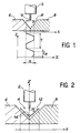
- FIG. 1 a schematic drawing illustrating the scanning movement of the torch in known devices.
- the welding torch 2 is presented in line with a joint 4 defined by the juxtaposition of two chamfered parts 6 and 8. These parts are shown in section in a plane transverse to the direction of the joint.
- the movement of the welding torch 2 has been indicated by an arrow referenced 10 in this cutting plane.
- the curve of the position x of the end of the welding torch 2 on the scanning axis X as a function of time t is completely determined by the amplitude a of its oscillation, the duration t e of the time delay at the ends and the scanning speed.
- the object of the invention is to remedy this: it is sought, for filling the corner joints and large chamfers, to generate a two-dimensional sweeping movement in the transverse plane in advance of the welding torch .
- the invention specifically relates to a scanning device which simply generates displacements in each of the two scanning directions.
- the invention relates to a device for scanning an organ in a plane perpendicular to its direction of advance, comprising a first means of displacement of the organ in a first direction contained in the plane of scanning, a second means of displacement of the member in a second direction contained in the scanning plane, a speed control means connected to the first displacement means and defining the law of movement in the first direction, a control means in position connected to the second displacement means and defining the law of movement in the second direction, said position control means receiving a position signal delivered by a position encoder associated with the displacement means in the first direction and said control means being synchronized by a signal which is a function of the result of the comparison between the amplitude of said position signal and a reference amplitude.
- the scanning directions are perpendicular to each other and to the direction of advance.
- these are preferably the external bisector of the joint and the internal bisector of the joint.
- adjustment means are provided for determining the law of movement in each direction.
- the adjustment means associated with the speed control means comprise a means for adjusting the speed by the amplitude of the speed control signal, a means for adjusting the delay time by the duration of a pulse triggered by a synchronization signal and a means for adjusting the amplitude of the displacement in the first scanning direction.
- the adjustment means associated with the position control means comprise a means for adjusting the slope of the joint, by a gain applied to the position signal in the first direction, a means for adjusting the rounding by signal offset and rectification and a decimal means lage in the second scanning direction by a new signal offset.
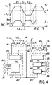
- FIG. 2 illustrates a scanning movement of the welding torch 2 produced by the scanning device according to the invention.
- the sweeping movement is obtained by the combination of two oscillating movements in two perpendicular directions X and Z, which, in this example, are respectively parallel to the external bisector of the joint 4 defined by the juxtaposition of the two parts 6 and 8, and to the interior bisector of this same joint.
- Other directions can be chosen. These directions are preferably perpendicular to each other.
- the location of the welding torch 2 in this scanning plane is represented by the curve 12.
- the curve 12 does not does not represent the scanning movement of the torch in a fixed plane but the projection of this movement in a fixed plane.
- the curve 12 is preferably parallel to the sides of the joint. It can have a rounded in its lower part, that is to say at the center of the travel of the torch along the X axis, allowing the adjustment of the quantity of metal deposited.
- rounding it should be understood that the angle formed by the trajectory of the torch above the joint is suppressed when it moves, in the direction X, at constant altitude above the flanks of the attached. A simple way of making this round consists in blocking the position of the torch along the Z axis. The torch then describes the curve segment referenced 14.
- FIGS. 3a and 3b show timing diagrams representing these synchronized oscillation movements.
- the movement along the X axis is defined by three parameters: the amplitude x M of the movement, the speed v ,, of the movement which is linked to the duration t, to move the welding torch from the position -x M to the position + x M , and the duration t z of delay when the torch is in the position + x M.
- the amplitude x M of the movement the speed v , the movement which is linked to the duration t, to move the welding torch from the position -x M to the position + x M
- the duration t z of delay when the torch is in the position + x M During this time t 2 , there is no sweeping movement.
- the torch is blocked in the X and Z directions, but the torch can move in the direction of advance perpendicular to the scanning plane.
- FIG. 3b shows the shape of the oscillation movement of the welding torch along the Z axis This movement is defined by the minimum amplitudes z m and maximum z M of the torch.
- the duration of the torch delay in the positions (x M , z M ) and (-x M , z M ) is equal to t z .
- the duration t 3 of the torch blocking along the Z axis is linked to the value z a which defines the rounding and to the speed v z of displacement of the torch along the Z axis which is itself a function of the speed v x of displacement along the axis X and of the slope a of the joint.
- This device comprises a first displacement means 16 for generating a movement of the welding torch along the X axis, a second displacement means 18 for generating a movement of the welding torch along the Z axis, a control means 20 of the first displacement means 16, a control means 22 of the second displacement means 18, a position encoder 24 along the X axis delivering a reference signal to the control means 20 and a position encoder 26 along the Z axis issuing a setpoint signal by means of com mande 22.
- the device finally comprises adjustment means 28, 30, 32, 34, 36 and 38 making it possible to define the laws of movement along each of the scanning axes.
- Synchronization of the control means 20 and 22 is achieved by a pulse signal delivered by a comparator receiving the signal from the position encoder 24 and the signal delivered by the adjustment means 28, and detecting the equality of these signals, the change of state of the comparator controlling the state (blocked, unlocked) of the welding torch in each scanning direction.
- Each displacement means 16, 18 comprises an amplifier 16a, 18a and a motor 16b, 18b.
- the rotation of the motor 16b is controlled in speed in a conventional manner, each operating phase of speed, direction and duration determined corresponding to a pulse of amplitude, sign and duration determined.
- control means 20 for displacement along the X axis delivers a speed control signal to the displacement means 16.
- This control means comprises a processing means 21 and a speed control means 23.
- the processing means 21 receives the position signal x delivered by the position encoder 24 and signals delivered by the adjustment means 28, 32, and 30 respectively fixing the amplitude x M of the movement along the X axis, the speed of this movement and the duration t 2 of the time delay in the positions of maximum amplitudes + x M. It delivers a speed control signal v x by means of speed control 23.
- the latter controls the speed of the motor of the first displacement means 16 so as to make the control speed v x and the variation dx / dt of the signal identical.
- This means 23 is not compulsory but can be useful in the case of control at low speed.
- the second control means 22 performs a control in position of the welding torch along the Z axis.
- This control means comprises in series an amplifier and rectifier means 40, a processing means 42 and a servo means in position 44 .
- the amplifier and rectifier means 40 receives the position signal x delivered by the position encoder 24 and a signal indicating the slope a of the joint determined by the adjusting means 34. It delivers a signal z l .
- This signal is received by the processing means 42 which also receives offset signals delivered by the adjustment means 36 and 38. These adjustment means respectively determine the rounding and an offset along the axis Z of the trajectory of the torch.
- the position signal z delivered by this processing means is received by the servo means in position 44. The latter controls by a connection 46 the motor of the second displacement means 18 in order to make the desired position of the torch defined by the signal z and the actual position of the torch indicated by the position encoder 26.
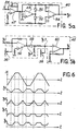
- FIGS. 5a and 5b respectively represent an embodiment of the amplifier and rectifier means 40 and of the processing means 42 of the control means 22 .
- the amplifier and rectifier means 40 shown in FIG. 5a delivers a signal Z1 as a function of the position signal x delivered by the position sensor along the axis X.
- the amplifier stage includes an amplifier stage and a rectifier stage.
- the amplifier stage consists of a differential amplifier 47 mounted as a negative gain voltage amplifier with an adjustable feedback resistance which constitutes the adjustment means 34.
- the signal x 1 delivered by the amplifier stage is then rectified by the rectifier stage.
- These signals are applied respectively to the inverting and non-inverting inputs of a differential amplifier 54 which delivers a signal z 1 equal to the rectified signal X1 .
- the signal z i is represented in correspondence with the signal x in Figure 6.
- the ratio of the amplitudes of these signals, and therefore the ratio of the slopes of these signals, is related to the angle a of the joint ( Figure 2). This relationship is fixed by the adjusting means 34.
- FIG. 5b represents an embodiment of the means 42 for processing the position signal z from the signal z i .
- the signal z i is first received in a circuit comprising a differential amplifier 56 mounted as a voltage inverter and the means for adjusting the rounding 36. This assembly performs an offset and then an inversion of the signal z 1 .
- the signal produced, denoted z 2 is shown in FIG. 6. This signal is applied to the anode of a diode 58, which clips its positive part.
- the resulting signal z 3 is represented in FIG. 6.
- This signal is treated in the same way as the signal z i , that is to say that it is received in an assembly comprising a shift means 38 and an amplifier differential 60 mounted as a voltage reverser.
- the signal z obtained represents the command in position of the welding torch in the scanning direction Z over time.
- This control signal z is received in the position control means 44 (FIG. 4) which conventionally controls the motor of the movement means 18 so that the position encoder 26 in the direction Z indicates a position of the welding torch according to a position setpoint.
- the displacement along the other scanning direction X is produced by a speed control.
- the processing means of the control means along this axis receives as input the position x of the torch along the axis X and outputs a speed control signal v ,, of the torch along this axis.
- This voltage signal is in the form of a succession of positive, zero and negative slots, sequentially switched by time pulses generated when the torch reaches two extreme positions x M and -x M , along the X axis.
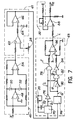
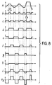
- FIG 7 an embodiment of this processing means and in Figure 8 a timing diagram of the main signals of this processing means.
- the position signal x received by the processing means is first rectified by means 41 identical to the rectifier stage of the means 40 in FIG. 5a. This rectified signal is then received on the non-inverting input of a comparator 62, part of a digitizing means 61. On its inverting input, the comparator 62 receives a reference signal defined by the adjusting means 28 which thus defines the amplitude x M of the movement along the X axis.
- the two-state signal delivered by the comparator 62 is then processed by an assembly comprising a Zener diode 64 and an amplifier 66 whose output is looped back to the inverting input. This assembly transforms the signal delivered by the comparator 62 into a logic signal (of TTL level if the Zener diode has a clipping voltage of 4.7 V) which allows its processing by logic means.
- This logic signal delivered by the means 61 is therefore in the high state when the absolute value of the abscissa of the welding torch is greater than or equal to x M and in the low state otherwise.
- This signal is processed by a means 68 which delivers voltage slots controlling the size and sign of the speed of movement of the welding torch along the X axis.
- the signal delivered by the means 61 is received in a monostable circuit 70 whose period is fixed by a capacitor 72 and an adjustable resistance constituting the adjustment means 30.
- the signal b delivered by the monostable circuit 70 is shown in FIG. 8.
- the adjustment means 30 which determines the duration of the pulses of the signal b makes it possible to fix the duration of the time delay of the welding torch in the positions of maximum amplitude along the axis X.
- the logic signal delivered by the means 61 is applied on the other hand to the input of a flip-flop 74 which delivers a signal d shown in FIG. 8.
- This signal d is received on an input of an AND gate 78 whose the other input receives the signal c obtained by inversion of the signal b in a logic inverter 76.
- Another AND gate 82 receives as input the signal c and the signal e obtained by inversion of the signal d in a logic inverter 80.
- the signals f and g produced by these AND gates 78 and 82 are represented in FIG. 8. These are signals in slots which are in the high state when the welding torch has a negative and positive speed respectively along the X axis. .
- the circuit 68 finally comprises a summator consisting of a differential amplifier 86 receiving on its inverting input the signal f and on its non-inverting input the signal h obtained by inverting the signal g in a logic inverter 84.
- the signal i produced by this circuit 68 is shown in FIG. 8. It is a bipolar signal in a slot indicating the sign of the speed along the X axis. The speed of movement along the X axis is constant and of the same sign as this signal i.
- This signal is finally received in a differential amplifier 88, the gain of which can be adjusted by an adjustable resistor constituting the adjustment means 32.
- the signal v x delivered is proportional to the signal i and its amplitude, fixed by the adjustment means 32, defines the speed of the torch along the X axis.
- the position signal x of the welding torch shown in FIG. 8 corresponds to three oscillations. During the first two oscillations, the signals delivered by the adjustment means are constant.
- the third oscillation is different because the speed, the amplitude of the movement and the delay time of the movement of the probe have been modified by acting on the adjustment means 32, 28 and 30.
- the change in speed appears on the signal v x where the last two pulses have a greater amplitude than the previous pulses.
- the modification of the amplitude of the movement results in a rising edge of the pulse of signal b at date t 4 for a amplitude of signal x greater than for the previous pulses of signal b.
- the circuits described with reference to FIGS. 5a, 5b and 7 are therefore able to control the oscillating movements of the welding torch in two directions, which generates the scanning movement. Adjustment means associated with these control means make it possible to independently vary each parameter of the laws of oscillation movements.
- the scanning device is started automatically on power up.
- a transient movement of the torch may occur before the nominal sweeping movement. Whatever the sign of the engine launch voltage window, this transient movement will bring the torch back to a normal position.
- This transient movement takes place if, when the engine is started, the position encoder along the X axis indicates an amplitude greater (respectively less) than the maximum amplitude x M (respectively minimum -x M ) defined by the adjusting means 28 .
- the comparator 62 detects that the position has been exceeded and generates a impulse (signal b) which itself creates a speed slot. If this speed slot produces a movement which increases the amplitude of the welding torch, the comparator 62 again generates a pulse (signal b) which creates a speed slot of opposite sign.
- the welding torch then has a movement bringing it back into the range [-x M , + XM] ; the movement of the torch is then the normal sweeping movement. If the first speed slot returns the torch to the range [- XM , + x M] , normal scanning operation occurs without a new pulse from the comparator.
- FIGs 4 to 8 which have just been described illustrate a device for the implementation of the scanning movement shown in Figures 3a and 3b and the operation of this device.
- the scanning movement described is only an example of a scanning movement which can be produced in accordance with the invention. We will successively describe two variants of this scanning movement and we will indicate the modifications made to the device of FIG. 4 for the implementation of these variants.
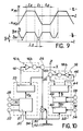
- FIGS. 9a and 9b illustrate a first variant in which the sweeping movement is no longer centered on the axis of the joint but offset in the direction X.
- the references identical to those of the chronograms of FIGS. 3a and 3b have the same meaning.
- the movement in the direction X is between the amplitudes X M1 and -X M2 . These are not identical.
- FIGS. 9a and 9b The scanning movement shown in FIGS. 9a and 9b is implemented by the device in FIG. 10. This is practically identical to the device described with reference to FIG. 4. It differs from it only by the addition of a adder 90 which receives on the one hand the signal delivered by the position encoder 24 and on the other hand an offset signal produced by a potentiometer 92.
- the signal delivered by the adder 90 constitutes the reference signal applied to the control means 20 and 22.
- the summing assembly 90 and potentiometer 92 constitutes a means 94 for adjusting the offset in the first direction X.
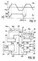
- FIGS. 11 a and 11 b Another variant of the sweeping movement of the welding torch is shown in FIGS. 11 a and 11 b.
- the movement of the torch is blocked in the direction Z when it moves in a particular direction, here the decreasing direction, in the first direction X.
- a device such as that of FIG. 4 is used in which means 96 have been added receiving the position signal delivered by the position encoder 24 and delivering a signal to the processing means 42.
- a switch has been placed behind the diode 58 (FIG. 5b) to apply to the differential amplifier 60 either the signal z 3 , or a zero signal.
- This switch is controlled by a relay activated by the signal delivered by the means 96.
- the latter comprises a tap-off followed by a sign detector.
- the means 96 controls the switch to connect the input of the differential amplifier 60 to ground; when the sign of the derived signal is positive or zero, the means 96 controls the switch to apply the signal z 3 to the differential amplifier 60.
Landscapes
- Engineering & Computer Science (AREA)
- Physics & Mathematics (AREA)
- Plasma & Fusion (AREA)
- Mechanical Engineering (AREA)
- Butt Welding And Welding Of Specific Article (AREA)
Claims (12)
Applications Claiming Priority (2)
| Application Number | Priority Date | Filing Date | Title |
|---|---|---|---|
| FR8407493 | 1984-05-15 | ||
| FR8407493A FR2564359B1 (fr) | 1984-05-15 | 1984-05-15 | Dispositif de balayage d'un organe dans un plan perpendiculaire a sa direction d'avance |
Publications (2)
| Publication Number | Publication Date |
|---|---|
| EP0161990A1 EP0161990A1 (de) | 1985-11-21 |
| EP0161990B1 true EP0161990B1 (de) | 1989-02-08 |
Family
ID=9303984
Family Applications (1)
| Application Number | Title | Priority Date | Filing Date |
|---|---|---|---|
| EP85400914A Expired EP0161990B1 (de) | 1984-05-15 | 1985-05-10 | Abtastanordnung eines Organes in einer Fläche senkrecht zu seiner Fortbewegungsrichtung |
Country Status (4)
| Country | Link |
|---|---|
| US (1) | US4689469A (de) |
| EP (1) | EP0161990B1 (de) |
| DE (1) | DE3568147D1 (de) |
| FR (1) | FR2564359B1 (de) |
Families Citing this family (6)
| Publication number | Priority date | Publication date | Assignee | Title |
|---|---|---|---|---|
| US5552575A (en) * | 1994-07-15 | 1996-09-03 | Tufts University | Scan welding method and apparatus |
| US6966908B2 (en) | 1997-07-08 | 2005-11-22 | Atrionix, Inc. | Tissue ablation device assembly and method for electrically isolating a pulmonary vein ostium from an atrial wall |
| US6064168A (en) * | 1998-03-13 | 2000-05-16 | Fanuc Robotics North America, Inc. | Method of controlling robot movement |
| US6436345B1 (en) * | 2001-03-23 | 2002-08-20 | Chemtreat, Inc. | Method for generating chlorine dioxide |
| US20130119032A1 (en) * | 2011-11-11 | 2013-05-16 | Lincoln Global, Inc. | System and method for welding materials of different conductivity |
| WO2016005882A1 (en) | 2014-07-07 | 2016-01-14 | Victoria Link Ltd | Method and apparatus for cryogenic cooling of hts devices immersed in liquid cryogen |
Family Cites Families (5)
| Publication number | Priority date | Publication date | Assignee | Title |
|---|---|---|---|---|
| JPS5820705B2 (ja) * | 1974-12-11 | 1983-04-25 | オオサカヘンアツキ カブシキガイシヤ | ア−ク溶接装置 |
| SE401637B (sv) * | 1976-03-29 | 1978-05-22 | Asea Ab | Forfarande och anordning for att bringa en industrirobot att utfora en komplex rorelse |
| US4316075A (en) * | 1980-04-08 | 1982-02-16 | Kabushiki Kaisha Komatsu Seisakusho | Automatic welding position control method, and device |
| JPS57109575A (en) * | 1980-12-27 | 1982-07-08 | Nippon Kokan Kk <Nkk> | Arc welding method |
| US4434352A (en) * | 1982-05-05 | 1984-02-28 | Nippon Kokan Kabushiki Kaisha | Arc welding method for automatically reversing a welding torch in the width direction of the groove at a set position |
-
1984
- 1984-05-15 FR FR8407493A patent/FR2564359B1/fr not_active Expired
-
1985
- 1985-05-08 US US06/731,972 patent/US4689469A/en not_active Expired - Fee Related
- 1985-05-10 EP EP85400914A patent/EP0161990B1/de not_active Expired
- 1985-05-10 DE DE8585400914T patent/DE3568147D1/de not_active Expired
Also Published As
| Publication number | Publication date |
|---|---|
| EP0161990A1 (de) | 1985-11-21 |
| US4689469A (en) | 1987-08-25 |
| FR2564359B1 (fr) | 1988-06-10 |
| FR2564359A1 (fr) | 1985-11-22 |
| DE3568147D1 (en) | 1989-03-16 |
Similar Documents
| Publication | Publication Date | Title |
|---|---|---|
| FR2489545A1 (fr) | Systeme adaptif pour la detection des defaillances d'une servocommande d'un aeronef | |
| EP0835802B1 (de) | Steuerungshilfevorrichtung für ein Flugzeug mit einem elektrischen Flugsteuerungssystem | |
| EP0161990B1 (de) | Abtastanordnung eines Organes in einer Fläche senkrecht zu seiner Fortbewegungsrichtung | |
| FR2569879A1 (fr) | Dispositif de controle et procede de detection acoustique d'un contact entre un outil de coupe et une piece | |
| EP3804920B1 (de) | Kollaborative vorrichtung mit optimierter steuerung | |
| EP0834787B1 (de) | Methode und Vorrichtung zur vertikalen Führung eines Flugzeugs | |
| EP0065901B1 (de) | Potentiometermesswertumformersystem | |
| EP0064454B1 (de) | Verfahren zum lateralen Positionieren eines Gliedes bezüglich einer zwischen zwei metallischen Oberflächen formierten und mit Unterbrechungen versehenen Fuge | |
| FR2474716A1 (fr) | Appareil de stabilisation et de reglage automatique pour aeronef | |
| FR2671305A1 (fr) | Procede de pilotage d'un bras de robot en definissant des trajets de substitution. | |
| EP0796439A1 (de) | Empfangsverfahren mit mehrdeutigkeitsentfernung für akustische lineare schleppantenne | |
| EP1310768B1 (de) | Verfahren und Vorrichtung zur Anzeige des Geschwindigkeitsvektors eines Flugzeugs | |
| EP0115728B1 (de) | Ausrichtbarer Geräteträger für Roboter | |
| EP0036374B1 (de) | Verfahren und Vorrichtung zum Schweissen mit automatischem Folgen der Schweissnaht | |
| EP0816795A2 (de) | Länge- oder Winkelmessinstrument | |
| FR2807711A1 (fr) | Dispositif et procede de marquage | |
| FR2616533A1 (fr) | Systeme de localisation d'un objet dans l'espace | |
| WO2023006997A1 (fr) | Balai d'essuyage avec élément de projection d'un fluide de nettoyage | |
| FR2757467A1 (fr) | Systeme de commande du fonctionnement d'un mecanisme d'essuie-vitre d'un vehicule automobile | |
| EP0647169B1 (de) | Verfahren und vorrichtung insbesondere zur kontaktlosen kontrolle, um eine werkzeuganlage in einer relativen konstanten lage im vergleich mit einer nicht planen ebene zu halten | |
| FR2544097A1 (fr) | Robot industriel avec dispositifs d'entrainement pour des mouvements a au moins un degre de liberte | |
| EP3543077B1 (de) | Kontrollverfahren eines scheibenreinigungssystems eines kraftfahrzeugs | |
| EP1586858B1 (de) | Verfahren zum Gegentaktantrieb eines Laserkreisels | |
| FR2498513A1 (fr) | Dispositif pour corriger les flexions du couteau d'une machine automatique de coupe | |
| FR3126112A1 (fr) | Balai d’essuyage avec élément de projection d’un fluide de nettoyage |
Legal Events
| Date | Code | Title | Description |
|---|---|---|---|
| PUAI | Public reference made under article 153(3) epc to a published international application that has entered the european phase |
Free format text: ORIGINAL CODE: 0009012 |
|
| AK | Designated contracting states |
Designated state(s): BE DE GB IT SE |
|
| 17P | Request for examination filed |
Effective date: 19860416 |
|
| 17Q | First examination report despatched |
Effective date: 19870212 |
|
| RAP1 | Party data changed (applicant data changed or rights of an application transferred) |
Owner name: COMMISSARIAT A L'ENERGIE ATOMIQUE |
|
| GRAA | (expected) grant |
Free format text: ORIGINAL CODE: 0009210 |
|
| AK | Designated contracting states |
Kind code of ref document: B1 Designated state(s): BE DE GB IT SE |
|
| REF | Corresponds to: |
Ref document number: 3568147 Country of ref document: DE Date of ref document: 19890316 |
|
| ITF | It: translation for a ep patent filed | ||
| PGFP | Annual fee paid to national office [announced via postgrant information from national office to epo] |
Ref country code: SE Payment date: 19890425 Year of fee payment: 5 |
|
| PGFP | Annual fee paid to national office [announced via postgrant information from national office to epo] |
Ref country code: DE Payment date: 19890429 Year of fee payment: 5 |
|
| PGFP | Annual fee paid to national office [announced via postgrant information from national office to epo] |
Ref country code: BE Payment date: 19890502 Year of fee payment: 5 |
|
| GBT | Gb: translation of ep patent filed (gb section 77(6)(a)/1977) | ||
| ITTA | It: last paid annual fee | ||
| PGFP | Annual fee paid to national office [announced via postgrant information from national office to epo] |
Ref country code: GB Payment date: 19890531 Year of fee payment: 5 |
|
| PLBE | No opposition filed within time limit |
Free format text: ORIGINAL CODE: 0009261 |
|
| STAA | Information on the status of an ep patent application or granted ep patent |
Free format text: STATUS: NO OPPOSITION FILED WITHIN TIME LIMIT |
|
| 26N | No opposition filed | ||
| PG25 | Lapsed in a contracting state [announced via postgrant information from national office to epo] |
Ref country code: GB Effective date: 19900510 |
|
| PG25 | Lapsed in a contracting state [announced via postgrant information from national office to epo] |
Ref country code: SE Effective date: 19900511 |
|
| PG25 | Lapsed in a contracting state [announced via postgrant information from national office to epo] |
Ref country code: BE Effective date: 19900531 |
|
| BERE | Be: lapsed |
Owner name: COMMISSARIAT A L'ENERGIE ATOMIQUE Effective date: 19900531 |
|
| GBPC | Gb: european patent ceased through non-payment of renewal fee | ||
| PG25 | Lapsed in a contracting state [announced via postgrant information from national office to epo] |
Ref country code: DE Effective date: 19910201 |
|
| EUG | Se: european patent has lapsed |
Ref document number: 85400914.9 Effective date: 19910115 |