EP0161972A2 - Hydraulische Schere - Google Patents
Hydraulische Schere Download PDFInfo
- Publication number
- EP0161972A2 EP0161972A2 EP85400780A EP85400780A EP0161972A2 EP 0161972 A2 EP0161972 A2 EP 0161972A2 EP 85400780 A EP85400780 A EP 85400780A EP 85400780 A EP85400780 A EP 85400780A EP 0161972 A2 EP0161972 A2 EP 0161972A2
- Authority
- EP
- European Patent Office
- Prior art keywords
- blade
- deck
- movable
- box
- horizontal
- Prior art date
- Legal status (The legal status is an assumption and is not a legal conclusion. Google has not performed a legal analysis and makes no representation as to the accuracy of the status listed.)
- Withdrawn
Links
- 230000000694 effects Effects 0.000 claims abstract description 10
- 238000005452 bending Methods 0.000 claims abstract description 9
- 229910000831 Steel Inorganic materials 0.000 abstract description 2
- 239000010959 steel Substances 0.000 abstract description 2
- 238000006243 chemical reaction Methods 0.000 description 10
- 238000010586 diagram Methods 0.000 description 5
- 238000010008 shearing Methods 0.000 description 3
- 241001080024 Telles Species 0.000 description 2
- 230000007423 decrease Effects 0.000 description 2
- 238000005192 partition Methods 0.000 description 2
- 239000011324 bead Substances 0.000 description 1
- 230000001186 cumulative effect Effects 0.000 description 1
- 238000006073 displacement reaction Methods 0.000 description 1
- 238000012423 maintenance Methods 0.000 description 1
- 238000004519 manufacturing process Methods 0.000 description 1
- 238000003466 welding Methods 0.000 description 1
Images


Classifications
-
- B—PERFORMING OPERATIONS; TRANSPORTING
- B23—MACHINE TOOLS; METAL-WORKING NOT OTHERWISE PROVIDED FOR
- B23D—PLANING; SLOTTING; SHEARING; BROACHING; SAWING; FILING; SCRAPING; LIKE OPERATIONS FOR WORKING METAL BY REMOVING MATERIAL, NOT OTHERWISE PROVIDED FOR
- B23D15/00—Shearing machines or shearing devices cutting by blades which move parallel to themselves
- B23D15/12—Shearing machines or shearing devices cutting by blades which move parallel to themselves characterised by drives or gearings therefor
- B23D15/14—Shearing machines or shearing devices cutting by blades which move parallel to themselves characterised by drives or gearings therefor actuated by fluid or gas pressure
-
- B—PERFORMING OPERATIONS; TRANSPORTING
- B23—MACHINE TOOLS; METAL-WORKING NOT OTHERWISE PROVIDED FOR
- B23D—PLANING; SLOTTING; SHEARING; BROACHING; SAWING; FILING; SCRAPING; LIKE OPERATIONS FOR WORKING METAL BY REMOVING MATERIAL, NOT OTHERWISE PROVIDED FOR
- B23D35/00—Tools for shearing machines or shearing devices; Holders or chucks for shearing tools
- B23D35/005—Adjusting the position of the cutting members
-
- Y—GENERAL TAGGING OF NEW TECHNOLOGICAL DEVELOPMENTS; GENERAL TAGGING OF CROSS-SECTIONAL TECHNOLOGIES SPANNING OVER SEVERAL SECTIONS OF THE IPC; TECHNICAL SUBJECTS COVERED BY FORMER USPC CROSS-REFERENCE ART COLLECTIONS [XRACs] AND DIGESTS
- Y10—TECHNICAL SUBJECTS COVERED BY FORMER USPC
- Y10T—TECHNICAL SUBJECTS COVERED BY FORMER US CLASSIFICATION
- Y10T83/00—Cutting
- Y10T83/869—Means to drive or to guide tool
- Y10T83/8717—By deforming resilient tool or tool support
-
- Y—GENERAL TAGGING OF NEW TECHNOLOGICAL DEVELOPMENTS; GENERAL TAGGING OF CROSS-SECTIONAL TECHNOLOGIES SPANNING OVER SEVERAL SECTIONS OF THE IPC; TECHNICAL SUBJECTS COVERED BY FORMER USPC CROSS-REFERENCE ART COLLECTIONS [XRACs] AND DIGESTS
- Y10—TECHNICAL SUBJECTS COVERED BY FORMER USPC
- Y10T—TECHNICAL SUBJECTS COVERED BY FORMER US CLASSIFICATION
- Y10T83/00—Cutting
- Y10T83/869—Means to drive or to guide tool
- Y10T83/8719—With transmission yieldable on overload
-
- Y—GENERAL TAGGING OF NEW TECHNOLOGICAL DEVELOPMENTS; GENERAL TAGGING OF CROSS-SECTIONAL TECHNOLOGIES SPANNING OVER SEVERAL SECTIONS OF THE IPC; TECHNICAL SUBJECTS COVERED BY FORMER USPC CROSS-REFERENCE ART COLLECTIONS [XRACs] AND DIGESTS
- Y10—TECHNICAL SUBJECTS COVERED BY FORMER USPC
- Y10T—TECHNICAL SUBJECTS COVERED BY FORMER US CLASSIFICATION
- Y10T83/00—Cutting
- Y10T83/869—Means to drive or to guide tool
- Y10T83/8776—Constantly urged tool or tool support [e.g., spring biased]
- Y10T83/8778—Ledger blade
-
- Y—GENERAL TAGGING OF NEW TECHNOLOGICAL DEVELOPMENTS; GENERAL TAGGING OF CROSS-SECTIONAL TECHNOLOGIES SPANNING OVER SEVERAL SECTIONS OF THE IPC; TECHNICAL SUBJECTS COVERED BY FORMER USPC CROSS-REFERENCE ART COLLECTIONS [XRACs] AND DIGESTS
- Y10—TECHNICAL SUBJECTS COVERED BY FORMER USPC
- Y10T—TECHNICAL SUBJECTS COVERED BY FORMER US CLASSIFICATION
- Y10T83/00—Cutting
- Y10T83/869—Means to drive or to guide tool
- Y10T83/8821—With simple rectilinear reciprocating motion only
- Y10T83/8854—Progressively cutting
-
- Y—GENERAL TAGGING OF NEW TECHNOLOGICAL DEVELOPMENTS; GENERAL TAGGING OF CROSS-SECTIONAL TECHNOLOGIES SPANNING OVER SEVERAL SECTIONS OF THE IPC; TECHNICAL SUBJECTS COVERED BY FORMER USPC CROSS-REFERENCE ART COLLECTIONS [XRACs] AND DIGESTS
- Y10—TECHNICAL SUBJECTS COVERED BY FORMER USPC
- Y10T—TECHNICAL SUBJECTS COVERED BY FORMER US CLASSIFICATION
- Y10T83/00—Cutting
- Y10T83/869—Means to drive or to guide tool
- Y10T83/8821—With simple rectilinear reciprocating motion only
- Y10T83/8858—Fluid pressure actuated
- Y10T83/8864—Plural cylinders
-
- Y—GENERAL TAGGING OF NEW TECHNOLOGICAL DEVELOPMENTS; GENERAL TAGGING OF CROSS-SECTIONAL TECHNOLOGIES SPANNING OVER SEVERAL SECTIONS OF THE IPC; TECHNICAL SUBJECTS COVERED BY FORMER USPC CROSS-REFERENCE ART COLLECTIONS [XRACs] AND DIGESTS
- Y10—TECHNICAL SUBJECTS COVERED BY FORMER USPC
- Y10T—TECHNICAL SUBJECTS COVERED BY FORMER US CLASSIFICATION
- Y10T83/00—Cutting
- Y10T83/929—Tool or tool with support
- Y10T83/9457—Joint or connection
- Y10T83/9473—For rectilinearly reciprocating tool
- Y10T83/9478—Tool is single element reciprocable generally perpendicularly to elongate cutting edge [e.g., shear, etc.]
Definitions
- the present invention relates to hydraulic shears used for shearing steel sheets or the like.
- shears have two blades, namely a lower blade fixed between two vertical flanges of the frame and an upper blade carried by a movable deck. Seen from the front, this last blade is arranged obliquely to be inclined on one side so that the shearing operation of a sheet begins near one of the edges thereof and continues towards the other edge, at as the mobile platform descends.
- the present invention aims to achieve a shear whose design is such that one reduces the clearance between the blades in order to obtain good cutting conditions.
- the invention first of all takes advantage of the vertical forces which are exerted on the fixed lower blade to compensate for the horizontal bending of the support thereof.
- the present invention also takes advantage of the buckling effect of the upper deck to reduce the clearance between the blades and it includes a number of other additional improvements.
- the support of the lower blade thereof consists of a hollow box extending horizontally between the two vertical flanges of the frame and against one of the side walls of which this blade is fixed, so as to find itself offset relative to the theoretical center of rotation of this box, during a twist of the latter on itself.
- the movable upper apron thereof is inclined backwards, from the bottom of said apron, so as to promote the buckling effect of this apron, in order to cause advancement of the upper blade, with the aim of also helping to reduce the clearance between the blades.
- shears according to the invention have a certain number of other improvements which will appear during the following description of an exemplary embodiment thereof.
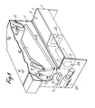
- the frame of the shears shown in Figures 1 and 2 comprises two lateral flanges 1, having a generally L-shaped contour, and which are arranged in two parallel vertical planes. At their upper part, these two flanges are joined by panels 2, 3 and 4 constituting in a way an open box in the shape of an inverted U. For ease of understanding of Figure 1, the front panel 3 has not been shown thereon.
- the support of the fixed lower blade 5 of the present shears consists of a closed hollow box, designated by the general reference 6, and which extends horizontally on the front of this shears, between the lower branches of the two lateral flanges 1.
- This box is fixed to the frame of the present shears only by its ends, in this case by welding the edges of its ends against the internal face of the two lateral flanges 1 and this, by weld beads 7.
- the lower blade 5 is fixed near the upper edge of one of the side walls of the present box, in this case the vertical wall 8 facing inward. Therefore the position of this blade is offset by a distance L relative to the center O of the hollow box 6, which it serves support- As already indicated, and as will be explained in more detail below, this arrangement allows to take advantage of the vertical forces, which are exerted on the fixed blade, to compensate for the deformations of its support in the horizontal direction.
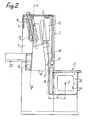
- the movable upper blade 9 of the present shears is fixed on the lower edge of a movable apron 10 comprising, at its ends, two vertical cheeks 11 arranged opposite the lateral flanges 1 of the frame.
- the movable deck 10 is not disposed in a vertical plane, but in a plane inclined rearward from the low plane making, with respect to the horizontal, an obtuse angle ⁇ of the order from 92 ° to 110 °, for example 98 °.
- the guide ramps provided on the rear edge of the side cheeks, and which move in contact with two fixed rollers 12, for their part have a reverse inclination. figure 3.
- this movable deck is controlled by two hydraulic cylinders 13 arranged at one and the other ends. As for its raising, it is provided by return springs 14 acting in traction. These are arranged diagonally so as to pull this deck both upwards and backwards (see FIG. 3), the upper points 15 for hooking these springs being indicated in FIG. 1.
- the inclination of the movable upper deck 10 aims to oppose an increase in the clearance between the two blades of the present shears, which was already the purpose of the particular mode of mounting the fixed blade on the frame.
- the arrangement provided in the shears according to the invention aims to use this vertical force to compensate for the horizontal bending set out above.
- This result is achieved by the fact that, in the shears according to the invention, the fixed blade 5 is fixed to one of the side walls of a hollow box 6 in a position offset relative to the theoretical center O of rotation of this box, when the latter undergoes a torsional force.
- the inclination of the upper apron 10 is intended to promote the buckling effect thereof so as to also contribute to the reduction of the play between the blades.
- this box can serve as housing for the reservoir 28 forming part of the hydraulic circuit for controlling the jacks 13.
- This circuit also comprises a hydraulic group 29 as well as a control block 30. As shown in FIG. 1, these are advantageously fixed to the outside of the machine on the external face of one of the side flanges of the frame, which facilitates access for maintenance and dismantling operations.
- this hydraulic circuit there is no need to describe the design of this hydraulic circuit, because it can be identical to those usually provided on conventional shears.
- the present shears are also equipped with a system making it possible to adjust its cutting angle, that is to say the angle ⁇ formed by the movable blade 9 relative to the horizontal.
- this system can be constituted by a movable stop 31 having several support notches of different depth and each of which is able to cooperate with an elastic stop 32 carried by the most raised end of the upper deck 10
- the adjustment can be carried out by maneuvering the movable stop 31 by hand in order to place one and the other of these notches opposite the stop 32.
- this manually controlled system can be replaced by a movable stop 33 constituted by a linear jack actuated by an electric motor 34.
- This stop is then as previously arranged opposite the elastic stop 32 carried by the movable deck 10.
Landscapes
- Engineering & Computer Science (AREA)
- Mechanical Engineering (AREA)
- Shearing Machines (AREA)
Applications Claiming Priority (2)
| Application Number | Priority Date | Filing Date | Title |
|---|---|---|---|
| FR8407637A FR2564346B1 (fr) | 1984-05-17 | 1984-05-17 | Cisaille hydraulique |
| FR8407637 | 1984-05-17 |
Publications (2)
| Publication Number | Publication Date |
|---|---|
| EP0161972A2 true EP0161972A2 (de) | 1985-11-21 |
| EP0161972A3 EP0161972A3 (de) | 1987-04-08 |
Family
ID=9304071
Family Applications (1)
| Application Number | Title | Priority Date | Filing Date |
|---|---|---|---|
| EP85400780A Withdrawn EP0161972A3 (de) | 1984-05-17 | 1985-04-19 | Hydraulische Schere |
Country Status (8)
| Country | Link |
|---|---|
| US (1) | US4624164A (de) |
| EP (1) | EP0161972A3 (de) |
| JP (1) | JPH078448B2 (de) |
| BR (1) | BR8502299A (de) |
| CA (1) | CA1238267A (de) |
| ES (1) | ES295982Y (de) |
| FR (1) | FR2564346B1 (de) |
| PT (1) | PT80470B (de) |
Cited By (1)
| Publication number | Priority date | Publication date | Assignee | Title |
|---|---|---|---|---|
| CN104384594A (zh) * | 2014-11-25 | 2015-03-04 | 江苏大学 | 超大型剪板机板料剪切边缘变形量自动补偿系统及方法 |
Families Citing this family (11)
| Publication number | Priority date | Publication date | Assignee | Title |
|---|---|---|---|---|
| US5237901A (en) * | 1992-04-06 | 1993-08-24 | Rohrer Special Machinery Inc. | Shear |
| US6152007A (en) * | 1997-02-05 | 2000-11-28 | Japan Cbm Corporation | Sheet cutter |
| GB2405117B (en) * | 2003-08-18 | 2006-05-10 | Vai Ind | Shear blade gap compensator |
| ITMN20060040A1 (it) * | 2006-05-19 | 2007-11-20 | Pe Srl | Dispositivo di taglio di un nastro in carta, plastica o materiale simile |
| US8616106B2 (en) * | 2007-02-27 | 2013-12-31 | Canon Kabushiki Kaisha | Sheet cutting apparatus and image forming apparatus |
| GB2469288A (en) * | 2009-04-07 | 2010-10-13 | Siemens Vai Metals Tech Ltd | Apparatus for shearing which offsets repulsive forces |
| WO2011012926A1 (en) * | 2009-07-29 | 2011-02-03 | Sidel S.P.A. | Cutting unit for labelling machines |
| JP5807417B2 (ja) * | 2011-07-14 | 2015-11-10 | 旭硝子株式会社 | 紙葉類の切断装置 |
| CN108472822B (zh) * | 2015-12-07 | 2020-04-03 | 艾利丹尼森零售信息服务公司 | 用于打印系统的切割机附件 |
| CN110709218B (zh) | 2017-05-01 | 2021-08-31 | 艾利丹尼森零售信息服务公司 | 独立切割装置 |
| CN116000362B (zh) * | 2023-02-09 | 2025-03-07 | 安徽东海裕祥智能装备科技有限公司 | 一种高精度闸式剪板机及刀口间隙精调方法 |
Family Cites Families (12)
| Publication number | Priority date | Publication date | Assignee | Title |
|---|---|---|---|---|
| US2734572A (en) * | 1956-02-14 | Camber adjuster for squaring shear - | ||
| US1139572A (en) * | 1914-04-03 | 1915-05-18 | Rogers Shear Company | Envelop-opener. |
| US1140897A (en) * | 1915-03-20 | 1915-05-25 | United Eng Foundry Co | Shears. |
| US1843362A (en) * | 1929-11-29 | 1932-02-02 | Cincinnati Shaper Co | Back brace for machine tool rams |
| US1885438A (en) * | 1929-11-29 | 1932-11-01 | Cincinnati Shaper Co | Metal shears |
| US2539602A (en) * | 1944-04-21 | 1951-01-30 | Cleveland Crane Eng | Shear press |
| GB831354A (en) * | 1957-08-19 | 1960-03-30 | Brookes Oldbury Ltd | Power operated shears |
| GB922933A (en) * | 1960-01-06 | 1963-04-03 | Steel Construction & Eng Co | Improvements in or relating to guillotines and press brakes |
| US3371569A (en) * | 1965-06-28 | 1968-03-05 | Pacific Press & Shear Corp | Shear machine or the like |
| GB1138803A (en) * | 1967-01-14 | 1969-01-01 | Steel Construction & Eng Co | Improvements in or relating to guillotines |
| US3791248A (en) * | 1972-08-14 | 1974-02-12 | Canron Inc | Shear machine knife adjustment |
| US4114491A (en) * | 1974-09-24 | 1978-09-19 | Hitachi Metals, Ltd. | Full rotation type paper web cutting device |
-
1984
- 1984-05-17 FR FR8407637A patent/FR2564346B1/fr not_active Expired
-
1985
- 1985-04-19 EP EP85400780A patent/EP0161972A3/de not_active Withdrawn
- 1985-04-26 US US06/727,608 patent/US4624164A/en not_active Expired - Fee Related
- 1985-05-07 CA CA000480962A patent/CA1238267A/en not_active Expired
- 1985-05-14 ES ES1985295982U patent/ES295982Y/es not_active Expired
- 1985-05-15 PT PT80470A patent/PT80470B/pt not_active IP Right Cessation
- 1985-05-16 BR BR8502299A patent/BR8502299A/pt not_active IP Right Cessation
- 1985-05-16 JP JP60104929A patent/JPH078448B2/ja not_active Expired - Lifetime
Cited By (2)
| Publication number | Priority date | Publication date | Assignee | Title |
|---|---|---|---|---|
| CN104384594A (zh) * | 2014-11-25 | 2015-03-04 | 江苏大学 | 超大型剪板机板料剪切边缘变形量自动补偿系统及方法 |
| CN104384594B (zh) * | 2014-11-25 | 2016-08-31 | 江苏大学 | 超大型剪板机板料剪切边缘变形量自动补偿系统及方法 |
Also Published As
| Publication number | Publication date |
|---|---|
| JPH078448B2 (ja) | 1995-02-01 |
| FR2564346B1 (fr) | 1987-11-13 |
| JPS60255306A (ja) | 1985-12-17 |
| PT80470A (fr) | 1985-06-01 |
| BR8502299A (pt) | 1986-01-21 |
| ES295982Y (es) | 1988-05-16 |
| ES295982U (es) | 1987-11-01 |
| EP0161972A3 (de) | 1987-04-08 |
| FR2564346A1 (fr) | 1985-11-22 |
| CA1238267A (en) | 1988-06-21 |
| US4624164A (en) | 1986-11-25 |
| PT80470B (pt) | 1987-05-29 |
Similar Documents
| Publication | Publication Date | Title |
|---|---|---|
| EP0161972A2 (de) | Hydraulische Schere | |
| FR2740743A1 (fr) | Glissiere verrouillable, notamment pour siege de vehicule automobile | |
| WO2009092946A2 (fr) | Glissière pour siège de véhicule et siège de véhicule comprenant une telle glissière | |
| FR2774083A1 (fr) | Dispositif elevateur perfectionne | |
| EP1818479B1 (de) | Perfektioniertes Schalungssystem für Hoch- oder Tiefbauten | |
| FR2537906A1 (fr) | Ratelier a consoles | |
| EP2112321B1 (de) | Rollladen, der mit einer Bremse ausgestattet ist | |
| EP3789246B1 (de) | Vorrichtung zum verstauen mit schubladen für ein kraftfahrzeug | |
| EP3767049A1 (de) | Pergola beinhaltend eine tragende struktur und ein faltbares beschattungselement | |
| FR2989364A1 (fr) | Treuil de relevage d'un auvent de protection d'une structure pliable de travail en encorbellement et methode de relevage | |
| EP3655285B1 (de) | Einziehbarer fahrzeugsitz | |
| FR2876959A1 (fr) | Dispositif d'ouvrant pour vehicule automobile | |
| FR2936989A1 (fr) | Monte-charge pour toit d'un vehicule terrestre | |
| FR2618829A1 (fr) | Perfectionnement aux dispositifs de securite evitant le basculement d'une paire de banches | |
| EP0543706A1 (de) | Vorrichtung zum automatischen Kuppeln einer Sicherheitsgurtverankerung mit dem Boden eines Fahrzeuges | |
| FR2811344A1 (fr) | Glissiere de securite routiere en bois avec renfort metal continu insere dans le rondin | |
| EP0741206B1 (de) | Überlaufklappenwehr | |
| EP0943826B1 (de) | Verbindungsvorrichtung zwischen einer Stange und einer Bohrung des Antirollstabes eines Fahrzeuges | |
| EP0012077A1 (de) | Hilfsvorrichtung zum Öffnen eines zusammenklappbaren Wohnwagens mit starren Wänden | |
| FR2706500A1 (fr) | Barrière repliable. | |
| WO2026003444A1 (fr) | Raidisseur optimisé pour porte latérale de véhicule automobile | |
| EP3626496A1 (de) | Verstärkte sicherheitsseitentür für fahrzeug | |
| EP4517034A1 (de) | Quertraversfreies schiebetor | |
| FR2539680A1 (fr) | Porte vitree de vehicule automobile, equipee d'un leve-vitre a cremaillere | |
| FR2492355A1 (fr) | Monte-charge |
Legal Events
| Date | Code | Title | Description |
|---|---|---|---|
| PUAI | Public reference made under article 153(3) epc to a published international application that has entered the european phase |
Free format text: ORIGINAL CODE: 0009012 |
|
| AK | Designated contracting states |
Designated state(s): AT BE CH DE GB IT LI NL SE |
|
| PUAL | Search report despatched |
Free format text: ORIGINAL CODE: 0009013 |
|
| AK | Designated contracting states |
Kind code of ref document: A3 Designated state(s): AT BE CH DE GB IT LI NL SE |
|
| 17P | Request for examination filed |
Effective date: 19870610 |
|
| 17Q | First examination report despatched |
Effective date: 19881010 |
|
| STAA | Information on the status of an ep patent application or granted ep patent |
Free format text: STATUS: THE APPLICATION IS DEEMED TO BE WITHDRAWN |
|
| 18D | Application deemed to be withdrawn |
Effective date: 19890221 |
|
| RIN1 | Information on inventor provided before grant (corrected) |
Inventor name: PASSA, RENE |