EP0161800A2 - Methods and apparatus for erecting tray-type cartons - Google Patents
Methods and apparatus for erecting tray-type cartons Download PDFInfo
- Publication number
- EP0161800A2 EP0161800A2 EP85302523A EP85302523A EP0161800A2 EP 0161800 A2 EP0161800 A2 EP 0161800A2 EP 85302523 A EP85302523 A EP 85302523A EP 85302523 A EP85302523 A EP 85302523A EP 0161800 A2 EP0161800 A2 EP 0161800A2
- Authority
- EP
- European Patent Office
- Prior art keywords
- tabs
- folding
- panels
- side wall
- punch
- Prior art date
- Legal status (The legal status is an assumption and is not a legal conclusion. Google has not performed a legal analysis and makes no representation as to the accuracy of the status listed.)
- Granted
Links
- 238000000034 method Methods 0.000 title claims description 19
- 230000002093 peripheral effect Effects 0.000 claims abstract description 19
- 239000000463 material Substances 0.000 claims abstract description 5
- 230000033001 locomotion Effects 0.000 claims description 13
- 238000007789 sealing Methods 0.000 claims description 5
- 239000000853 adhesive Substances 0.000 claims description 4
- 230000001070 adhesive effect Effects 0.000 claims description 4
- 230000003213 activating effect Effects 0.000 claims description 2
- 239000011248 coating agent Substances 0.000 description 3
- 238000000576 coating method Methods 0.000 description 3
- 241000282472 Canis lupus familiaris Species 0.000 description 1
- 230000005540 biological transmission Effects 0.000 description 1
- 230000015572 biosynthetic process Effects 0.000 description 1
- 235000013305 food Nutrition 0.000 description 1
- 238000004806 packaging method and process Methods 0.000 description 1
- 229920001225 polyester resin Polymers 0.000 description 1
- 239000004645 polyester resin Substances 0.000 description 1
- -1 polyethylene terephthalate Polymers 0.000 description 1
- 229920000139 polyethylene terephthalate Polymers 0.000 description 1
- 239000005020 polyethylene terephthalate Substances 0.000 description 1
- 230000003068 static effect Effects 0.000 description 1
Images


Classifications
-
- B—PERFORMING OPERATIONS; TRANSPORTING
- B31—MAKING ARTICLES OF PAPER, CARDBOARD OR MATERIAL WORKED IN A MANNER ANALOGOUS TO PAPER; WORKING PAPER, CARDBOARD OR MATERIAL WORKED IN A MANNER ANALOGOUS TO PAPER
- B31B—MAKING CONTAINERS OF PAPER, CARDBOARD OR MATERIAL WORKED IN A MANNER ANALOGOUS TO PAPER
- B31B70/00—Making flexible containers, e.g. envelopes or bags
-
- B—PERFORMING OPERATIONS; TRANSPORTING
- B31—MAKING ARTICLES OF PAPER, CARDBOARD OR MATERIAL WORKED IN A MANNER ANALOGOUS TO PAPER; WORKING PAPER, CARDBOARD OR MATERIAL WORKED IN A MANNER ANALOGOUS TO PAPER
- B31B—MAKING CONTAINERS OF PAPER, CARDBOARD OR MATERIAL WORKED IN A MANNER ANALOGOUS TO PAPER
- B31B50/00—Making rigid or semi-rigid containers, e.g. boxes or cartons
-
- B—PERFORMING OPERATIONS; TRANSPORTING
- B31—MAKING ARTICLES OF PAPER, CARDBOARD OR MATERIAL WORKED IN A MANNER ANALOGOUS TO PAPER; WORKING PAPER, CARDBOARD OR MATERIAL WORKED IN A MANNER ANALOGOUS TO PAPER
- B31B—MAKING CONTAINERS OF PAPER, CARDBOARD OR MATERIAL WORKED IN A MANNER ANALOGOUS TO PAPER
- B31B2100/00—Rigid or semi-rigid containers made by folding single-piece sheets, blanks or webs
- B31B2100/002—Rigid or semi-rigid containers made by folding single-piece sheets, blanks or webs characterised by the shape of the blank from which they are formed
- B31B2100/0024—Rigid or semi-rigid containers made by folding single-piece sheets, blanks or webs characterised by the shape of the blank from which they are formed having all side walls attached to the bottom
-
- B—PERFORMING OPERATIONS; TRANSPORTING
- B31—MAKING ARTICLES OF PAPER, CARDBOARD OR MATERIAL WORKED IN A MANNER ANALOGOUS TO PAPER; WORKING PAPER, CARDBOARD OR MATERIAL WORKED IN A MANNER ANALOGOUS TO PAPER
- B31B—MAKING CONTAINERS OF PAPER, CARDBOARD OR MATERIAL WORKED IN A MANNER ANALOGOUS TO PAPER
- B31B2110/00—Shape of rigid or semi-rigid containers
- B31B2110/10—Shape of rigid or semi-rigid containers having a cross section of varying size or shape, e.g. conical or pyramidal
-
- B—PERFORMING OPERATIONS; TRANSPORTING
- B31—MAKING ARTICLES OF PAPER, CARDBOARD OR MATERIAL WORKED IN A MANNER ANALOGOUS TO PAPER; WORKING PAPER, CARDBOARD OR MATERIAL WORKED IN A MANNER ANALOGOUS TO PAPER
- B31B—MAKING CONTAINERS OF PAPER, CARDBOARD OR MATERIAL WORKED IN A MANNER ANALOGOUS TO PAPER
- B31B2110/00—Shape of rigid or semi-rigid containers
- B31B2110/30—Shape of rigid or semi-rigid containers having a polygonal cross section
- B31B2110/35—Shape of rigid or semi-rigid containers having a polygonal cross section rectangular, e.g. square
-
- B—PERFORMING OPERATIONS; TRANSPORTING
- B31—MAKING ARTICLES OF PAPER, CARDBOARD OR MATERIAL WORKED IN A MANNER ANALOGOUS TO PAPER; WORKING PAPER, CARDBOARD OR MATERIAL WORKED IN A MANNER ANALOGOUS TO PAPER
- B31B—MAKING CONTAINERS OF PAPER, CARDBOARD OR MATERIAL WORKED IN A MANNER ANALOGOUS TO PAPER
- B31B2120/00—Construction of rigid or semi-rigid containers
- B31B2120/70—Construction of rigid or semi-rigid containers having corrugated or pleated walls
-
- B—PERFORMING OPERATIONS; TRANSPORTING
- B31—MAKING ARTICLES OF PAPER, CARDBOARD OR MATERIAL WORKED IN A MANNER ANALOGOUS TO PAPER; WORKING PAPER, CARDBOARD OR MATERIAL WORKED IN A MANNER ANALOGOUS TO PAPER
- B31B—MAKING CONTAINERS OF PAPER, CARDBOARD OR MATERIAL WORKED IN A MANNER ANALOGOUS TO PAPER
- B31B2160/00—Shape of flexible containers
- B31B2160/10—Shape of flexible containers rectangular and flat, i.e. without structural provision for thickness of contents
-
- B—PERFORMING OPERATIONS; TRANSPORTING
- B31—MAKING ARTICLES OF PAPER, CARDBOARD OR MATERIAL WORKED IN A MANNER ANALOGOUS TO PAPER; WORKING PAPER, CARDBOARD OR MATERIAL WORKED IN A MANNER ANALOGOUS TO PAPER
- B31B—MAKING CONTAINERS OF PAPER, CARDBOARD OR MATERIAL WORKED IN A MANNER ANALOGOUS TO PAPER
- B31B50/00—Making rigid or semi-rigid containers, e.g. boxes or cartons
- B31B50/26—Folding sheets, blanks or webs
- B31B50/44—Folding sheets, blanks or webs by plungers moving through folding dies
Definitions
- This invention relates to methods and apparatus for erecting tray-type cartons, more particularly for erecting from a blank of foldable sheet material a rectangular tray-type carton of the kind having a base formed from a base panel of the blank, a side wall upstanding from the base and formed from four side wall panels, gusset folds secured against the side wall at the corners of the carton and formed from gusset panels by which the side wall panels are joined integrally together, and a continuous peripheral flange outturned from the side wall around the mouth of the carton, the flange being formed from elongate panels carried by the side wall panels and formed at their ends with tabs which are secured together in overlapping relation at the corners of the carton.
- a flat closure lid can be attached to the carton, for example by heat-sealing the margin of the lid to the upper surface of the peripheral flange.
- the folding is effected by a punch and die arrangement.
- This process has proved commercially successful but it does in practice require the use of a number of separate operating stations and an indexing conveyor to stop the movement of the cartons at the second station for folding of the two pairs of opposed elongate panels.
- An object of the present invention is to provide a process and apparatus of a simplified nature which will operate with a continuously moving conveyor, avoiding the need for an indexing movement.
- a method of erecting a carton of the kind referred to above comprises the steps of:-
- the folding up of the tabs which are to be uppermost may be effected by means of pivotal fingers which are raised to fold the tabs upwards while the base of the blank is restrained by the punch against upward movement.
- the outward folding of the pair of opposed elongate panels which carry the uppermost tabs may be effected by a pair of folding bars pivotally mounted on the punch and actuated at the end of the movement of the punch through the die.
- the partially erected carton may be held on the punch by retractable holding bars while the elongate panels which carry the uppermost tabs are folded.
- the outward folding of the other pair of elongate panels may be initiated by oscillating fingers actuated in timed relationship with the movement of the carton.
- the folding of this other pair of elongate panels may be completed by engagement with profiled bars disposed on each side of the conveyor.
- the hot gas may be directed at the surfaces of the tabs by means of laterally directed jets of hot air which travel parallel to the conveyor and at the same speed.
- the overlapping tabs may be secured together by pressure rollers.
- the invention also resides in apparatus for erecting a blank of foldable sheet material into a rectangular tray-type carton of the kind described above, wherein the apparatus comprises:-
- the folding means arranged to be operated on completion of the stroke of the punch may comprise a pair of folding bars pivotally mounted on the punch and actuated by a rod which is axially movable within a punch operating rod on which the punch is fixed.
- a pair of retractable holding bars may be mounted adjacent to the die for holding the partially erected carton on the punch at the end of the stroke of the punch. These holding bars may be mechanically linked to the pivotal fingers so as to retract the fingers for receipt of the next blank as the holding bars are retracted to release the preceding blank from the punch.
- the folding means for folding the other pair of opposed elongate panels may comprise a pair of oscillating fingers mounted on respective shafts adjacent and parallel to each side of the conveyor and a linkage arranged to actuate the oscillating fingers to initiate the folding in timed relationship with the movement of the carton along the conveyor.
- These folding means may further comprise a pair of profiled bars disposed adjacent and parallel to each side of the conveyor downstream from the oscillating fingers.
- the means for directing hot gas at the surfaces of the tabs may comprise devices arranged at each side of the conveyor and arranged to produce laterally directed jets of hot air which travel parallel to the conveyor and at the same speed.
- the sealing means may comprise pressure rollers.
- a blank 10 for forming a rectangular tray-type packaging container for a food product is cut and creased from cardboard which is provided on one surface, that is to say, the surface which is to form the interior of the carton, with an overall coating of a polyester resin such as polyethylene terephthalate.
- the coating which is heat-resistant, is not shown in the drawing but will be understood to be located on the surface which is visible to the reader. In known manner it is heat-sealable to itself under conditions of heat and pressure.
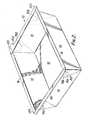
- the blank 10 is generally rectangular and is internally sub-divided by crease lines to form it with a rectangular base panel 12, four side wall panels 14 disposed at the four sides of the base panel, gusset panels 16A, 16B at the corners of the blank and joining adjacent side wall panels 14 integrally together, and elongate panels 18, 181 carried individually by the side wall panels around the periphery of the blank and having projecting tabs 20, 201 at their ends.
- One of the tabs 201 is enlarged in width and length as shown at 202.
- the base panel 12 forms the carton base 22
- the side wall panels 14 form the carton side wall 24
- the gusset panels 16A, 16B are folded against one another to form gusset folds 26 which are disposed and secured against the side wall 24
- the elongate panels 18, 181 form an outturned, horizontal peripheral flange 28 which extends continuously around the carton, with a projecting tab 281.
- the peripheral flange 28 provides a convenient surface on which a closure lid having a projecting tab corresponding to tab 281 may be attached. The tabs facilitate removal of the lid by the purchaser when the container is to be opened.
- the side wall is made upwardly and outwardly tapering by suitable inclination of the crease lines defining the ends of its side wall panels 14, and the gusset folds 26 are secured against the side wall at tab portions 30 of the gusset panels 16A, which are brought into contact with the side wall when the gusset folds are formed and which are subsequently heat-sealed to the side wall.
- the tabs 20, 201 are overlapped in pairs at the corners of the carton and heat-sealed together to form the continuous peripheral flange 28, the uppermost ones 201 of the tabs being each provided by the elongate panels 181 of two opposed side wall panels 14. The significance of this will become apparent from the description which follows.
- the apparatus for erecting the blank 10 of Figure 1 to form the tray-type carton 110 of Figure 2 is diagrammatically shown to comprise two initial forming sections 40, 41 which are essentially identical and are illustrated in more detail in Figures 4 and 5.
- Partially erected cartons 42 pass from the stations 40, 41 via a conveyor 43 and their second or lateral pair of elongate panels 18 are folded outwardly as they pass folding means 44 indicated diagrammatically in Figure 3 and illustrated in more detail in Figures 6 and 7.
- the cartons 42 are then carried past means 45 which direct lateral jets of hot air onto the surfaces of the upstanding tabs, which are then pressed flat on to the underlying tabs by pressure rollers 46.
- the tray-type cartons are then complete and can be stacked ready for filling.
- each initial forming station 40, 41 comprises a frame 50 in which a punch support 51 is vertically movable.
- the punch 52 is fixed to the lower end of a punch operating rod 53 whose upper end is carried by the punch support 51.
- a die 54 is supported in the lower part of the frame 50.
- Blanks 10 are fed to support bars 55 in a direction at right angles to the plane of the paper in Figure 4.
- Pivotal fingers 56 are mounted on shafts 57 supported on the frame 50.
- a pair of folding bars 58 are pivotally mounted in the punch 52.
- the folding bars 58 can be pivoted about their pivots 59 by means of a rod 60 axially movable within the punch operating rod 53, through an extension 61 on the folding bar 58 engaging in a recess in a lug 62 mounted on a bar 63 carried by the lower end of the rod 60.
- the upper end of the rod 60 is connected by a cross-bar 64 to the vertically movable piston of a pneumatic cylinder 65. Raising the rod 60 by means of the pneumatic cylinder 65 causes the folding bar 58 to move from the position shown in full lines in Figure 5 to that shown in chain lines.
- a pair of retractable holding bars 66, 67 are pivotally mounted adjacent the die 54 and connected by linkages 68, 69 to the pivotal fingers 56.
- holding bar 66 is shown in the operative position adjacent to the punch 52 at the lower end of its stroke while holding bar 67 is shown in its retracted position. It will be seen that when the holding bars are in their retracted position the pivotal fingers 56 are also in their retracted position ready to receive a blank.
- the punch 52 then continues its downward stroke and forces the blank 10 through the die 54, thereby forming the side wall 24 of the carton by folding up the side wall panels 14 in relation to the base panel 12, while the gusset panels 16A, 16B are folded against one another to form gusset folds 26 which are disposed and secured against the side wall 24.
- the elongate panels 18, 181 remain as coplanar extensions of their respective side wall panels with the exception of the tabs 201.
- the partially erected carton is received within the holding bars 66, 67.
- the pneumatic cylinder 65 is operated to pivot the folding bars 58 to the position shown in chain lines in Figure 5 so as to fold the elongate panels 181 outwardly.
- the folding bars 58 fold the panels 181 sufficiently far beyond the horizontal that on springing back they will adopt an approximately horizontal position as shown on the right-hand side of Figure 5.
- the holding bars 66, 67 are now retracted to release the partially erected carton 42 and to allow it to fall onto the conveyor 43 for onward transmission to the folding means 44 shown in more detail i n Figures 6 and 7, while the punch 52 is retracted to position 521.
- the folding means for folding the other pair of opposed elongated panels 18 comprise firstly a pair of oscillating fingers 70 (of which only one is shown in Figure 6 and the other in Figure 7) mounted on respective shafts 71 adjacent and parallel to each side of the conveyor 43 which propels the cartons 42 by means of dogs 72.
- the shafts 71 are connected by a linkage 73 to the conveyor driving mechanism so as to rotate the oscillating fingers 70 about the axes of shafts 71 from the inoperative position shown in Figure 7 to the operative position of Figure 6, to initiate folding of the panels 18 in timed relationship with the movement of the carton 42, as the conveyor 43 moves it into the position shown in Figure 6.
- the folding means 44 further comprises a pair of profiled bars or ploughs 74 disposed one on each side of the conveyor 43 and parallel to it, downstream from the oscillating fingers-70.
- the profiled bars 74 each co-operate with a similarly profiled lower anvil bar 75 to receive the elongate panel 18 and fold it downwardly to such an extent that, on springing back, it will assume a substantially horizontal position.
- a static horizontal hold-down bar 76 is provided as shown in Figure 7.
- the method and apparatus described provide a relatively simple and highly efficient means of erecting tray-type cartons from blanks as shown in Figure 1, avoiding the need for indexing motion of the conveyor.
Landscapes
- Making Paper Articles (AREA)
- Auxiliary Devices For And Details Of Packaging Control (AREA)
- Cartons (AREA)
- Nitrogen Condensed Heterocyclic Rings (AREA)
- Electrically Operated Instructional Devices (AREA)
- Feedback Control In General (AREA)
- Supplying Of Containers To The Packaging Station (AREA)
- Closing Of Containers (AREA)
- Basic Packing Technique (AREA)
- Containers Having Bodies Formed In One Piece (AREA)
Abstract
Description
- This invention relates to methods and apparatus for erecting tray-type cartons, more particularly for erecting from a blank of foldable sheet material a rectangular tray-type carton of the kind having a base formed from a base panel of the blank, a side wall upstanding from the base and formed from four side wall panels, gusset folds secured against the side wall at the corners of the carton and formed from gusset panels by which the side wall panels are joined integrally together, and a continuous peripheral flange outturned from the side wall around the mouth of the carton, the flange being formed from elongate panels carried by the side wall panels and formed at their ends with tabs which are secured together in overlapping relation at the corners of the carton. A flat closure lid can be attached to the carton, for example by heat-sealing the margin of the lid to the upper surface of the peripheral flange.
- In the erection of rectangular tray-type cartons having peripheral flanges from flat blanks, it is known to form the flanges by the same operation as is used to fold up the side wall panels of the cartons in relation to the carton bases. Such a method, however, has several disadvantages attendant upon the formation of the peripheral flanges. It is also known from our copending British Patent Application No. 8213491 (Publication No. 2120161), as a first step in the folding process, to fold up from the plane of the blank those of the tabs which are to be uppermost in the erected carton, so that they will not interfere with the other tabs but will be correctly positioned during the subsequent steps of the folding process. In the process described in our said Application, the subsequent steps comprise:-
- (a) at a first station, forming the side wall by folding up the side wall panels in relation to the base panel whilst folding the gusset panels to form the gusset folds, such folding being accompanied by movement of the elongate panels with the side wall panels as coplanar extensions thereof with the exception of the said uppermost ones of the tabs,
- (b) moving the partially erected carton from. the first station to a second station,
- (c) at the second station, folding the elongate panels outwardly in relation to the side wall and into generally coplanar relation with one another, with the said uppermost tabs overlying other ones of the tabs at the corners of the carton, and
- (d) securing the overlapping tabs together at the corners of the carton to form a continuous peripheral flange.
- In the preferred embodiment the folding is effected by a punch and die arrangement. This process has proved commercially successful but it does in practice require the use of a number of separate operating stations and an indexing conveyor to stop the movement of the cartons at the second station for folding of the two pairs of opposed elongate panels.
- An object of the present invention is to provide a process and apparatus of a simplified nature which will operate with a continuously moving conveyor, avoiding the need for an indexing movement.
- According to the present invention, a method of erecting a carton of the kind referred to above comprises the steps of:-
- (a) at an initial forming station incorporating a punch and die arrangement, folding up from th plane of the blank those of the tabs which are to be uppermost in the erected carton, then forcing the blank through the die by means of the punch so as to form the side wall by folding up the side wall panels in relation to the base panel whilst folding the gusset panels to form the gusset folds, the elongate panels moving with the side wall panels as coplanar extensions thereof with the exception of the said uppermost ones of the tabs, and then, on completion of the stroke of the punch, folding outwardly the pair of opposed elongate panels which carry the said uppermost ones of the tabs,
- (b) transferring the partially erected carton from the punch to a conveyor which moves continuously in a direction perpendicular to the length of the already folded pair of elongate panels and carrying the carton on said conveyor while folding the other pair of elongate panels outwardly in relation to the side wall and into generally coplanar relation with the first mentioned pair;
- (c) directing hot gas at the surfaces of said tabs which are to be joined together so as to activate an adhesive provided thereon, and
- (d) securing the overlapping tabs together at the corners of the carton to form the continuous peripheral flange.
- By thus performing the folding of the first pair of elongate panels at the initial forming station, it becomes possible in accordance with the process outlined above to perform the folding of the second pair and the other necessary operations while carrying the carton along the continuously moving conveyor.
- At the initial forming station, the folding up of the tabs which are to be uppermost may be effected by means of pivotal fingers which are raised to fold the tabs upwards while the base of the blank is restrained by the punch against upward movement. The outward folding of the pair of opposed elongate panels which carry the uppermost tabs may be effected by a pair of folding bars pivotally mounted on the punch and actuated at the end of the movement of the punch through the die. The partially erected carton may be held on the punch by retractable holding bars while the elongate panels which carry the uppermost tabs are folded.
- The outward folding of the other pair of elongate panels may be initiated by oscillating fingers actuated in timed relationship with the movement of the carton. The folding of this other pair of elongate panels may be completed by engagement with profiled bars disposed on each side of the conveyor.
- The hot gas may be directed at the surfaces of the tabs by means of laterally directed jets of hot air which travel parallel to the conveyor and at the same speed.
- The overlapping tabs may be secured together by pressure rollers.
- The invention also resides in apparatus for erecting a blank of foldable sheet material into a rectangular tray-type carton of the kind described above, wherein the apparatus comprises:-
- (a) an initial forming station incorporating pivotal fingers arranged to be operated to fold up from the plane of the blank those of the tabs which are to be uppermost in the erected carton, a punch arranged to force the blank through a die to form the side wall by folding up the side wall panels in relation to the base panel whilst folding the gusset panels to form the gusset folds, the elongate panels moving with the side wall panels as coplanar extensions thereof with the exception of the said uppermost ones of the tabs, and folding means arranged to be operated on completion of the stroke of the punch to fold outwardly the pair of opposed panels which carry the said uppermost ones of the tabs,
- (b) a conveyor arranged to receive the partially erected carton from the first station and to transport it continuously through the remainder of the apparatus in a direction perpendicular to the length of the already folded pair of elongate panels,
- (c) folding means for folding the other pair of opposed elongate panels outwardly in relation to the side wall so as to form the peripheral flange,
- (d) means for directing hot gas at the surfaces of the tabs which are to be joined together for activating an adhesive provided thereon, and
- (e) sealing means for pressing the overlapping tabs together to bond them together and thus complete the peripheral flange.
- The folding means arranged to be operated on completion of the stroke of the punch may comprise a pair of folding bars pivotally mounted on the punch and actuated by a rod which is axially movable within a punch operating rod on which the punch is fixed.
- A pair of retractable holding bars may be mounted adjacent to the die for holding the partially erected carton on the punch at the end of the stroke of the punch. These holding bars may be mechanically linked to the pivotal fingers so as to retract the fingers for receipt of the next blank as the holding bars are retracted to release the preceding blank from the punch.
- The folding means for folding the other pair of opposed elongate panels may comprise a pair of oscillating fingers mounted on respective shafts adjacent and parallel to each side of the conveyor and a linkage arranged to actuate the oscillating fingers to initiate the folding in timed relationship with the movement of the carton along the conveyor. These folding means may further comprise a pair of profiled bars disposed adjacent and parallel to each side of the conveyor downstream from the oscillating fingers.
- The means for directing hot gas at the surfaces of the tabs may comprise devices arranged at each side of the conveyor and arranged to produce laterally directed jets of hot air which travel parallel to the conveyor and at the same speed.
- The sealing means may comprise pressure rollers.
- A specific embodiment of the invention will now be described by way of example and with reference to the accompanying drawings, in which:-
- Figure 1 is a plan view of a carton blank for erection to form a tray-type carton having a peripheral flange,
- Figure 2 is a perspective view of the carton erected from the blank of Figure 1,
- Figure 3 is a diagrammatic plan view of apparatus for erecting cartons as shown in Figure 2 from blanks as shown in Figure 1,
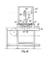
- Figure 4 is a diagrammatic elevation of an initial forming station forming part of the apparatus of Figure 3,
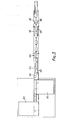
- Figure 5 is a part-sectional elevation, to a larger scale, of the essential working integers of the initial forming station,
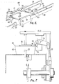
- Figure 6 is a perspective view of a carton being carried from the initial forming station and having its second pair of flanges folded, and
- Figure 7 is a diagrammatic end elevation of the conveyor and folding mechanism shown in Figure 6.
- Referring now to Figure 1, a blank 10 for forming a rectangular tray-type packaging container for a food product is cut and creased from cardboard which is provided on one surface, that is to say, the surface which is to form the interior of the carton, with an overall coating of a polyester resin such as polyethylene terephthalate. The coating, which is heat-resistant, is not shown in the drawing but will be understood to be located on the surface which is visible to the reader. In known manner it is heat-sealable to itself under conditions of heat and pressure.
- The blank 10 is generally rectangular and is internally sub-divided by crease lines to form it with a
rectangular base panel 12, fourside wall panels 14 disposed at the four sides of the base panel,gusset panels side wall panels 14 integrally together, andelongate panels tabs tabs 201 is enlarged in width and length as shown at 202. In the erected carton 110 (Figure 2) thebase panel 12 forms the carton base 22, theside wall panels 14 form the carton side wall 24, thegusset panels elongate panels - It will be seen in Figures 1 and 2 that the side wall is made upwardly and outwardly tapering by suitable inclination of the crease lines defining the ends of its
side wall panels 14, and the gusset folds 26 are secured against the side wall at tab portions 30 of thegusset panels 16A, which are brought into contact with the side wall when the gusset folds are formed and which are subsequently heat-sealed to the side wall. Furthermore, it should be noted that thetabs uppermost ones 201 of the tabs being each provided by theelongate panels 181 of two opposedside wall panels 14. The significance of this will become apparent from the description which follows. - Referring now to Figure 3, the apparatus for erecting the blank 10 of Figure 1 to form the tray-type carton 110 of Figure 2 is diagrammatically shown to comprise two initial forming
sections cartons 42 pass from thestations conveyor 43 and their second or lateral pair ofelongate panels 18 are folded outwardly as they pass folding means 44 indicated diagrammatically in Figure 3 and illustrated in more detail in Figures 6 and 7. Thecartons 42 are then carriedpast means 45 which direct lateral jets of hot air onto the surfaces of the upstanding tabs, which are then pressed flat on to the underlying tabs bypressure rollers 46. The tray-type cartons are then complete and can be stacked ready for filling. - As shown in Figures 4 and 5, each initial forming
station frame 50 in which apunch support 51 is vertically movable. Thepunch 52 is fixed to the lower end of apunch operating rod 53 whose upper end is carried by thepunch support 51. A die 54 is supported in the lower part of theframe 50.Blanks 10 are fed to supportbars 55 in a direction at right angles to the plane of the paper in Figure 4.Pivotal fingers 56, more clearly seen in Figure 5, are mounted onshafts 57 supported on theframe 50. - A pair of folding bars 58, of which only one is shown in Figure 5, are pivotally mounted in the
punch 52. The folding bars 58 can be pivoted about theirpivots 59 by means of arod 60 axially movable within thepunch operating rod 53, through anextension 61 on thefolding bar 58 engaging in a recess in alug 62 mounted on abar 63 carried by the lower end of therod 60. The upper end of therod 60 is connected by a cross-bar 64 to the vertically movable piston of apneumatic cylinder 65. Raising therod 60 by means of thepneumatic cylinder 65 causes thefolding bar 58 to move from the position shown in full lines in Figure 5 to that shown in chain lines. - A pair of retractable holding bars 66, 67 are pivotally mounted adjacent the
die 54 and connected bylinkages pivotal fingers 56. In Figure 5, holdingbar 66 is shown in the operative position adjacent to thepunch 52 at the lower end of its stroke while holdingbar 67 is shown in its retracted position. It will be seen that when the holding bars are in their retracted position thepivotal fingers 56 are also in their retracted position ready to receive a blank. - In use, when a blank 10 has been fed into position as shown in chain lines in Figure 5, the
punch 52 is lowered from its upper position shown at 521 to the position shown at 522 where it contacts the upper surface of the blank. Theshafts 57 are then rotated to raise thefingers 56 against the tabs 201 (Figures 1 and 2) and to fold them up from the plane of the blank. Thetabs 201 are of course those which are to be uppermost in the erected carton. At the same time, the rotation of theshafts 57 moves the holding bars 66, 67 into their operative position as shown at the left-hand side of Figure 5. - The
punch 52 then continues its downward stroke and forces the blank 10 through thedie 54, thereby forming the side wall 24 of the carton by folding up theside wall panels 14 in relation to thebase panel 12, while thegusset panels elongate panels tabs 201. - On completion of the stroke of the
punch 52 to the position shown in full lines in Figure 5, the partially erected carton is received within the holding bars 66, 67. Thepneumatic cylinder 65 is operated to pivot the folding bars 58 to the position shown in chain lines in Figure 5 so as to fold theelongate panels 181 outwardly. The folding bars 58 fold thepanels 181 sufficiently far beyond the horizontal that on springing back they will adopt an approximately horizontal position as shown on the right-hand side of Figure 5. - The holding bars 66, 67 are now retracted to release the partially erected
carton 42 and to allow it to fall onto theconveyor 43 for onward transmission to the folding means 44 shown in more detail i n Figures 6 and 7, while thepunch 52 is retracted toposition 521. - As shown in Figures 6 and 7, the folding means for folding the other pair of opposed
elongated panels 18 comprise firstly a pair of oscillating fingers 70 (of which only one is shown in Figure 6 and the other in Figure 7) mounted onrespective shafts 71 adjacent and parallel to each side of theconveyor 43 which propels thecartons 42 by means ofdogs 72. Theshafts 71 are connected by alinkage 73 to the conveyor driving mechanism so as to rotate theoscillating fingers 70 about the axes ofshafts 71 from the inoperative position shown in Figure 7 to the operative position of Figure 6, to initiate folding of thepanels 18 in timed relationship with the movement of thecarton 42, as theconveyor 43 moves it into the position shown in Figure 6. - The folding means 44 further comprises a pair of profiled bars or ploughs 74 disposed one on each side of the
conveyor 43 and parallel to it, downstream from the oscillating fingers-70. The profiled bars 74 each co-operate with a similarly profiledlower anvil bar 75 to receive theelongate panel 18 and fold it downwardly to such an extent that, on springing back, it will assume a substantially horizontal position. In order to stabilise thecarton 42 during the folding operation, a static horizontal hold-downbar 76 is provided as shown in Figure 7. - On leaving the folding means 44, the peripheral flange 28 is complete except that the
tabs 201 are still upstanding as in Figure 6. The carton is now traversed past devices 45 (Figure 3) arranged at each side of the conveyor for producing laterally directed jets of hot air which impinge on thetabs 201 and travel parallel to the conveyor and at the same speed, so as to activate the heat-sealable coating on the surface of the tabs. Devices suitable for producing such travelling jets of hot air are described and claimed in our British Patent Application No. 8411522. - Finally the
carton 42 is carriedpast pressure rollers 46 which co-act with support bars (not shown) to press thetabs 201 into contact with thetabs 20 and seal them together. - The method and apparatus described provide a relatively simple and highly efficient means of erecting tray-type cartons from blanks as shown in Figure 1, avoiding the need for indexing motion of the conveyor.
Claims (16)
Priority Applications (1)
| Application Number | Priority Date | Filing Date | Title |
|---|---|---|---|
| AT85302523T ATE44495T1 (en) | 1984-05-04 | 1985-04-10 | METHOD AND DEVICE FOR ERECTING TROGA-LIKE BOXES. |
Applications Claiming Priority (2)
| Application Number | Priority Date | Filing Date | Title |
|---|---|---|---|
| GB8411523 | 1984-05-04 | ||
| GB08411523A GB2158392B (en) | 1984-05-04 | 1984-05-04 | Erecting trays having peripheral flanges |
Publications (3)
| Publication Number | Publication Date |
|---|---|
| EP0161800A2 true EP0161800A2 (en) | 1985-11-21 |
| EP0161800A3 EP0161800A3 (en) | 1988-02-10 |
| EP0161800B1 EP0161800B1 (en) | 1989-07-12 |
Family
ID=10560514
Family Applications (1)
| Application Number | Title | Priority Date | Filing Date |
|---|---|---|---|
| EP85302523A Expired EP0161800B1 (en) | 1984-05-04 | 1985-04-10 | Methods and apparatus for erecting tray-type cartons |
Country Status (18)
| Country | Link |
|---|---|
| US (1) | US4636187A (en) |
| EP (1) | EP0161800B1 (en) |
| JP (1) | JPS60240444A (en) |
| AT (1) | ATE44495T1 (en) |
| AU (1) | AU583502B2 (en) |
| CA (1) | CA1235933A (en) |
| DE (1) | DE3571413D1 (en) |
| DK (1) | DK159604C (en) |
| ES (1) | ES8609031A1 (en) |
| FI (1) | FI74238C (en) |
| GB (1) | GB2158392B (en) |
| IE (1) | IE56432B1 (en) |
| IS (1) | IS3006A7 (en) |
| NO (1) | NO165791C (en) |
| NZ (1) | NZ211828A (en) |
| PT (1) | PT80381B (en) |
| SG (1) | SG11689G (en) |
| ZA (1) | ZA852770B (en) |
Cited By (2)
| Publication number | Priority date | Publication date | Assignee | Title |
|---|---|---|---|---|
| EP0769366A2 (en) * | 1995-10-20 | 1997-04-23 | VARA S.r.l. | Plant and method for manufacturing cardboard containers |
| ES2949887A1 (en) * | 2022-02-25 | 2023-10-03 | Telesforo Gonzalez Maqu Slu | MACHINE FOR FORMING BOXES FROM PLATES (Machine-translation by Google Translate, not legally binding) |
Families Citing this family (25)
| Publication number | Priority date | Publication date | Assignee | Title |
|---|---|---|---|---|
| WO1988003501A1 (en) * | 1986-11-12 | 1988-05-19 | Alexander Packaging Equipment Pty. Ltd. | Machine for forming cartons and packaging goods therein |
| US4936815A (en) * | 1988-04-18 | 1990-06-26 | Liberty Diversified Industries | Tray forming machine |
| DE4027395A1 (en) * | 1990-08-30 | 1992-04-02 | 4 P Nicolaus Kempten Gmbh | METHOD AND MACHINE FOR UPRATING A FOLDING BOX |
| US5302227A (en) * | 1992-03-20 | 1994-04-12 | Kliklok Corporation | Method for closing a heat-resistant carton |
| US5326021A (en) * | 1993-01-28 | 1994-07-05 | Westvaco Corporation | Rigid insulated food tray |
| ES2083910B1 (en) * | 1993-09-22 | 1998-06-16 | Embalaje Iberoamericana | PERFECTED MACHINE FOR ASSEMBLING LIGHT CONTAINERS. |
| US5704196A (en) * | 1995-09-21 | 1998-01-06 | Douglas Machine Limited Liability Company | High speed blank set-up apparatus and methods |
| US6338127B1 (en) | 1998-08-28 | 2002-01-08 | Micron Technology, Inc. | Method and apparatus for resynchronizing a plurality of clock signals used to latch respective digital signals, and memory device using same |
| AUPP912099A0 (en) * | 1999-03-11 | 1999-04-01 | Amcor Limited | A method and an apparatus for forming a box |
| ES2157175B1 (en) * | 1999-12-22 | 2001-12-01 | Assidoman Iberoamericana Sa | PERFECTED FOLDER FOR CARTON BOXES. |
| EP1170220A1 (en) | 2000-07-06 | 2002-01-09 | Suzuki Manufacturing, Ltd. | Foldable carton tray |
| JP4683801B2 (en) * | 2001-09-28 | 2011-05-18 | 東罐興業株式会社 | Box making machine |
| JP4984245B2 (en) * | 2007-08-07 | 2012-07-25 | 大日本印刷株式会社 | Insulated double container |
| US8579778B2 (en) | 2010-05-14 | 2013-11-12 | Rock-Tenn Shared Services, Llc | Machine and method for forming reinforced polygonal containers from blanks |
| US9908304B2 (en) | 2008-05-07 | 2018-03-06 | Westrock Shared Services, Llc | Machine and method for forming reinforced polygonal containers |
| US8105223B2 (en) | 2008-05-07 | 2012-01-31 | Smurfit-Stone Container Enterprises, Inc. | Machine and method for forming reinforced polygonal containers from blanks |
| US8827142B2 (en) | 2008-05-07 | 2014-09-09 | Rock-Tenn Shared Services, Llc | Reinforced polygonal containers and blanks of sheet material for making the same |
| US8820618B2 (en) | 2008-05-07 | 2014-09-02 | Rock-Tenn Shared Services, Llc | Reinforced polygonal containers and blanks for making the same |
| GB201122495D0 (en) * | 2011-12-29 | 2012-02-08 | Colpac Ltd | A container and blank |
| US9469432B2 (en) | 2014-11-04 | 2016-10-18 | Westrock Shared Services, Llc | Reinforced containers and blanks for making the same |
| AU2017204053B2 (en) * | 2016-06-15 | 2022-11-24 | Mercer Stainless Limited | Machine for erecting linerless cartons |
| DE102019219058A1 (en) * | 2019-12-06 | 2021-06-10 | Multivac Sepp Haggenmüller Se & Co. Kg | Packaging machine and process with folding function |
| ES2852059B2 (en) * | 2020-03-05 | 2022-04-12 | Telesforo Gonzalez Maqu Slu | MACHINE AND METHOD FOR THE FORMATION OF BOXES INTENDED TO BE NESTED |
| ES2851679B2 (en) * | 2020-03-05 | 2022-03-02 | Telesforo Gonzalez Maqu Slu | MACHINE FOR THE FORMATION OF BOXES WITH EDGES LOCATED IN THE UPPER PART OF THE SIDE WALLS OF THE SAME AND BENDED TOWARDS THE OUTSIDE OF SAID BOXES |
| NL2026890B1 (en) * | 2020-11-13 | 2022-06-30 | Schut Systems B V | an apparatus for manufacturing a cardboard tray from a sheet of cardboard and a method of manufacturing a cardboard tray from a sheet of cardboard |
Citations (5)
| Publication number | Priority date | Publication date | Assignee | Title |
|---|---|---|---|---|
| US2930294A (en) * | 1955-05-27 | 1960-03-29 | Koerber & Co Kg | Device for folding sliding boxes for package receptacles |
| EP0022139A1 (en) * | 1979-07-06 | 1981-01-14 | Kliklok Corporation | Method and apparatus for forming a flanged tray |
| GB2060478A (en) * | 1979-10-19 | 1981-05-07 | Ward Machinery Co | Box blank folding apparatus |
| FR2468459A1 (en) * | 1979-10-30 | 1981-05-08 | Sprinter System Ab | METHOD FOR CONSTRUCTING A BOX OR BOX OF CARTON AND TOOL FOR SUCH CONSTRUCTION |
| WO1983004000A1 (en) * | 1982-05-10 | 1983-11-24 | Metal Box P.L.C. | Tray-type cartons erecting method and apparatus |
Family Cites Families (5)
| Publication number | Priority date | Publication date | Assignee | Title |
|---|---|---|---|---|
| US2014046A (en) * | 1935-04-05 | 1935-09-10 | Inman Mfg Company Inc | Box folding mechanism |
| CA596154A (en) * | 1956-06-25 | 1960-04-12 | R. Beetz Jacques | Container erecting means |
| US3435738A (en) * | 1965-08-26 | 1969-04-01 | Joseph C Berney | Foldable case setup apparatus |
| SE329324B (en) * | 1969-02-12 | 1970-10-05 | Akerlund & Rausing Ab | |
| US4233798A (en) * | 1979-07-30 | 1980-11-18 | Helding James R | Box closing machine |
-
1984
- 1984-05-04 GB GB08411523A patent/GB2158392B/en not_active Expired
-
1985
- 1985-04-10 DE DE8585302523T patent/DE3571413D1/en not_active Expired
- 1985-04-10 EP EP85302523A patent/EP0161800B1/en not_active Expired
- 1985-04-10 AT AT85302523T patent/ATE44495T1/en not_active IP Right Cessation
- 1985-04-12 ZA ZA852770A patent/ZA852770B/en unknown
- 1985-04-15 AU AU41245/85A patent/AU583502B2/en not_active Ceased
- 1985-04-17 CA CA000479392A patent/CA1235933A/en not_active Expired
- 1985-04-17 NZ NZ211828A patent/NZ211828A/en unknown
- 1985-04-22 FI FI851581A patent/FI74238C/en not_active IP Right Cessation
- 1985-04-22 US US06/725,642 patent/US4636187A/en not_active Expired - Fee Related
- 1985-05-02 JP JP60095314A patent/JPS60240444A/en active Pending
- 1985-05-02 DK DK197585A patent/DK159604C/en not_active IP Right Cessation
- 1985-05-02 PT PT80381A patent/PT80381B/en not_active IP Right Cessation
- 1985-05-03 ES ES542823A patent/ES8609031A1/en not_active Expired
- 1985-05-03 NO NO851770A patent/NO165791C/en unknown
- 1985-05-03 IE IE1110/85A patent/IE56432B1/en unknown
- 1985-10-10 IS IS3006A patent/IS3006A7/en unknown
-
1989
- 1989-02-18 SG SG116/89A patent/SG11689G/en unknown
Patent Citations (5)
| Publication number | Priority date | Publication date | Assignee | Title |
|---|---|---|---|---|
| US2930294A (en) * | 1955-05-27 | 1960-03-29 | Koerber & Co Kg | Device for folding sliding boxes for package receptacles |
| EP0022139A1 (en) * | 1979-07-06 | 1981-01-14 | Kliklok Corporation | Method and apparatus for forming a flanged tray |
| GB2060478A (en) * | 1979-10-19 | 1981-05-07 | Ward Machinery Co | Box blank folding apparatus |
| FR2468459A1 (en) * | 1979-10-30 | 1981-05-08 | Sprinter System Ab | METHOD FOR CONSTRUCTING A BOX OR BOX OF CARTON AND TOOL FOR SUCH CONSTRUCTION |
| WO1983004000A1 (en) * | 1982-05-10 | 1983-11-24 | Metal Box P.L.C. | Tray-type cartons erecting method and apparatus |
Cited By (4)
| Publication number | Priority date | Publication date | Assignee | Title |
|---|---|---|---|---|
| EP0769366A2 (en) * | 1995-10-20 | 1997-04-23 | VARA S.r.l. | Plant and method for manufacturing cardboard containers |
| EP0769366A3 (en) * | 1995-10-20 | 1998-01-21 | VARA S.r.l. | Plant and method for manufacturing cardboard containers |
| US5871431A (en) * | 1995-10-20 | 1999-02-16 | Vara S.R.L. | Plant for manufacturing cardboard containers and the manufacturing method for said containers |
| ES2949887A1 (en) * | 2022-02-25 | 2023-10-03 | Telesforo Gonzalez Maqu Slu | MACHINE FOR FORMING BOXES FROM PLATES (Machine-translation by Google Translate, not legally binding) |
Also Published As
| Publication number | Publication date |
|---|---|
| EP0161800B1 (en) | 1989-07-12 |
| DK159604C (en) | 1991-04-15 |
| NZ211828A (en) | 1987-07-31 |
| SG11689G (en) | 1989-09-29 |
| AU583502B2 (en) | 1989-05-04 |
| GB8411523D0 (en) | 1984-06-13 |
| ES8609031A1 (en) | 1986-09-01 |
| FI851581A0 (en) | 1985-04-22 |
| ZA852770B (en) | 1986-11-26 |
| JPS60240444A (en) | 1985-11-29 |
| PT80381A (en) | 1985-06-01 |
| AU4124585A (en) | 1985-11-07 |
| DK159604B (en) | 1990-11-05 |
| PT80381B (en) | 1987-05-29 |
| US4636187A (en) | 1987-01-13 |
| FI851581L (en) | 1985-11-05 |
| FI74238B (en) | 1987-09-30 |
| FI74238C (en) | 1988-01-11 |
| GB2158392A (en) | 1985-11-13 |
| IS3006A7 (en) | 1985-10-29 |
| DE3571413D1 (en) | 1989-08-17 |
| NO165791C (en) | 1991-04-10 |
| ATE44495T1 (en) | 1989-07-15 |
| NO851770L (en) | 1985-11-05 |
| CA1235933A (en) | 1988-05-03 |
| IE851110L (en) | 1985-11-04 |
| EP0161800A3 (en) | 1988-02-10 |
| GB2158392B (en) | 1987-07-29 |
| IE56432B1 (en) | 1991-07-31 |
| NO165791B (en) | 1991-01-02 |
| DK197585A (en) | 1985-11-05 |
| ES542823A0 (en) | 1986-09-01 |
| DK197585D0 (en) | 1985-05-02 |
Similar Documents
| Publication | Publication Date | Title |
|---|---|---|
| EP0161800B1 (en) | Methods and apparatus for erecting tray-type cartons | |
| JP7201787B2 (en) | Box template folding process and mechanism | |
| US3120089A (en) | Machine for forming plastic coated paperboard containers | |
| US8419602B1 (en) | Cartoner for cartons having concave sides | |
| US20220212432A1 (en) | Continuous fanfolded joined corrugated | |
| EP0247249B1 (en) | Apparatus for forming containers | |
| WO1998043876A1 (en) | Apparatus for forming and sealing the fin of a gabled carton | |
| US3884131A (en) | Method of, and means for folding a container blank into a tubular body | |
| US4626234A (en) | Tray-type cartons erecting method and apparatus | |
| US4046308A (en) | Packaging | |
| US4189986A (en) | Method and apparatus for heat sealing a package blank | |
| US4708706A (en) | Apparatus for shaping wrappers for packages | |
| US3124915A (en) | Method of forming a lined carton | |
| JPS6382736A (en) | Production device for box-shaped vessel | |
| US3792646A (en) | Apparatus for manufacturing a tray for packaging goods in shrinkable sheeting | |
| US2619275A (en) | Folding box employing nonscorable sheeting | |
| US20220134700A1 (en) | System and method for processing case and carton blanks | |
| EP0904193A1 (en) | Machine for producing box containers from blanks of synthetic resin | |
| JPS6382904A (en) | Lug turn-in device for vessel |
Legal Events
| Date | Code | Title | Description |
|---|---|---|---|
| PUAI | Public reference made under article 153(3) epc to a published international application that has entered the european phase |
Free format text: ORIGINAL CODE: 0009012 |
|
| 17P | Request for examination filed |
Effective date: 19850902 |
|
| AK | Designated contracting states |
Designated state(s): AT BE CH DE FR GB IT LI LU NL SE |
|
| PUAL | Search report despatched |
Free format text: ORIGINAL CODE: 0009013 |
|
| AK | Designated contracting states |
Kind code of ref document: A3 Designated state(s): AT BE CH DE FR GB IT LI LU NL SE |
|
| 17Q | First examination report despatched |
Effective date: 19881007 |
|
| RAP1 | Party data changed (applicant data changed or rights of an application transferred) |
Owner name: MB GROUP PLC |
|
| GRAA | (expected) grant |
Free format text: ORIGINAL CODE: 0009210 |
|
| AK | Designated contracting states |
Kind code of ref document: B1 Designated state(s): AT BE CH DE FR IT LI LU NL SE |
|
| REF | Corresponds to: |
Ref document number: 44495 Country of ref document: AT Date of ref document: 19890715 Kind code of ref document: T |
|
| ITF | It: translation for a ep patent filed | ||
| REF | Corresponds to: |
Ref document number: 3571413 Country of ref document: DE Date of ref document: 19890817 |
|
| ET | Fr: translation filed | ||
| PLBE | No opposition filed within time limit |
Free format text: ORIGINAL CODE: 0009261 |
|
| STAA | Information on the status of an ep patent application or granted ep patent |
Free format text: STATUS: NO OPPOSITION FILED WITHIN TIME LIMIT |
|
| 26N | No opposition filed | ||
| REG | Reference to a national code |
Ref country code: CH Ref legal event code: PUE Owner name: CMB CARTON SYSTEMS PLC Ref country code: CH Ref legal event code: PFA Free format text: CMB FOODCAN PLC |
|
| BECA | Be: change of holder's address |
Free format text: 921026 *CMB CARTON SYSTEMS P.L.C.:SPEKE BOULEVARD, SPEKE LIVERPOOL L24 9JJ |
|
| BECH | Be: change of holder |
Free format text: 921026 *CMB CARTON SYSTEMS P.L.C. |
|
| REG | Reference to a national code |
Ref country code: FR Ref legal event code: TP |
|
| PGFP | Annual fee paid to national office [announced via postgrant information from national office to epo] |
Ref country code: FR Payment date: 19930310 Year of fee payment: 9 |
|
| PGFP | Annual fee paid to national office [announced via postgrant information from national office to epo] |
Ref country code: AT Payment date: 19930311 Year of fee payment: 9 |
|
| PGFP | Annual fee paid to national office [announced via postgrant information from national office to epo] |
Ref country code: CH Payment date: 19930315 Year of fee payment: 9 |
|
| PGFP | Annual fee paid to national office [announced via postgrant information from national office to epo] |
Ref country code: SE Payment date: 19930316 Year of fee payment: 9 |
|
| PGFP | Annual fee paid to national office [announced via postgrant information from national office to epo] |
Ref country code: DE Payment date: 19930322 Year of fee payment: 9 |
|
| PGFP | Annual fee paid to national office [announced via postgrant information from national office to epo] |
Ref country code: LU Payment date: 19930329 Year of fee payment: 9 Ref country code: BE Payment date: 19930329 Year of fee payment: 9 |
|
| ITPR | It: changes in ownership of a european patent |
Owner name: CAMBIO RAGIONE SOCIALE;CMB PACKAGING (UK) LIMITED |
|
| ITTA | It: last paid annual fee | ||
| PGFP | Annual fee paid to national office [announced via postgrant information from national office to epo] |
Ref country code: NL Payment date: 19930430 Year of fee payment: 9 |
|
| NLT1 | Nl: modifications of names registered in virtue of documents presented to the patent office pursuant to art. 16 a, paragraph 1 |
Owner name: CMB PACKAGING (UK) LIMITED TE WORCESTER, GROOT-BRI |
|
| NLT1 | Nl: modifications of names registered in virtue of documents presented to the patent office pursuant to art. 16 a, paragraph 1 |
Owner name: CMB FOODCAN PLC TE WORCESTER, GROOT-BRITTANNIE. |
|
| NLS | Nl: assignments of ep-patents |
Owner name: CMB CARTON SYSTEMS PLC TE SPEKE, GROOT-BRITTANNIE. |
|
| EPTA | Lu: last paid annual fee | ||
| PG25 | Lapsed in a contracting state [announced via postgrant information from national office to epo] |
Ref country code: LU Free format text: LAPSE BECAUSE OF NON-PAYMENT OF DUE FEES Effective date: 19940410 Ref country code: AT Effective date: 19940410 |
|
| PG25 | Lapsed in a contracting state [announced via postgrant information from national office to epo] |
Ref country code: SE Effective date: 19940411 |
|
| PG25 | Lapsed in a contracting state [announced via postgrant information from national office to epo] |
Ref country code: LI Effective date: 19940430 Ref country code: CH Effective date: 19940430 Ref country code: BE Effective date: 19940430 |
|
| BERE | Be: lapsed |
Owner name: CMB CARTON SYSTEMS P.L.C. Effective date: 19940430 |
|
| PG25 | Lapsed in a contracting state [announced via postgrant information from national office to epo] |
Ref country code: NL Effective date: 19941101 |
|
| NLV4 | Nl: lapsed or anulled due to non-payment of the annual fee | ||
| PG25 | Lapsed in a contracting state [announced via postgrant information from national office to epo] |
Ref country code: FR Effective date: 19941229 |
|
| REG | Reference to a national code |
Ref country code: CH Ref legal event code: PL |
|
| PG25 | Lapsed in a contracting state [announced via postgrant information from national office to epo] |
Ref country code: DE Effective date: 19950103 |
|
| EUG | Se: european patent has lapsed |
Ref document number: 85302523.7 Effective date: 19941110 |
|
| REG | Reference to a national code |
Ref country code: FR Ref legal event code: ST |