EP0161754A2 - Closures for containers - Google Patents
Closures for containers Download PDFInfo
- Publication number
- EP0161754A2 EP0161754A2 EP85301838A EP85301838A EP0161754A2 EP 0161754 A2 EP0161754 A2 EP 0161754A2 EP 85301838 A EP85301838 A EP 85301838A EP 85301838 A EP85301838 A EP 85301838A EP 0161754 A2 EP0161754 A2 EP 0161754A2
- Authority
- EP
- European Patent Office
- Prior art keywords
- closure
- aperture
- collar portion
- plug
- connecting member
- Prior art date
- Legal status (The legal status is an assumption and is not a legal conclusion. Google has not performed a legal analysis and makes no representation as to the accuracy of the status listed.)
- Granted
Links
Images


Classifications
-
- B—PERFORMING OPERATIONS; TRANSPORTING
- B65—CONVEYING; PACKING; STORING; HANDLING THIN OR FILAMENTARY MATERIAL
- B65D—CONTAINERS FOR STORAGE OR TRANSPORT OF ARTICLES OR MATERIALS, e.g. BAGS, BARRELS, BOTTLES, BOXES, CANS, CARTONS, CRATES, DRUMS, JARS, TANKS, HOPPERS, FORWARDING CONTAINERS; ACCESSORIES, CLOSURES, OR FITTINGS THEREFOR; PACKAGING ELEMENTS; PACKAGES
- B65D17/00—Rigid or semi-rigid containers specially constructed to be opened by cutting or piercing, or by tearing of frangible members or portions
- B65D17/50—Non-integral frangible members applied to, or inserted in, preformed openings, e.g. tearable strips or plastic plugs
- B65D17/506—Rigid or semi-rigid members, e.g. plugs
-
- B—PERFORMING OPERATIONS; TRANSPORTING
- B65—CONVEYING; PACKING; STORING; HANDLING THIN OR FILAMENTARY MATERIAL
- B65D—CONTAINERS FOR STORAGE OR TRANSPORT OF ARTICLES OR MATERIALS, e.g. BAGS, BARRELS, BOTTLES, BOXES, CANS, CARTONS, CRATES, DRUMS, JARS, TANKS, HOPPERS, FORWARDING CONTAINERS; ACCESSORIES, CLOSURES, OR FITTINGS THEREFOR; PACKAGING ELEMENTS; PACKAGES
- B65D2517/00—Containers specially constructed to be opened by cutting, piercing or tearing of wall portions, e.g. preserving cans or tins
- B65D2517/0001—Details
- B65D2517/001—Action for opening container
- B65D2517/0013—Action for opening container pull-out tear panel, e.g. by means of a tear-tab
-
- B—PERFORMING OPERATIONS; TRANSPORTING
- B65—CONVEYING; PACKING; STORING; HANDLING THIN OR FILAMENTARY MATERIAL
- B65D—CONTAINERS FOR STORAGE OR TRANSPORT OF ARTICLES OR MATERIALS, e.g. BAGS, BARRELS, BOTTLES, BOXES, CANS, CARTONS, CRATES, DRUMS, JARS, TANKS, HOPPERS, FORWARDING CONTAINERS; ACCESSORIES, CLOSURES, OR FITTINGS THEREFOR; PACKAGING ELEMENTS; PACKAGES
- B65D2517/00—Containers specially constructed to be opened by cutting, piercing or tearing of wall portions, e.g. preserving cans or tins
- B65D2517/0001—Details
- B65D2517/0091—Means for venting upon initial opening
- B65D2517/0094—Means for venting upon initial opening formed as a separate opening
Abstract
Description
- This invention relates to tear open closures for containers of the kind which have a pouring aperture and a venting aperture in one end of the container, and more particularly but not exclusively to tear open closures of plastics material for fitting into can ends suitable for seaming to can bodies containing a carbonated beverage.
- British Patent Specification No. 1,389,351 describes a can of this kind provided with an opening device moulded from a plastics material so as to have a resilient aperture or lip portion defining a pouring aperture and a smaller venting aperture aligned with the container openings, the lip portion being airtightly connected to the can end; a resilient removable portion connected to the lip portion by a hinge between adjacent ends of said portions, the removable portion carrying plugs on its undersurface which are attached in an airtight but rupturable manner to the edges of the apertures in the lip portion; and a pull tab normally located adjacent the hinge and connected to said removable portion by two legs which encircle the removable portion and are connected to its further or outer end, adjacent the periphery of the can end. In order to open the device the user lifts the pull tab and the legs transmit the force exerted on the pull tab to the outer end of the removable portion so as to rupture the plugs from the pouring aperture and the vent aperture in turn. Continued pulling thus opens the pouring aperture and then the vent aperture and the hinge allows the removable portion to be extended away from the apertures to facilitate drinking or pouring, while keeping it attached ready for reclosure by fitting the plugs on the removable portion into the apertures.
- The closure disclosed in British Specification No. 1,389,351 thus consists of the aperture or lip portion, which includes two annular collar portions fitting tightly in the apertures, and, above the aperture portion, the removable portion which is connected to the aperture portion by the joints between the plugs and the collars and by the hinge.
- The arrangement of the upper removable portion, the lower or aperture portion and the plug to collar joints gives rise to a plastics moulding which has rectilinear rigidity, like that of a box section, so that the collar portions are unable to tilt readily in relatfon to one another, as is necessary when the closure is to be fitted into a domed can end or when the can end is liable to assume a domed shape under internal pressure in the can. In such cases it is essential that the closure shall bend so that the axis of one collar is inclined to the axis of the other collar, so enabling each collar to fit correctly within the respective aperture in the domed can end panel. The rigid arrangement also means that the collar portions are unable to yield to accommodate any dimensional difference between the distance between the centres of the apertures in the can end and the distance between the centres of the collar portions. Whilst the apertures in the sheet metal of the can end are dimensionally stable, it is in the nature of plastics materials to exhibit some variation in shrinkage during setting after moulding, so that it is desirable to provide some degree of lateral float or flexibility for the collar portions with respect to one another in order to facilitate fitting of the collars into the can end.
- Plastics materials as used for the closure have a degree of inherent flexibility, but it is not practicable to use a very flexible material because the collar portions would then tend to slip out of the apertures. Experience has shown that, when the closures are fitted into domed can ends or can ends which assume a domed shape under internal pressure, or when dimensional variations occur in the closures, the rigidity conferred by the arrangement referred to above results in stresses on the collar portions and consequent distortion giving rise to leakage.
- Accordingly this invention provides a closure, for a container of the kind having a pouring aperture and a venting aperture in one end of the container, said closure being moulded in one piece of plastics material and comprising respective annular collar portions adapted to be fitted in an airtight manner within the said apertures, and respective plugs each attached by a rupturable section of the plastics material to the mouth of its annular collar portion to seal the respective aperture, each plug being shaped so that after breaking of the rupturable section to open the aperture the plug can be forced back into the collar portion to re-seal the aperture, the two plugs being connected to one another by a connecting member which is flexibly connected to one of the collar portions so as to retain the plugs after opening of the apertures, characterised in that the connections between each collar portion and the other parts of the closure are such as to ensure freedom of the collar portions to tilt relative to one another.
- Preferably the connections between each collar portion and the other parts of the closure consist solely of the rupturable attachments of the plugs and the flexible connection of the said one collar portion to the connecting member. By thus eliminating direct connections between the collar portions, the latter can be given a considerable degree of freedom to tilt and to move laterally in relation to one another.
- In a first embodiment, the said flexible connection is provided by a flexible yoke attached to the said one collar portion and a step piece which joins the yoke to the connecting member. The connecting member may comprise a pair of straps which connect remote sides of the two plugs together to allow relative tilting movement of the plugs.
- In a second embodiment the said flexible connection comprises a pair of straps, each strap extending from the connecting member adjacent to the pouring aperture plug past one side of the vent plug to a fold and back past one side of the venting aperture collar portion to the pouring aperture collar portion. Unfolding of the folded straps permits the plugs to be pulled clear of the collar portions after opening of the apertures, to permit pouring or drinking.
- In some cases, a direct connection between the collar portions can be used, provided that it is sufficiently flexible and that the connecting member between the plugs is also flexible.
- Thus, in a third type of embodiment, the collar portions are attached to one another by a narrow flexible bridge and the connecting member comprises a pair of straps which connect one plug to the remote side of the other plug. The narrow bridge permits some elastic relative movement between the collar portions and permits any necessary tilt of the axis of the collars. In these embodiments, the flexible connection of the said one collar portion to the connecting member may be provided by a step piece joining the bridge to the connecting member. The step piece serves as a hinge to permit swinging of the pouring aperture plug clear of its collar portion for pouring.
- In any of the embodiments, a pull ring is preferably connected directly with the vent plug. The pull ring may surround the vent plug and the pouring aperture plug, before it is lifted to tear open the closure, this arrangement resulting in a large ring which is easier to grip.
- All the embodiments permit opening by tearing the plugs away from the collar portions. In all examples the plugs are held captive on a collar portion after opening and remain available for use as snap fit reclosures in the collars.
- Various embodiments of the invention will now be described by way of example and with reference to the accompanying drawings in which:-
- FIGURE 1 is a section through the top part of a can filled with carbonated beverage and closed by a closure according to the invention;
- FIGURE 2A is a plan view of a first embodiment of the closure fitted in a can end;
- FIGURE 2B is a section through the closure of Fig. 2A on the line denoted A-A';
- FIGURE 2C is a sectional plan view on line B-B' in Fig. 2B;
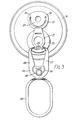
- FIGURE 3 is a plan view showing the first stage of opening of the closure of Fig. 2;
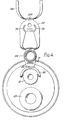
- FIGURE 4 is a plan view showing final stage of opening of the closure;
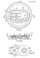
- FIGURE 5A is a plan view of a second embodiment of the closure fitted in a can end;
- FIGURE 5B is a section through the closure on line A-A' in Fig. 5A;
- FIGURE 5C is a sectional plan view taken on line B-B' in Fig. 5;
- FIGURE 6A is a plan view of a third embodiment of the closure fitted in a can end;
- FIGURE 6B is a section through the closure on line A-A' in Fig. 6A;
- FIGURE 7A is a plan view of a fourth embodiment of the closure fitted in a can end;
- FIGURE 7B is a section through the closure on line A-A' in Fig. 7A;
- FIGURE 8A is a plan view of a fifth embodiment of the closure fitted in a can end; and
- FIGURE 8B is a section through the closure on line A-A' in Fig. 8A.
- Figure 1 shows a
can body 1 closed by a canend 2 comprising a domedcentral panel 3 surrounded by a bead 4 connected by achuck wall 5 to a double seam.6 which attaches the can end 2 to thebody 1. - There are two apertures in the
central panel 3, namely a smaller vent aperture near the centre of the domedcentral panel 3 and a larger pouring aperture nearer the bead 4. - The apertures are closed by a
closure 7 moulded from a plastics material such as polypropylene or high density polyethylene (such as grade No. GB 6450 from HOECHST). - The
closure 7 comprises afirst collar portion 8 fitted in an airtight manner into the vent aperture and asecond collar portion 9 fitted in an airtight manner into the pouring aperture. A flexible connectingmember 10 connects a vent plug 11 (sealed to the vent aperture dollar portion 8) to a pouring aperture plug 12 (sealed to the pouring aperture collar portion 9). The flexibility of connectingmember 10 permits each collar portion to tilt, if necessary, to enter its respective aperture and achieve a good flat engagement with thedomed panel 3. The connectingmember 10 is shaped to permit some elastic extension to permit any necessary lateral relative movement between the collars to achieve an easy fit of the collars in the apertures in the panel. - The connecting
member 10 is flexibly connected at 13, e.g. as described below with reference to Fig. 2, to thevent collar portion 8 so that when theplugs collars - In Fig. 1 the
can body 1 is shown to be filled with acarbonated beverage 14 so that internal pressure in theheadspace 15 causes thecentral panel 3 to bulge into domed form. Any increase in this headspace pressure will cause distention of the profile of the central panel. As the connectingmember 10 is flexible, any distorting forces arising from relative movement between thecollars panel 3 being affected. - Referring to Figs. 2A, 28 and 2C, the
closure 17 is a one piece moulding of plastics material comprising a ventaperture collar portion 21 sealed by avent plug 22 and a pouringaperture collar portion 23 sealed by apouring aperture plug 24. A flexible connecting member 25 (best seen in Fig. 2A) connects the two plugs. The flexible connectingmember 25 includes thetop plate 26 ofvent plug 22 and a pair of side members or straps 27, 28 which pass, one to each side of the pouringaperture plug 24, to join the pouring aperture plug at a common junction 29.Arcuate slots 56 separate thestraps top plate 26 of thevent plug 22 except at its side remote from the pouringaperture plug 24. The connectingmember 25 is flexible because it comprises thin plate and straps of plastics material so that any tilting of the axes of the collar portions and of the plugs which are sealed to them will simply bend the connecting member. The connecting member is able to permit lateral relative movement between thecollar portions member 25 further includes atop flange 31 on the pouringaperture plug 24 through which it is flexibly connected to the ventaperture collar portion 21. The flexible connection comprises astep piece 32 extending from the plane offlange 31 to anarcuate yoke 33 which partially surrounds thecollar portion 21. Theyoke 33 joinsstep piece 32 to thecollar portion 21 at twoanchorage points 30 on opposite sides of the collar portion, as is best seen in Fig. 2C. In Figs. 2B and 2C it can be clearly seen that thecollar portions member 25 flexes or extends. - A
pull ring 34 surrounds theplugs flexibfe connecting member 25 at 34A, so that lifting and pulling of the pull ring first tears thevent plug 22 away from the ventaperture collar portion 21 as is shown in Fig. 3. - In Fig. 3 the
pull ring 34 has been pulled clear of the can end 19 so that thepull ring 34, the connectingmember 25 with thevent plug 22, and the ventaperture collar portion 21 are clearly visible. In this first opened position the can has been vented so that the user, may if he wishes, drink by means of a straw. He may also reclose the can when he has had enough. - Referring again to Fig. 3 it will be seen that there is a small
rectangular indent 35 between the extremities ofside members top flange 31 of the pouringaperture plug 24. Thissmall indent 35 encourages the plastics material to fold so that the pulling force delivered frompull ring 34 throughside members aperture plug 24, so avoiding any mechanical disadvantage arising from a more distant application of the tearing force. A like functioningindent 35A is provided where thepull ring 34 joins the connectingmember 25. - Fig. 4 shows the fully opened position in which both plugs 22, 24 have been torn away from their
collar portions aperture collar portion 23. Thecollar portion 23 can be seen to be separate from thecollar portion 21. The captive closure members flexibly connected to the ventaperture collar portion 21 can be seen to comprise theyoke 33, thestep piece 32, theflange 31, the pouringaperture plug 24, the flexible connectingmember 25, thevent plug 22, and thepull ring 34. - The captive closure members may be refolded to reclose the apertures in the collar portions by snap fitting each
plug respective collar portion -
Rectangular slots 55 shown in Figs. 2A and 2B provide access for rods used in the moulding process to hold down split plates used to mould the plug portions. - The
pull ring 34 may, if desired, be held in position before use by means of rupturable side ties 36 (shown in Fig. 2A) in the form of rupturable filaments based on the connectingmember 25. Such ties would provide visible evidence of tampering if broken. Alternativelyfilamentary ties 37 may extend from each collar portion to the underside of the pull ring as is shown in Fig. 2B. Whilst theseties 37 are less visible in use they may be easier to mould than ties 36. - Figs. 5A and 5B show a second embodiment of the closure in which the
collar portions portions member 38 connects directly thepull ring 34, thevent plug 22 and pouringaperture plug 24. The connectingmember 38 is flexible because it is of thin plastics material and extendable, if necessary, by virtue of its cross section. It is flexibly connected to the pouringaperture collar portion 23 by a pair ofstraps top flange 31 of theplug 24 past one side of thevent plug 22 to afold 41 and back past one side of the ventaperture collar portion 21 to join the pouringaperture collar portion 23, as shown in Fig. 5C. - Lifting and pulling on
pull ring 34 first tears the vent plug 22 from itscollar portion 21 and then tears the pouringaperture plug 24 from itscollar portion 23. Thestraps fold 41 to leave both collars clear from pouring and venting. - Figs. 6A and 6B show a third embodiment of the closure in which the
collar portions pull ring 34 connects with the flexible connectingmember 25 which, as in Fig. 2, has side members or straps 27, 28 connecting with thetop flange 31 of the pouringplug 24. However, in Fig. 6B the flexible connection of the connectingmember 25 comprises an extension or step piece depending from one end of thetop flange 31 and joining anarrow bridge 43 which joins the ventaperture collar portion 21 to the pouringaperture collar portion 23. The flexibility necessary to permit tilt of the collar axes is achieved by making thebridge 43 of a cross section and a plan form thin and slender enough so that extension or contraction of theside members member 25 can be accommodated. - The fourth embodiment shown in Figs. 7A and 78 is similar to that of Figs. 6A and 6B, but the extendability of the flexible connecting
member 25 is enhanced by making eachside member - Figs. 8A and 8B show another modified form of the embodiment of Figs. 6A and 68. In Figs. 8A and 8B the pull ring no longer surrounds the closure, but comprises a pair of
first curves top plate 26 of thevent plug 22, eachfirst curve straight side piece side members second curve 46, to constitute a pull ring large enough to grip easily. - The parallel edges of this closure, as defined by the edges of
side members straight side pieces - In all the above embodiments, the freedom of the
collar portions panel 3.
Claims (9)
Applications Claiming Priority (2)
| Application Number | Priority Date | Filing Date | Title |
|---|---|---|---|
| GB848411620A GB8411620D0 (en) | 1984-02-18 | 1984-05-08 | Closures for containers |
| GB8411620 | 1984-05-08 |
Publications (3)
| Publication Number | Publication Date |
|---|---|
| EP0161754A2 true EP0161754A2 (en) | 1985-11-21 |
| EP0161754A3 EP0161754A3 (en) | 1987-08-19 |
| EP0161754B1 EP0161754B1 (en) | 1989-05-24 |
Family
ID=10560588
Family Applications (1)
| Application Number | Title | Priority Date | Filing Date |
|---|---|---|---|
| EP85301838A Expired EP0161754B1 (en) | 1984-05-08 | 1985-03-15 | Closures for containers |
Country Status (14)
| Country | Link |
|---|---|
| US (1) | US4572398A (en) |
| EP (1) | EP0161754B1 (en) |
| JP (1) | JPS60251036A (en) |
| AT (1) | ATE43313T1 (en) |
| AU (1) | AU568012B2 (en) |
| BR (1) | BR8502063A (en) |
| DE (1) | DE3570415D1 (en) |
| DK (1) | DK202485A (en) |
| ES (1) | ES286565Y (en) |
| GB (1) | GB2158423B (en) |
| GR (1) | GR851106B (en) |
| IE (1) | IE56199B1 (en) |
| IN (1) | IN164408B (en) |
| ZA (1) | ZA852106B (en) |
Cited By (3)
| Publication number | Priority date | Publication date | Assignee | Title |
|---|---|---|---|---|
| EP0361019A1 (en) * | 1988-09-08 | 1990-04-04 | Riwisa AG Kunststoffwerke Hägglingen | Container for the receipt of pourable contents |
| EP0819614A1 (en) * | 1996-07-19 | 1998-01-21 | International Paper Emballages Liquides SA - IPEL SA | Opening and closing device for a package, and package with such a device |
| CN101148205B (en) * | 2007-11-05 | 2012-05-02 | 广汉中艺工艺包装有限公司 | False proof device for packing box and its use |
Families Citing this family (19)
| Publication number | Priority date | Publication date | Assignee | Title |
|---|---|---|---|---|
| GB8404320D0 (en) * | 1984-02-18 | 1984-03-21 | Metal Box Plc | Closure for container |
| GB8523262D0 (en) * | 1985-09-20 | 1985-10-23 | Metal Box Plc | Metal can end |
| US4705186A (en) * | 1986-11-19 | 1987-11-10 | The Coca-Cola Company | Can end assembly |
| GB8815486D0 (en) * | 1988-06-29 | 1988-08-03 | Grace W R & Co | Container closures & materials for use in these |
| US5011037A (en) * | 1989-11-30 | 1991-04-30 | Adolph Coors Company | Container end member |
| US5285919A (en) * | 1992-12-30 | 1994-02-15 | Donald Recchia | Beverage container with air access for direct drinking |
| US5688544A (en) * | 1995-04-18 | 1997-11-18 | Kraft Foods, Inc. | Easy opening ventable closure for sealed particulate product package |
| US6399170B1 (en) | 1997-12-24 | 2002-06-04 | Owens-Illinois Closure Inc. | Plastic closure with compression molded barrier liner |
| US6371318B1 (en) | 1997-12-24 | 2002-04-16 | Owens-Illinois Closure Inc. | Plastic closure with compression molded sealing/barrier liner |
| DK1110873T3 (en) | 1999-12-14 | 2007-11-05 | Tetra Laval Holdings & Finance | Packaging provided with an opening device |
| ITRM20010045U1 (en) * | 2001-03-12 | 2002-09-12 | Fiorentini Graziella | REFINEMENTS IN CANS FOR CARBONATED AND NON-CARCULATED BEVERAGES, AND IN THE RELATED CLOSING SYSTEMS. |
| US6626314B1 (en) | 2001-03-13 | 2003-09-30 | Rexam Beverage Can Company | Resealable closure for beverage container |
| ATE259327T1 (en) * | 2001-04-02 | 2004-02-15 | Rexam Beverage Can Co | RESEALABLE CLOSURE FOR THE OPEN END OF A DRINK CONTAINER |
| US6889861B2 (en) * | 2002-09-04 | 2005-05-10 | Richard Arcati | Beverage can |
| KR100387622B1 (en) * | 2002-10-18 | 2003-06-18 | Bo Yeoun Hwang | Can opening apparatus |
| GB2429009A (en) * | 2005-08-09 | 2007-02-14 | Jason Andrew Titton | Venting drinks can for effervescent liquids |
| NL2007748C2 (en) * | 2011-11-08 | 2013-05-13 | Corstiaan Johannes Goolen | TERMINAL ELEMENT AND HOLDER PROVIDED WITH SUCH TERMINAL ELEMENT. |
| US9884701B2 (en) | 2014-06-23 | 2018-02-06 | Rexam Beverage Can Company | Ecology can end with pressure equalization port |
| EP3670373B1 (en) | 2018-12-17 | 2021-05-12 | RE-LID Engineering AG | Closure system for drink cans |
Citations (2)
| Publication number | Priority date | Publication date | Assignee | Title |
|---|---|---|---|---|
| DE1432136A1 (en) * | 1964-05-20 | 1969-01-23 | Continental Can Co | Closure for containers, especially for cans |
| DE2257512A1 (en) * | 1971-11-23 | 1973-05-30 | Nat Can Corp | RE-SEALABLE CONTAINER |
Family Cites Families (4)
| Publication number | Priority date | Publication date | Assignee | Title |
|---|---|---|---|---|
| US3756448A (en) * | 1971-02-17 | 1973-09-04 | Continental Can Co | Easy opening structure |
| US4344545A (en) * | 1981-04-13 | 1982-08-17 | The Continental Group, Inc. | Pilferproof closure with mechanical interlock |
| US4431110A (en) * | 1982-11-09 | 1984-02-14 | Continental Can Company, Inc. | Child resistant tamper indicating closure |
| GB8404320D0 (en) * | 1984-02-18 | 1984-03-21 | Metal Box Plc | Closure for container |
-
1985
- 1985-03-15 EP EP85301838A patent/EP0161754B1/en not_active Expired
- 1985-03-15 DE DE8585301838T patent/DE3570415D1/en not_active Expired
- 1985-03-15 AT AT85301838T patent/ATE43313T1/en not_active IP Right Cessation
- 1985-03-15 GB GB08506746A patent/GB2158423B/en not_active Expired
- 1985-03-20 ZA ZA852106A patent/ZA852106B/en unknown
- 1985-03-21 AU AU40205/85A patent/AU568012B2/en not_active Ceased
- 1985-03-21 IE IE721/85A patent/IE56199B1/en unknown
- 1985-03-22 US US06/714,825 patent/US4572398A/en not_active Expired - Fee Related
- 1985-04-01 IN IN253/MAS/85A patent/IN164408B/en unknown
- 1985-04-30 BR BR8502063A patent/BR8502063A/en unknown
- 1985-04-30 JP JP60093514A patent/JPS60251036A/en active Pending
- 1985-05-07 GR GR851106A patent/GR851106B/el unknown
- 1985-05-07 DK DK202485A patent/DK202485A/en not_active Application Discontinuation
- 1985-05-07 ES ES1985286565U patent/ES286565Y/en not_active Expired
Patent Citations (2)
| Publication number | Priority date | Publication date | Assignee | Title |
|---|---|---|---|---|
| DE1432136A1 (en) * | 1964-05-20 | 1969-01-23 | Continental Can Co | Closure for containers, especially for cans |
| DE2257512A1 (en) * | 1971-11-23 | 1973-05-30 | Nat Can Corp | RE-SEALABLE CONTAINER |
Cited By (6)
| Publication number | Priority date | Publication date | Assignee | Title |
|---|---|---|---|---|
| EP0361019A1 (en) * | 1988-09-08 | 1990-04-04 | Riwisa AG Kunststoffwerke Hägglingen | Container for the receipt of pourable contents |
| EP0819614A1 (en) * | 1996-07-19 | 1998-01-21 | International Paper Emballages Liquides SA - IPEL SA | Opening and closing device for a package, and package with such a device |
| FR2751303A1 (en) * | 1996-07-19 | 1998-01-23 | Int Paper Emballages Liquides | DEVICE FOR OPENING AND CLOSING A PACKAGING, AND PACKAGING PROVIDED WITH SUCH A DEVICE |
| US5947316A (en) * | 1996-07-19 | 1999-09-07 | International Paper Emballages Liquides Sa - Ipel Sa | Device for opening and closing a package, and package provided with such a device |
| CN1069283C (en) * | 1996-07-19 | 2001-08-08 | 国际液体纸包装材料有限公司 | Device for opening and closing package, and package provided with such device |
| CN101148205B (en) * | 2007-11-05 | 2012-05-02 | 广汉中艺工艺包装有限公司 | False proof device for packing box and its use |
Also Published As
| Publication number | Publication date |
|---|---|
| AU568012B2 (en) | 1987-12-10 |
| DK202485D0 (en) | 1985-05-07 |
| GB2158423A (en) | 1985-11-13 |
| DE3570415D1 (en) | 1989-06-29 |
| GB8506746D0 (en) | 1985-04-17 |
| EP0161754B1 (en) | 1989-05-24 |
| IE850721L (en) | 1985-11-08 |
| GB2158423B (en) | 1987-06-24 |
| BR8502063A (en) | 1985-12-31 |
| ES286565U (en) | 1986-11-01 |
| GR851106B (en) | 1985-11-25 |
| US4572398A (en) | 1986-02-25 |
| EP0161754A3 (en) | 1987-08-19 |
| JPS60251036A (en) | 1985-12-11 |
| IE56199B1 (en) | 1991-05-08 |
| AU4020585A (en) | 1985-11-14 |
| ES286565Y (en) | 1987-07-16 |
| ATE43313T1 (en) | 1989-06-15 |
| ZA852106B (en) | 1986-11-26 |
| DK202485A (en) | 1985-11-09 |
| IN164408B (en) | 1989-03-11 |
Similar Documents
| Publication | Publication Date | Title |
|---|---|---|
| US4572398A (en) | Closures for containers | |
| EP0153068B1 (en) | Closure for a container | |
| EP0220820B1 (en) | Metal can end with plastics closure | |
| US6231491B1 (en) | Method for transporting fitment | |
| US5104008A (en) | Resealable bottle cap with push-pull closure | |
| US5758793A (en) | Reclosable top for can | |
| US4407423A (en) | Detachable resealable closure | |
| US20010015355A1 (en) | Fitment having removable membrane | |
| CZ217994A3 (en) | Beverage container | |
| US5823377A (en) | Screw cap having a tamper resistant connection to a plastic container | |
| US4360121A (en) | Easy-open lid closure arrangement | |
| US4711380A (en) | Tamper-evident seal for a toggle-type dispensing valve | |
| MXPA04003399A (en) | Closure including cap and fitment having gripping member. | |
| US4318494A (en) | Easy opening container with vent means | |
| US5855288A (en) | Resealable closure | |
| US4911323A (en) | Resealable container closure | |
| US4227617A (en) | Container closure | |
| KR20030051715A (en) | Container-closure arrangement | |
| US4073403A (en) | Push-in can top | |
| US3556336A (en) | Tear-off container closure | |
| US4220249A (en) | Closing arrangement for packing containers | |
| US4289252A (en) | Hermetically sealed container | |
| EP1220796B1 (en) | Tamperproof lid and container | |
| US2831600A (en) | Detachable closure | |
| US3235121A (en) | Container closure structure |
Legal Events
| Date | Code | Title | Description |
|---|---|---|---|
| PUAI | Public reference made under article 153(3) epc to a published international application that has entered the european phase |
Free format text: ORIGINAL CODE: 0009012 |
|
| 17P | Request for examination filed |
Effective date: 19850902 |
|
| AK | Designated contracting states |
Designated state(s): AT BE CH DE FR GB IT LI LU NL SE |
|
| PUAL | Search report despatched |
Free format text: ORIGINAL CODE: 0009013 |
|
| AK | Designated contracting states |
Kind code of ref document: A3 Designated state(s): AT BE CH DE FR GB IT LI LU NL SE |
|
| 17Q | First examination report despatched |
Effective date: 19880310 |
|
| RAP1 | Party data changed (applicant data changed or rights of an application transferred) |
Owner name: MB GROUP PLC |
|
| GRAA | (expected) grant |
Free format text: ORIGINAL CODE: 0009210 |
|
| AK | Designated contracting states |
Kind code of ref document: B1 Designated state(s): AT BE CH DE FR IT LI LU NL SE |
|
| REF | Corresponds to: |
Ref document number: 43313 Country of ref document: AT Date of ref document: 19890615 Kind code of ref document: T |
|
| ITF | It: translation for a ep patent filed |
Owner name: JACOBACCI & PERANI S.P.A. |
|
| REF | Corresponds to: |
Ref document number: 3570415 Country of ref document: DE Date of ref document: 19890629 |
|
| ET | Fr: translation filed | ||
| PGFP | Annual fee paid to national office [announced via postgrant information from national office to epo] |
Ref country code: FR Payment date: 19900202 Year of fee payment: 6 |
|
| PGFP | Annual fee paid to national office [announced via postgrant information from national office to epo] |
Ref country code: AT Payment date: 19900207 Year of fee payment: 6 |
|
| PGFP | Annual fee paid to national office [announced via postgrant information from national office to epo] |
Ref country code: SE Payment date: 19900221 Year of fee payment: 6 |
|
| PGFP | Annual fee paid to national office [announced via postgrant information from national office to epo] |
Ref country code: CH Payment date: 19900222 Year of fee payment: 6 |
|
| PGFP | Annual fee paid to national office [announced via postgrant information from national office to epo] |
Ref country code: BE Payment date: 19900226 Year of fee payment: 6 |
|
| PGFP | Annual fee paid to national office [announced via postgrant information from national office to epo] |
Ref country code: LU Payment date: 19900227 Year of fee payment: 6 Ref country code: DE Payment date: 19900227 Year of fee payment: 6 |
|
| ITTA | It: last paid annual fee | ||
| PG25 | Lapsed in a contracting state [announced via postgrant information from national office to epo] |
Ref country code: LU Free format text: LAPSE BECAUSE OF NON-PAYMENT OF DUE FEES Effective date: 19900331 |
|
| PGFP | Annual fee paid to national office [announced via postgrant information from national office to epo] |
Ref country code: NL Payment date: 19900331 Year of fee payment: 6 |
|
| PLBE | No opposition filed within time limit |
Free format text: ORIGINAL CODE: 0009261 |
|
| STAA | Information on the status of an ep patent application or granted ep patent |
Free format text: STATUS: NO OPPOSITION FILED WITHIN TIME LIMIT |
|
| 26N | No opposition filed | ||
| PG25 | Lapsed in a contracting state [announced via postgrant information from national office to epo] |
Ref country code: AT Effective date: 19910315 |
|
| PG25 | Lapsed in a contracting state [announced via postgrant information from national office to epo] |
Ref country code: SE Effective date: 19910316 |
|
| PG25 | Lapsed in a contracting state [announced via postgrant information from national office to epo] |
Ref country code: LI Effective date: 19910331 Ref country code: CH Effective date: 19910331 Ref country code: BE Effective date: 19910331 |
|
| BERE | Be: lapsed |
Owner name: MB GROUP P.L.C. Effective date: 19910331 |
|
| PG25 | Lapsed in a contracting state [announced via postgrant information from national office to epo] |
Ref country code: NL Effective date: 19911001 |
|
| NLV4 | Nl: lapsed or anulled due to non-payment of the annual fee | ||
| PG25 | Lapsed in a contracting state [announced via postgrant information from national office to epo] |
Ref country code: FR Effective date: 19911129 |
|
| REG | Reference to a national code |
Ref country code: CH Ref legal event code: PL |
|
| PG25 | Lapsed in a contracting state [announced via postgrant information from national office to epo] |
Ref country code: DE Effective date: 19920101 |
|
| REG | Reference to a national code |
Ref country code: FR Ref legal event code: ST |
|
| EUG | Se: european patent has lapsed |
Ref document number: 85301838.0 Effective date: 19911009 |