EP0161685A2 - Construction of door frame in motor vehicle - Google Patents
Construction of door frame in motor vehicle Download PDFInfo
- Publication number
- EP0161685A2 EP0161685A2 EP85106022A EP85106022A EP0161685A2 EP 0161685 A2 EP0161685 A2 EP 0161685A2 EP 85106022 A EP85106022 A EP 85106022A EP 85106022 A EP85106022 A EP 85106022A EP 0161685 A2 EP0161685 A2 EP 0161685A2
- Authority
- EP
- European Patent Office
- Prior art keywords
- door frame
- glass
- side portion
- door
- door glass
- Prior art date
- Legal status (The legal status is an assumption and is not a legal conclusion. Google has not performed a legal analysis and makes no representation as to the accuracy of the status listed.)
- Granted
Links
Images


Classifications
-
- B—PERFORMING OPERATIONS; TRANSPORTING
- B60—VEHICLES IN GENERAL
- B60J—WINDOWS, WINDSCREENS, NON-FIXED ROOFS, DOORS, OR SIMILAR DEVICES FOR VEHICLES; REMOVABLE EXTERNAL PROTECTIVE COVERINGS SPECIALLY ADAPTED FOR VEHICLES
- B60J5/00—Doors
- B60J5/04—Doors arranged at the vehicle sides
- B60J5/0401—Upper door structure
- B60J5/0402—Upper door structure window frame details, including sash guides and glass runs
-
- B—PERFORMING OPERATIONS; TRANSPORTING
- B60—VEHICLES IN GENERAL
- B60J—WINDOWS, WINDSCREENS, NON-FIXED ROOFS, DOORS, OR SIMILAR DEVICES FOR VEHICLES; REMOVABLE EXTERNAL PROTECTIVE COVERINGS SPECIALLY ADAPTED FOR VEHICLES
- B60J10/00—Sealing arrangements
- B60J10/20—Sealing arrangements characterised by the shape
- B60J10/24—Sealing arrangements characterised by the shape having tubular parts
-
- B—PERFORMING OPERATIONS; TRANSPORTING
- B60—VEHICLES IN GENERAL
- B60J—WINDOWS, WINDSCREENS, NON-FIXED ROOFS, DOORS, OR SIMILAR DEVICES FOR VEHICLES; REMOVABLE EXTERNAL PROTECTIVE COVERINGS SPECIALLY ADAPTED FOR VEHICLES
- B60J10/00—Sealing arrangements
- B60J10/30—Sealing arrangements characterised by the fastening means
-
- B—PERFORMING OPERATIONS; TRANSPORTING
- B60—VEHICLES IN GENERAL
- B60J—WINDOWS, WINDSCREENS, NON-FIXED ROOFS, DOORS, OR SIMILAR DEVICES FOR VEHICLES; REMOVABLE EXTERNAL PROTECTIVE COVERINGS SPECIALLY ADAPTED FOR VEHICLES
- B60J10/00—Sealing arrangements
- B60J10/70—Sealing arrangements specially adapted for windows or windscreens
- B60J10/74—Sealing arrangements specially adapted for windows or windscreens for sliding window panes, e.g. sash guides
- B60J10/79—Sealing arrangements specially adapted for windows or windscreens for sliding window panes, e.g. sash guides for flush-glass windows, i.e. for windows flush with the vehicle body or the window frame
Definitions
- This invention relates to a construction of a door frame in a motor vehicle, and more particularly, improvement in a door frame in a motor vehicle, including:
- a door frame having a glass run 3 being of a U-shape in cross section, being in relatively sliding contact with the inner and outer surfaces of a forward or rear end edge 1A of the door glass 1 in the direction of opening or closing direction of the door glass 1, guiding the door glass 1 in the direction of opening or closing direction thereof and sealing a space formed between the door glass 1 and the door frame 2.
- the above-described construction of the door frame can guide the door glass 1 in the sealed condition and reliably prevent the door glass 1 from being pushed outwardly due to a difference in pressure between the interior and the exterior of the compartment during running of the motor veichle at high speed.
- the above-described construction of the door frame presents such a disadvantage that a leg 2A of the door frame 2 is extended further outside of an outer side portion 3A of the glass run 3, which portion 3A is in contact with the outer surface of the door glass 1, whereby the glass run 3 should be pushed in from outside, and, because of this, a difference h in stage between the outer surface of the door glass 1 and the door frame 2 becomes large.
- the present invetnion contemplates that, in a construction of a door frame in a motor vehicle, including: a door frame; a glass run having an outer side portion and an inner side portion in sliding contact with an outer surface and an inner surface of a side end edge of a door glass, respectively, and a bottom portion connecting the outer and inner side portions to each other, for vertically slidably guiding the door glass and sealing a space formed between the door glass and the door frame; and a core plate member for reinforcing the glass run; the outer side portion is disposed such that the outer side portion is exposed to the outside of the vehicle, with respect to the door glass, the outer side portion is located at a position where the door glass is shifted toward the outer side portion between the outer side portion and the inner side portion, and the outer surface of the door glass is substantially flush with the outer surface of the door frame.
- the present invention contemplates that the core plate member extends along the outer surface of the door glass on the outboard side of the outer side portion of the glass run and exposed to be outside.
- the present invention contemplates that the inner side portion of the glass run, the core plate member and the door frame, at the portions which are opposed to the inner surface of a side end edge of the door glass, are inclined in a manner to be gradually separated from the inner surface of the side end edge toward the interior of a compartment and the center of the door glass, the inclined portions of the inner side portion and of the core plate member are tightendly fixed to an inclined portion of the inner side portion at a position on the side of the compartment of the side end edge, and an inner fin portion is formed which comes into sealingly sliding contact with the inner surface of the side end edge from the inner side portion and covering the tightenedly fixing portion from outside.
- the present invention contemplates that the door frame is curved along the forward or rear end edge of the door glass into a generally crank-shape, the glass run is formed into a U-shape in cross section an tightenedly fixed at the bottom portion thereof to the door frame through a bolt-nut means, and a projection is projected and extended from the bottom portion of the glass run preventing the forward or rear end edge of the door glass from directly contacting the bolt-nut means.
- a door glass weather strip is mounted to a tansverse member and an oblique member both of which are disposed at the upper side portion of the door frame and having a top end sealing projection adapted to be clamped between the top end of the door glass and the door frame to seal a space formed therebetween when the door glass is fully closed and an inner side sealing projection being in contact with the inner surface of the door glass.
- a the glass run is formed of a relatively soft resin including rubber and synthetic resin and manufactured integrally with the metallic core plate member.
- the outer surface of the outer side portion of the glass run is not covered by the door frame, the guide of the outer surface of the door glass is provided only by the outer side portion, and the door glass is displaced toward the outer side portion within the glass run and substantially flush with the outer surface of the door frame, so that the door glass and the door frame can be flush with each other.
- a glass run 20 having an outer side portion 14 and an inner side portion 16 in sliding contact with an outer surface 12B and an inner surface 12C of a forward or rear end edge 12A of a door glass 12, respectively, and a bottom portion 18 connecting the outer and inner side portion 14 and 16 to each other, for vertically slidably guiding the door glass 12 and sealing a space formed between the door glass 12 and the door frame 10; and a core plate member 22 for reinforcing the glass run 20;
- the outer side portion 14 is disposed such that the outer side portion 14 is exposed to the outside of the vehicle, with respect to the door glass 12, the outer side portion 14 is located at a position where the door glass 12 is shifted toward the outer side portion 14 between the outer side portion 14 and the inner side portion 16, and the outer surface 12B of the door glass 12 is substantially flush with the outer surfacae l0A of the door frame 10.
- the inner side portion 16 of the glass run 20, the core plate member 22 and the door frame 10, at the portions which are opposed to the inner surface of a forward or rear side end edge 12A of the door glass 12, are inclined in a manner to be gradually separated from the inner surface of the forward or rear end edge 12A toward the interior of a compartment 24 and the center of the door glass 12, the inclined portions 16A and 22A of the inner side portion 16 and of the core plate member 22 are tightenedly fixed through a tapping screw 26 to an inclinded portion 10B of the door frame 10 at a position on the side of the compartment 24 of the forward or rear end edge 12A, and an inner fin portion 16B is formed which comes into sealingly sliding contact with the inner surface 12C of the forward or rear end edge 12A from the inner side portion 16 and covering a head of the tapping screw 26 from outside.
- an outer fin portion formed on the forward end of the outer side portion 14 and being in sealingly sliding contact with the outer surface 12B of the forward or rear end edge 12A of the door glass 12.
- the glass run 20 including the outer fin portion 14A and the inner fin portion 16B is formed of a relatively soft resin including rubber and synthetic resin and manufactured integrally with the metallic core plate member 22 by extrusion, rolling or injection molding.
- denoted at 28 is a projection smoothly continued to the outer surface 10A of the door frame 10 and integrally formed with the glass run 20 in a manner to seal a space formed between the glass run 20 and the door frame 10.
- Fig. 3 shows sections of a transverse member and an oblique member, both of which are disposed at the upper side portion of the door frame 10.
- a door glass weather strip 30 having a top end sealing projection 30A adapted to be clamped between the top end of the door glass 12 and the door frame to seal a space formed therebetween when the door glass 12 is fully closed and an inner side sealing projection 30B being in contact with the inner surface of the door glass.
- the outer surface 10A of the door frame 10 is substantially flush with the outer surface 12B of the door glass 12.
- the door glass 12 is substantially flush with the outer surface l0A of the door frame 10, with respect to the door glass 12, the outer side portion 14 of the glass run 20 is shifted closer to the outer surface 12B of the door glass 12, and the outer side portion 14 of the door glass run 20 is in sealingly sliding contact with the outer surface 12B of the door glass 12, so that the door glass 12 can be reliably held and guided without permitting the glass run 20 and the core plate member 22 reinforcing the glass run 20 to greatly project outwardly.
- the core plate member 22 is previously assembled in the glass run, so that improvements can be effected in reduction of the number of assembling man-hour, the dimensional accuracy in the direction of door glass thickness and the accuracy of assembling with the door glass 12.
- the inclined portions 16A, 22A and 10B are formed on the inner side portion 16, core plate member 22 and door frame 10, respectively, these inclined portions are tightenedly fixed and integrally connected to one another by the tapping screw 26 and the outer surface of the tapping screw 26 is covered by the inner fin portion 16B integrally extended from the inner side portion 16, so that the operation of assembling the glass run 20 to the door frame 10 can be facilitated and the aesthetic appearance thereof can be improved.
- the core plate member 22 in the first embodiment is extended along the outer surface 12B of the door glass 12 on the outboard side of the outer side portion 14 of the glass run 20 and exposed to the outside.
- the core plate member 22 is formed of a bright material such as stainless steel or aluminum so as to additionally function as a decoration.
- the door frame 10 is curved along the forward or rear end edge 12A of the door glass 12 into a generally crank-shape, while the glass run 20 is formed into a U-shape in cross section an tightenedly fixed at the bottom portion 18 thereof to the door frame 10 through a bolt 32A and a nut 32B.
- the inclined portion 22A in the first embodiment is dispensed with, and the core plate member 22 is constituted only by the outer side portion 22B and the bottom portion 22C.
- Fig. 4 designated at 18A is a projection projected and extended from the bottom portion 18 of the glass run 20 to thereby prevent the forward or rear end edge 12A of the door glass 20 from directly contacting the bolt 32A.
- a second outer fin portion 14B contacting the outer surface 12B of the forward or rear end edge 12A of the door glass 12 is formed at a positon opposite to the outer fin portion 14A provided on the forward end of the outer side portion 14 of the glass run 20.
- this second embdiment is applied to the case where the door frame 10 has little allowance in the direction of the door thickness. Additionally, the second embodiment is applicable to the case where it is desired to give luster to the frame for the design effect.
- the outer and inner side portions 14 and 16 of the glass run 20 come into sliding contact with the outer and inner surfaces 12B and 12C of the forward or rear end edge 12a of the door glass 12 through the fin portions continuously and integrally fromed on the forward ends of the outer and inner side portions, respectively.
- the present invention need not necessarily be limited to this, and the outer and inner side portions 14 and 16 may directly contact the door glass 12 without providing these fin portions.
- the door frame for guiding the forward or rear end edge 12A of the door glass 12.
- the description may be made on any one if it can guide the side end edge.
- the invention is applied only to the rear end edge, while, the forward end edge may have the conventional construction as shown in Fig. 5.
Landscapes
- Engineering & Computer Science (AREA)
- Mechanical Engineering (AREA)
- Seal Device For Vehicle (AREA)
- Window Of Vehicle (AREA)
Abstract
Description
- This invention relates to a construction of a door frame in a motor vehicle, and more particularly, improvement in a door frame in a motor vehicle, including:
- a door frame;
- a glass run having an outer side portion and an inner side portion, which are in sliding contact with an outer surface and an inner surface of a side end edge of a door glass, respectively, and a bottom portion connecting these outer and inner side portions to each other, for vertically slidably guiding the door glass and sealing a space formed between the door glass and the door frame; and
- a core plate member for reinforcing the glass run.
- As shown in Fig. 5 for example, in order to hold a
door glass 1 in a motor vehicle and guide the same in a direction of opening or closing of thedoor glass 1, there is a construction of a door frame having aglass run 3 being of a U-shape in cross section, being in relatively sliding contact with the inner and outer surfaces of a forward orrear end edge 1A of thedoor glass 1 in the direction of opening or closing direction of thedoor glass 1, guiding thedoor glass 1 in the direction of opening or closing direction thereof and sealing a space formed between thedoor glass 1 and thedoor frame 2. - The above-described construction of the door frame can guide the
door glass 1 in the sealed condition and reliably prevent thedoor glass 1 from being pushed outwardly due to a difference in pressure between the interior and the exterior of the compartment during running of the motor veichle at high speed. - However, the above-described construction of the door frame presents such a disadvantage that a
leg 2A of thedoor frame 2 is extended further outside of anouter side portion 3A of theglass run 3, whichportion 3A is in contact with the outer surface of thedoor glass 1, whereby theglass run 3 should be pushed in from outside, and, because of this, a difference h in stage between the outer surface of thedoor glass 1 and thedoor frame 2 becomes large. - Such a large difference in stage between the outer surface of the
door glass 1 and thedoor frame 2 presents the disadvantage that the air resistance is increased and the so-called wind whistle is increased during running of the motor vehicle at high speed. - To obviate the above-described disadvantage, as described in West German Patnt No. 2,809,721 for example, there is proposed a construction of a door frame in a motor vehicle, wherein a slider is mounted to the forward or rear end edge of the door glass in a manner to be shifted toward the interior of the compartment, and this slider is guided by a guide integrally with the door frame and opposed to the slider and disposed inside the door glass in a manner to be slidable in the direction of opening or closing of the door glass and be restrained in the direction of the thickness of the door glass.
- Furthermore, as shown in European Patent Application Laid-Open No. 0,040,588, there is proposed another construction of the door frame in a motor vehicle, wherein an intermediate support member (slider) being of a generally crank-shape is mounted to a forward or rear end edge of the door glass such that the forward end of intermediate support member is shifted into the compartment from the door glass and projected in parallel to the door glass, and the forward end of this intermediate support member is guided by the glass run in the direction of opening or closing of the door glass.
- Either one of these constructions presents the disadvantage that the outer surface of the door glass is made substantially flush with the outer surface of the door frame, so taht contribution may be made to the flushness of the vehicle body, however, a slider or a guide is needed, thus raising the manufacturing cost or narrowing the opening area of the door glass by the presence of the slider.
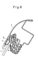
- As against the above, as described in Japanese Utility Model Laid-Open (Kokai) No. 65117/1983 (Refer to Fig. 6), there is disclosed a construction wherein an
outer side portion 3A of aglass run 3 is covered bycore plate member 7 for reinforcing thisglass run 3 and an outer surface of thecore plate member 7 is directly exposed to the outside of the vehicle body without adoor frame 2 being extended outwardly of thecore plate member 7. - In this case, since the member on the door frame's side is not doubly provided outwardly of the
core plate member 7, the difference in stage between thedoor glass 1 and thedoor frame 2 is reduced by a value of thickness of thedoor frame 2 as compared with the case of Fig. 5. - However, in this cases also, relatively large difference h in stage still remains between the outer surfaces of the
core plate member 7 and thedoor glass 1. - It is therefore the primary object of this invention to provide a construction of a door frame in a motor vehicle, wherein a difference in stage between the glass and the door frame can be reduced by a simplified arrangement without the use of a member such as a slider.
- To this end, the present invetnion contemplates that, in a construction of a door frame in a motor vehicle, including: a door frame; a glass run having an outer side portion and an inner side portion in sliding contact with an outer surface and an inner surface of a side end edge of a door glass, respectively, and a bottom portion connecting the outer and inner side portions to each other, for vertically slidably guiding the door glass and sealing a space formed between the door glass and the door frame; and a core plate member for reinforcing the glass run; the outer side portion is disposed such that the outer side portion is exposed to the outside of the vehicle, with respect to the door glass, the outer side portion is located at a position where the door glass is shifted toward the outer side portion between the outer side portion and the inner side portion, and the outer surface of the door glass is substantially flush with the outer surface of the door frame.
- To the above end, the present invention contemplates that the core plate member extends along the outer surface of the door glass on the outboard side of the outer side portion of the glass run and exposed to be outside.
- To the above end, the present invention contemplates that the inner side portion of the glass run, the core plate member and the door frame, at the portions which are opposed to the inner surface of a side end edge of the door glass, are inclined in a manner to be gradually separated from the inner surface of the side end edge toward the interior of a compartment and the center of the door glass, the inclined portions of the inner side portion and of the core plate member are tightendly fixed to an inclined portion of the inner side portion at a position on the side of the compartment of the side end edge, and an inner fin portion is formed which comes into sealingly sliding contact with the inner surface of the side end edge from the inner side portion and covering the tightenedly fixing portion from outside.
- To the above end, the present invention contemplates that the door frame is curved along the forward or rear end edge of the door glass into a generally crank-shape, the glass run is formed into a U-shape in cross section an tightenedly fixed at the bottom portion thereof to the door frame through a bolt-nut means, and a projection is projected and extended from the bottom portion of the glass run preventing the forward or rear end edge of the door glass from directly contacting the bolt-nut means.
- To the above end, the present invention contemplates that a door glass weather strip is mounted to a tansverse member and an oblique member both of which are disposed at the upper side portion of the door frame and having a top end sealing projection adapted to be clamped between the top end of the door glass and the door frame to seal a space formed therebetween when the door glass is fully closed and an inner side sealing projection being in contact with the inner surface of the door glass.
- To the above end, the present invention contemplates that a the glass run is formed of a relatively soft resin including rubber and synthetic resin and manufactured integrally with the metallic core plate member.
- According to the present invention, the outer surface of the outer side portion of the glass run is not covered by the door frame, the guide of the outer surface of the door glass is provided only by the outer side portion, and the door glass is displaced toward the outer side portion within the glass run and substantially flush with the outer surface of the door frame, so that the door glass and the door frame can be flush with each other.
-
- Fig. 1 is a front view showing one embodiment of the construction of the door frame in a motor vehicle;
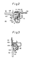
- Figs. 2 and 3 are enlarged sectional views taken along the lines II - II and III - III in Fig. 1, respectively.
- Fig. 4 is a enlarged sectional view showing a second embodiment of the present invention, of a portion corresponding to the line II - II in Fig. 1;
- Fig. 5 is a sectional view showing a conventional door frame construction in motor vehicle, similar to Fig. 2; and
- Fig. 6 is a sectional view showing another conventional door frame construction in a motor vehicle, similar to Fig. 2.
- Description will hereunder be given of the embodiment of the present invention with reference to the drawings.
- As shown in Figs. 1 to 3, according to the present invention, in a construction of a door frame in a motor vehicle, including: a door frame 10: a
glass run 20 having anouter side portion 14 and aninner side portion 16 in sliding contact with anouter surface 12B and aninner surface 12C of a forward orrear end edge 12A of adoor glass 12, respectively, and abottom portion 18 connecting the outer andinner side portion door glass 12 and sealing a space formed between thedoor glass 12 and thedoor frame 10; and acore plate member 22 for reinforcing theglass run 20; theouter side portion 14 is disposed such that theouter side portion 14 is exposed to the outside of the vehicle, with respect to thedoor glass 12, theouter side portion 14 is located at a position where thedoor glass 12 is shifted toward theouter side portion 14 between theouter side portion 14 and theinner side portion 16, and theouter surface 12B of thedoor glass 12 is substantially flush with the outer surfacae l0A of thedoor frame 10. - The
inner side portion 16 of the glass run 20, thecore plate member 22 and thedoor frame 10, at the portions which are opposed to the inner surface of a forward or rearside end edge 12A of thedoor glass 12, are inclined in a manner to be gradually separated from the inner surface of the forward orrear end edge 12A toward the interior of acompartment 24 and the center of thedoor glass 12, theinclined portions inner side portion 16 and of thecore plate member 22 are tightenedly fixed through a tappingscrew 26 to aninclinded portion 10B of thedoor frame 10 at a position on the side of thecompartment 24 of the forward orrear end edge 12A, and aninner fin portion 16B is formed which comes into sealingly sliding contact with theinner surface 12C of the forward orrear end edge 12A from theinner side portion 16 and covering a head of the tappingscrew 26 from outside. - In the drawing, designated at 14A is an outer fin portion formed on the forward end of the
outer side portion 14 and being in sealingly sliding contact with theouter surface 12B of the forward orrear end edge 12A of thedoor glass 12. - The
glass run 20 including theouter fin portion 14A and theinner fin portion 16B is formed of a relatively soft resin including rubber and synthetic resin and manufactured integrally with the metalliccore plate member 22 by extrusion, rolling or injection molding. - In the drawing, denoted at 28 is a projection smoothly continued to the
outer surface 10A of thedoor frame 10 and integrally formed with the glass run 20 in a manner to seal a space formed between theglass run 20 and thedoor frame 10. - Fig. 3 shows sections of a transverse member and an oblique member, both of which are disposed at the upper side portion of the
door frame 10. Mounted to thedoor frame 10 is a doorglass weather strip 30 having a topend sealing projection 30A adapted to be clamped between the top end of thedoor glass 12 and the door frame to seal a space formed therebetween when thedoor glass 12 is fully closed and an innerside sealing projection 30B being in contact with the inner surface of the door glass. Even in the upper side portion of thedoor frame 10, theouter surface 10A of thedoor frame 10 is substantially flush with theouter surface 12B of thedoor glass 12. - In this embodiment, the
door glass 12 is substantially flush with the outer surface l0A of thedoor frame 10, with respect to thedoor glass 12, theouter side portion 14 of theglass run 20 is shifted closer to theouter surface 12B of thedoor glass 12, and theouter side portion 14 of thedoor glass run 20 is in sealingly sliding contact with theouter surface 12B of thedoor glass 12, so that thedoor glass 12 can be reliably held and guided without permitting the glass run 20 and thecore plate member 22 reinforcing theglass run 20 to greatly project outwardly. - Particularly, in this embodiment, as compared with the aforesaid Japanese Utility Model Laid-Open (Kokai) No. 65117/1983, the
core plate member 22 is previously assembled in the glass run, so that improvements can be effected in reduction of the number of assembling man-hour, the dimensional accuracy in the direction of door glass thickness and the accuracy of assembling with thedoor glass 12. - Furthermore, in the above embodiment, the
inclined portions inner side portion 16,core plate member 22 anddoor frame 10, respectively, these inclined portions are tightenedly fixed and integrally connected to one another by the tappingscrew 26 and the outer surface of the tappingscrew 26 is covered by the innerfin portion 16B integrally extended from theinner side portion 16, so that the operation of assembling the glass run 20 to thedoor frame 10 can be facilitated and the aesthetic appearance thereof can be improved. - Description will hereunder be given of the second embodiment of the present invention with reference to Fig. 4.
- In this second embodiment, the
core plate member 22 in the first embodiment is extended along theouter surface 12B of thedoor glass 12 on the outboard side of theouter side portion 14 of the glass run 20 and exposed to the outside. - In this case, the
core plate member 22 is formed of a bright material such as stainless steel or aluminum so as to additionally function as a decoration. - Further, in this second embodiment, the
door frame 10 is curved along the forward orrear end edge 12A of thedoor glass 12 into a generally crank-shape, while theglass run 20 is formed into a U-shape in cross section an tightenedly fixed at thebottom portion 18 thereof to thedoor frame 10 through abolt 32A and anut 32B. - Here, in the
core plate member 22, theinclined portion 22A in the first embodiment is dispensed with, and thecore plate member 22 is constituted only by theouter side portion 22B and thebottom portion 22C. - In Fig. 4, designated at 18A is a projection projected and extended from the
bottom portion 18 of theglass run 20 to thereby prevent the forward orrear end edge 12A of thedoor glass 20 from directly contacting thebolt 32A. - Futhermore, in this embodiment, a second
outer fin portion 14B contacting theouter surface 12B of the forward orrear end edge 12A of thedoor glass 12 is formed at a positon opposite to theouter fin portion 14A provided on the forward end of theouter side portion 14 of theglass run 20. - Since the arrangement to the second embodiment in other respects is indentical with the first embodiment, and consequently, same reference numerals are used to designate same or similar parts, so that the detailed description thereof need not be repeated.
- As compared with the first embodiment, this second embdiment is applied to the case where the
door frame 10 has little allowance in the direction of the door thickness. Additionally, the second embodiment is applicable to the case where it is desired to give luster to the frame for the design effect. - In the above embodiments, the outer and
inner side portions inner surfaces door glass 12 through the fin portions continuously and integrally fromed on the forward ends of the outer and inner side portions, respectively. However, the present invention need not necessarily be limited to this, and the outer andinner side portions door glass 12 without providing these fin portions. - Furthermore, in the above embodiments, there is described the door frame for guiding the forward or
rear end edge 12A of thedoor glass 12. However, the description may be made on any one if it can guide the side end edge. For example, when a door mirror is mounted to atriangular patch 11 portion in Fig. 1 and so on, the invention is applied only to the rear end edge, while, the forward end edge may have the conventional construction as shown in Fig. 5.
Claims (6)
Applications Claiming Priority (2)
| Application Number | Priority Date | Filing Date | Title |
|---|---|---|---|
| JP72944/84U | 1984-05-18 | ||
| JP1984072944U JPS60184717U (en) | 1984-05-18 | 1984-05-18 | Automobile door frame structure |
Publications (3)
| Publication Number | Publication Date |
|---|---|
| EP0161685A2 true EP0161685A2 (en) | 1985-11-21 |
| EP0161685A3 EP0161685A3 (en) | 1987-09-16 |
| EP0161685B1 EP0161685B1 (en) | 1991-01-09 |
Family
ID=13503996
Family Applications (1)
| Application Number | Title | Priority Date | Filing Date |
|---|---|---|---|
| EP85106022A Expired - Lifetime EP0161685B1 (en) | 1984-05-18 | 1985-05-15 | Construction of door frame in motor vehicle |
Country Status (4)
| Country | Link |
|---|---|
| US (1) | US4667442A (en) |
| EP (1) | EP0161685B1 (en) |
| JP (1) | JPS60184717U (en) |
| DE (1) | DE3581228D1 (en) |
Cited By (8)
| Publication number | Priority date | Publication date | Assignee | Title |
|---|---|---|---|---|
| GB2216936A (en) * | 1988-04-06 | 1989-10-18 | Standard Products Co | Glass run molding |
| US4951418A (en) * | 1988-04-06 | 1990-08-28 | The Standard Products Company | Glass run molding |
| GB2233378A (en) * | 1989-06-21 | 1991-01-09 | Draftex Ind Ltd | Vehicle window seal |
| US5038521A (en) * | 1989-06-21 | 1991-08-13 | Draftex Industries Limited | Sealing strips |
| GB2245225A (en) * | 1990-06-20 | 1992-01-02 | Firsteel Distributors Ltd | Flexible strip |
| DE4339896A1 (en) * | 1993-11-23 | 1995-05-24 | Metzeler Automotive Profiles | Sealing system for sealing vehicle windows against a vehicle roof |
| GB2290820A (en) * | 1994-07-01 | 1996-01-10 | Draftex Ind Ltd | Sealing and trimming strips |
| WO2017076513A1 (en) * | 2015-11-02 | 2017-05-11 | Cooper Standard GmbH | Window assembly, and vehicle door and vehicle featuring the window assembly |
Families Citing this family (21)
| Publication number | Priority date | Publication date | Assignee | Title |
|---|---|---|---|---|
| JPH072272Y2 (en) * | 1985-10-02 | 1995-01-25 | 関東自動車工業株式会社 | Car door glass holding structure |
| JPH0669785B2 (en) * | 1986-08-08 | 1994-09-07 | 鬼怒川ゴム工業株式会社 | Glass run of car windshield |
| US4920699A (en) * | 1987-02-18 | 1990-05-01 | Kinugawa Rubber Industrial Co., Ltd. | Structure of a weatherstrip member for sealing an end of a pane of window glass applicable to a vehicular door |
| JP2502082B2 (en) * | 1987-03-12 | 1996-05-29 | 鬼怒川ゴム工業株式会社 | Flash surface type grass run |
| FR2620088B1 (en) * | 1987-09-08 | 1989-12-15 | Peugeot | GUIDE DEVICE FOR SLIDING WINDOW |
| JPH0635743Y2 (en) * | 1988-05-20 | 1994-09-21 | 豊田合成株式会社 | Car door glass run |
| US4932161A (en) * | 1988-11-16 | 1990-06-12 | The Standard Products Company | Four-sided flush glass assembly |
| US5054242A (en) * | 1988-11-16 | 1991-10-08 | The Standard Products Company | Four-sided flush glass assembly |
| JP2525840Y2 (en) * | 1989-09-18 | 1997-02-12 | 豊田合成株式会社 | Automotive weather strip |
| JPH0714043Y2 (en) * | 1989-09-30 | 1995-04-05 | 豊田合成株式会社 | Glass run |
| US5214879A (en) * | 1990-06-15 | 1993-06-01 | Toyoda Gosei Co., Ltd. | Weather strip |
| US5086586A (en) * | 1991-04-23 | 1992-02-11 | General Motors Corporation | Vehicle side door flush glass system |
| JP2988192B2 (en) * | 1992-08-24 | 1999-12-06 | 豊田合成株式会社 | Automotive roof side weather strip |
| US5548929A (en) * | 1994-12-02 | 1996-08-27 | The Standard Products Company | Window sealing assembly |
| DE19928724C2 (en) * | 1999-06-23 | 2002-08-14 | Daimler Chrysler Ag | Sealing device in an opening which can be closed by a displaceable part, in particular a frameless pane of a motor vehicle |
| JP2004293313A (en) * | 2003-03-25 | 2004-10-21 | Hitachi Unisia Automotive Ltd | Fuel injection valve |
| JP2005297602A (en) * | 2004-04-06 | 2005-10-27 | Honda Motor Co Ltd | Door sash structure |
| US7448670B2 (en) * | 2005-01-10 | 2008-11-11 | Noble Advanced Technologies, Inc. | Vehicle door reinforcement |
| EP2454432B1 (en) * | 2009-07-17 | 2020-03-11 | Cooper-Standard Automotive, Inc. | Co-extruded u-channel with integrated glassrun |
| US9290083B2 (en) * | 2013-12-18 | 2016-03-22 | Ford Global Technologies, Llc | Glass sealing system |
| DE102023204835A1 (en) * | 2023-05-24 | 2024-11-28 | Volkswagen Aktiengesellschaft | Sealing profile and arrangement of the sealing profile between a parapet and a window pane in a seal-free design |
Family Cites Families (13)
| Publication number | Priority date | Publication date | Assignee | Title |
|---|---|---|---|---|
| US3068136A (en) * | 1956-04-19 | 1962-12-11 | Standard Products Co | Method of making a channel-shaped structure |
| GB1022704A (en) * | 1964-04-17 | 1966-03-16 | Draftex Ltd | Improvements in channel section window guides |
| JPS5066323U (en) * | 1973-10-19 | 1975-06-14 | ||
| JPS5823247B2 (en) * | 1975-08-05 | 1983-05-13 | 日産自動車株式会社 | Satsushiless Door Assemblage Window Glass |
| JPS5917710Y2 (en) * | 1978-09-12 | 1984-05-23 | 日産自動車株式会社 | Roof finisher mounting structure |
| IT1128443B (en) * | 1980-05-15 | 1986-05-28 | Sirp Spa | STRUCTURE FOR SUPPORTING AND GUIDING VERTICALALLY MOVABLE CRYSTALS OF MOTOR VEHICLE SIDE WINDOWS |
| IT1128444B (en) * | 1980-05-15 | 1986-05-28 | Sirp Spa | STRUCTURE FOR SUPPORTING AND GUIDING VERTICALALLY MOVABLE CRYSTALS OF MOTOR VEHICLE SIDE WINDOWS |
| IT8053206V0 (en) * | 1980-05-16 | 1980-05-16 | Fiat Auto Spa | SEAL FOR DOOR GLASS FOR VEHICLES |
| DE3110669C2 (en) * | 1981-03-19 | 1986-10-09 | Ford-Werke AG, 5000 Köln | Window guide and seal for a retractable window in a motor vehicle |
| DE3140140A1 (en) * | 1981-10-09 | 1983-04-28 | Volkswagenwerk Ag, 3180 Wolfsburg | Seal for a movably arranged windowpane |
| GB2140065B (en) * | 1983-05-19 | 1986-09-24 | Mesnel Sa Ets | A sealing strip for a retractible window |
| JPS60182222U (en) * | 1984-05-15 | 1985-12-03 | 豊田合成株式会社 | Automotive door glass run |
| JPS60191524U (en) * | 1984-05-30 | 1985-12-19 | トヨタ自動車株式会社 | Automotive door door frame structure |
-
1984
- 1984-05-18 JP JP1984072944U patent/JPS60184717U/en active Pending
-
1985
- 1985-05-15 EP EP85106022A patent/EP0161685B1/en not_active Expired - Lifetime
- 1985-05-15 DE DE8585106022T patent/DE3581228D1/en not_active Expired - Lifetime
- 1985-05-17 US US06/735,061 patent/US4667442A/en not_active Expired - Fee Related
Cited By (14)
| Publication number | Priority date | Publication date | Assignee | Title |
|---|---|---|---|---|
| GB2216936B (en) * | 1988-04-06 | 1992-01-02 | Standard Products Co | Glass run moulding. |
| US4951418A (en) * | 1988-04-06 | 1990-08-28 | The Standard Products Company | Glass run molding |
| GB2216936A (en) * | 1988-04-06 | 1989-10-18 | Standard Products Co | Glass run molding |
| GB2233378B (en) * | 1989-06-21 | 1993-08-25 | Draftex Ind Ltd | Sealing arrangements for windows |
| US5038521A (en) * | 1989-06-21 | 1991-08-13 | Draftex Industries Limited | Sealing strips |
| GB2233378A (en) * | 1989-06-21 | 1991-01-09 | Draftex Ind Ltd | Vehicle window seal |
| GB2245225A (en) * | 1990-06-20 | 1992-01-02 | Firsteel Distributors Ltd | Flexible strip |
| GB2245225B (en) * | 1990-06-20 | 1994-08-10 | Firsteel Distributors Ltd | Flexible strip |
| DE4339896A1 (en) * | 1993-11-23 | 1995-05-24 | Metzeler Automotive Profiles | Sealing system for sealing vehicle windows against a vehicle roof |
| GB2290820A (en) * | 1994-07-01 | 1996-01-10 | Draftex Ind Ltd | Sealing and trimming strips |
| GB2290820B (en) * | 1994-07-01 | 1997-10-22 | Draftex Ind Ltd | Flexible sealing and trimming strips |
| WO2017076513A1 (en) * | 2015-11-02 | 2017-05-11 | Cooper Standard GmbH | Window assembly, and vehicle door and vehicle featuring the window assembly |
| CN108602421A (en) * | 2015-11-02 | 2018-09-28 | 库博标准有限责任公司 | Window assembly for vehicle, car door and the vehicle with window assembly for vehicle |
| CN108602421B (en) * | 2015-11-02 | 2019-05-14 | 库博标准有限责任公司 | Window assembly for vehicle, car door and the vehicle with window assembly for vehicle |
Also Published As
| Publication number | Publication date |
|---|---|
| EP0161685B1 (en) | 1991-01-09 |
| DE3581228D1 (en) | 1991-02-14 |
| JPS60184717U (en) | 1985-12-07 |
| US4667442A (en) | 1987-05-26 |
| EP0161685A3 (en) | 1987-09-16 |
Similar Documents
| Publication | Publication Date | Title |
|---|---|---|
| EP0161685A2 (en) | Construction of door frame in motor vehicle | |
| CA2028774C (en) | One-piece weatherstrip with constant cross-section at corner bends | |
| US5345717A (en) | Window construction for vehicles | |
| US4653230A (en) | Vehicle body structure | |
| US8205389B1 (en) | Window seal assembly having a T-shaped trim member | |
| US5078444A (en) | Molding for windshield of automobile and its molding apparatus | |
| US5038521A (en) | Sealing strips | |
| US4910918A (en) | Corner structure for glass run channel | |
| EP0148987A2 (en) | Construction of a door in motor vehicle | |
| CA2022364C (en) | Integral trim and glass run channel | |
| US4571886A (en) | Construction of door in motor vehicle | |
| US4689916A (en) | Door glass assembly for automotive vehicles | |
| EP0158334B1 (en) | Construction of door glass guide in motor vehicle | |
| US5233805A (en) | Molding for automotive front glass and molding apparatus | |
| US5106149A (en) | Weatherstrip for hardtop-type or framed door windows | |
| EP0133529B1 (en) | Construction of door in motor vehicle | |
| US6647667B2 (en) | Trim and seal member | |
| US4432166A (en) | Trimming or sealing strips | |
| EP0158274A2 (en) | Construction of door glass guide in motor vehicle door | |
| US5913762A (en) | Weatherstrip for motor vehicle side windows | |
| US5365698A (en) | Door glass run for automobile | |
| EP0157418A2 (en) | Door glass weather strip in motor vehicle | |
| US5495693A (en) | Vehicle door assembly | |
| EP0133528B1 (en) | Construction of door in motor vehicle | |
| CA1322019C (en) | Glass run molding |
Legal Events
| Date | Code | Title | Description |
|---|---|---|---|
| PUAI | Public reference made under article 153(3) epc to a published international application that has entered the european phase |
Free format text: ORIGINAL CODE: 0009012 |
|
| AK | Designated contracting states |
Designated state(s): DE FR GB |
|
| PUAL | Search report despatched |
Free format text: ORIGINAL CODE: 0009013 |
|
| AK | Designated contracting states |
Kind code of ref document: A3 Designated state(s): DE FR GB |
|
| 17P | Request for examination filed |
Effective date: 19880224 |
|
| 17Q | First examination report despatched |
Effective date: 19881229 |
|
| GRAA | (expected) grant |
Free format text: ORIGINAL CODE: 0009210 |
|
| AK | Designated contracting states |
Kind code of ref document: B1 Designated state(s): DE FR GB |
|
| ET | Fr: translation filed | ||
| REF | Corresponds to: |
Ref document number: 3581228 Country of ref document: DE Date of ref document: 19910214 |
|
| PLBE | No opposition filed within time limit |
Free format text: ORIGINAL CODE: 0009261 |
|
| STAA | Information on the status of an ep patent application or granted ep patent |
Free format text: STATUS: NO OPPOSITION FILED WITHIN TIME LIMIT |
|
| 26N | No opposition filed | ||
| PGFP | Annual fee paid to national office [announced via postgrant information from national office to epo] |
Ref country code: GB Payment date: 19940505 Year of fee payment: 10 |
|
| PGFP | Annual fee paid to national office [announced via postgrant information from national office to epo] |
Ref country code: FR Payment date: 19940511 Year of fee payment: 10 |
|
| PGFP | Annual fee paid to national office [announced via postgrant information from national office to epo] |
Ref country code: DE Payment date: 19950511 Year of fee payment: 11 |
|
| PG25 | Lapsed in a contracting state [announced via postgrant information from national office to epo] |
Ref country code: GB Effective date: 19950515 |
|
| GBPC | Gb: european patent ceased through non-payment of renewal fee |
Effective date: 19950515 |
|
| PG25 | Lapsed in a contracting state [announced via postgrant information from national office to epo] |
Ref country code: FR Effective date: 19960229 |
|
| REG | Reference to a national code |
Ref country code: FR Ref legal event code: ST |
|
| REG | Reference to a national code |
Ref country code: FR Ref legal event code: ST |
|
| PG25 | Lapsed in a contracting state [announced via postgrant information from national office to epo] |
Ref country code: DE Effective date: 19970201 |