EP0161075B1 - Hydrogen storage materials and methods of sizing and preparing the same for electrochemical applications - Google Patents
Hydrogen storage materials and methods of sizing and preparing the same for electrochemical applications Download PDFInfo
- Publication number
- EP0161075B1 EP0161075B1 EP85302491A EP85302491A EP0161075B1 EP 0161075 B1 EP0161075 B1 EP 0161075B1 EP 85302491 A EP85302491 A EP 85302491A EP 85302491 A EP85302491 A EP 85302491A EP 0161075 B1 EP0161075 B1 EP 0161075B1
- Authority
- EP
- European Patent Office
- Prior art keywords
- phase
- vanadium
- materials
- hydrogen storage
- nickel
- Prior art date
- Legal status (The legal status is an assumption and is not a legal conclusion. Google has not performed a legal analysis and makes no representation as to the accuracy of the status listed.)
- Expired - Lifetime
Links
Images


Classifications
-
- H—ELECTRICITY
- H01—ELECTRIC ELEMENTS
- H01M—PROCESSES OR MEANS, e.g. BATTERIES, FOR THE DIRECT CONVERSION OF CHEMICAL ENERGY INTO ELECTRICAL ENERGY
- H01M4/00—Electrodes
- H01M4/02—Electrodes composed of, or comprising, active material
- H01M4/36—Selection of substances as active materials, active masses, active liquids
- H01M4/38—Selection of substances as active materials, active masses, active liquids of elements or alloys
-
- C—CHEMISTRY; METALLURGY
- C22—METALLURGY; FERROUS OR NON-FERROUS ALLOYS; TREATMENT OF ALLOYS OR NON-FERROUS METALS
- C22C—ALLOYS
- C22C19/00—Alloys based on nickel or cobalt
- C22C19/03—Alloys based on nickel or cobalt based on nickel
-
- C—CHEMISTRY; METALLURGY
- C01—INORGANIC CHEMISTRY
- C01B—NON-METALLIC ELEMENTS; COMPOUNDS THEREOF; METALLOIDS OR COMPOUNDS THEREOF NOT COVERED BY SUBCLASS C01C
- C01B3/00—Hydrogen; Gaseous mixtures containing hydrogen; Separation of hydrogen from mixtures containing it; Purification of hydrogen
- C01B3/0005—Reversible uptake of hydrogen by an appropriate medium, i.e. based on physical or chemical sorption phenomena or on reversible chemical reactions, e.g. for hydrogen storage purposes ; Reversible gettering of hydrogen; Reversible uptake of hydrogen by electrodes
- C01B3/001—Reversible uptake of hydrogen by an appropriate medium, i.e. based on physical or chemical sorption phenomena or on reversible chemical reactions, e.g. for hydrogen storage purposes ; Reversible gettering of hydrogen; Reversible uptake of hydrogen by electrodes characterised by the uptaking medium; Treatment thereof
- C01B3/0031—Intermetallic compounds; Metal alloys; Treatment thereof
-
- C—CHEMISTRY; METALLURGY
- C01—INORGANIC CHEMISTRY
- C01B—NON-METALLIC ELEMENTS; COMPOUNDS THEREOF; METALLOIDS OR COMPOUNDS THEREOF NOT COVERED BY SUBCLASS C01C
- C01B3/00—Hydrogen; Gaseous mixtures containing hydrogen; Separation of hydrogen from mixtures containing it; Purification of hydrogen
- C01B3/0005—Reversible uptake of hydrogen by an appropriate medium, i.e. based on physical or chemical sorption phenomena or on reversible chemical reactions, e.g. for hydrogen storage purposes ; Reversible gettering of hydrogen; Reversible uptake of hydrogen by electrodes
- C01B3/001—Reversible uptake of hydrogen by an appropriate medium, i.e. based on physical or chemical sorption phenomena or on reversible chemical reactions, e.g. for hydrogen storage purposes ; Reversible gettering of hydrogen; Reversible uptake of hydrogen by electrodes characterised by the uptaking medium; Treatment thereof
- C01B3/0078—Composite solid storage mediums, i.e. coherent or loose mixtures of different solid constituents, chemically or structurally heterogeneous solid masses, coated solids or solids having a chemically modified surface region
-
- C—CHEMISTRY; METALLURGY
- C22—METALLURGY; FERROUS OR NON-FERROUS ALLOYS; TREATMENT OF ALLOYS OR NON-FERROUS METALS
- C22C—ALLOYS
- C22C27/00—Alloys based on rhenium or a refractory metal not mentioned in groups C22C14/00 or C22C16/00
- C22C27/02—Alloys based on vanadium, niobium, or tantalum
- C22C27/025—Alloys based on vanadium, niobium, or tantalum alloys based on vanadium
-
- H—ELECTRICITY
- H01—ELECTRIC ELEMENTS
- H01M—PROCESSES OR MEANS, e.g. BATTERIES, FOR THE DIRECT CONVERSION OF CHEMICAL ENERGY INTO ELECTRICAL ENERGY
- H01M10/00—Secondary cells; Manufacture thereof
- H01M10/34—Gastight accumulators
- H01M10/345—Gastight metal hydride accumulators
-
- H—ELECTRICITY
- H01—ELECTRIC ELEMENTS
- H01M—PROCESSES OR MEANS, e.g. BATTERIES, FOR THE DIRECT CONVERSION OF CHEMICAL ENERGY INTO ELECTRICAL ENERGY
- H01M4/00—Electrodes
- H01M4/02—Electrodes composed of, or comprising, active material
- H01M4/24—Electrodes for alkaline accumulators
- H01M4/242—Hydrogen storage electrodes
-
- H—ELECTRICITY
- H01—ELECTRIC ELEMENTS
- H01M—PROCESSES OR MEANS, e.g. BATTERIES, FOR THE DIRECT CONVERSION OF CHEMICAL ENERGY INTO ELECTRICAL ENERGY
- H01M4/00—Electrodes
- H01M4/02—Electrodes composed of, or comprising, active material
- H01M4/36—Selection of substances as active materials, active masses, active liquids
- H01M4/38—Selection of substances as active materials, active masses, active liquids of elements or alloys
- H01M4/383—Hydrogen absorbing alloys
-
- Y—GENERAL TAGGING OF NEW TECHNOLOGICAL DEVELOPMENTS; GENERAL TAGGING OF CROSS-SECTIONAL TECHNOLOGIES SPANNING OVER SEVERAL SECTIONS OF THE IPC; TECHNICAL SUBJECTS COVERED BY FORMER USPC CROSS-REFERENCE ART COLLECTIONS [XRACs] AND DIGESTS
- Y02—TECHNOLOGIES OR APPLICATIONS FOR MITIGATION OR ADAPTATION AGAINST CLIMATE CHANGE
- Y02E—REDUCTION OF GREENHOUSE GAS [GHG] EMISSIONS, RELATED TO ENERGY GENERATION, TRANSMISSION OR DISTRIBUTION
- Y02E60/00—Enabling technologies; Technologies with a potential or indirect contribution to GHG emissions mitigation
- Y02E60/10—Energy storage using batteries
-
- Y—GENERAL TAGGING OF NEW TECHNOLOGICAL DEVELOPMENTS; GENERAL TAGGING OF CROSS-SECTIONAL TECHNOLOGIES SPANNING OVER SEVERAL SECTIONS OF THE IPC; TECHNICAL SUBJECTS COVERED BY FORMER USPC CROSS-REFERENCE ART COLLECTIONS [XRACs] AND DIGESTS
- Y02—TECHNOLOGIES OR APPLICATIONS FOR MITIGATION OR ADAPTATION AGAINST CLIMATE CHANGE
- Y02E—REDUCTION OF GREENHOUSE GAS [GHG] EMISSIONS, RELATED TO ENERGY GENERATION, TRANSMISSION OR DISTRIBUTION
- Y02E60/00—Enabling technologies; Technologies with a potential or indirect contribution to GHG emissions mitigation
- Y02E60/30—Hydrogen technology
- Y02E60/32—Hydrogen storage
-
- Y—GENERAL TAGGING OF NEW TECHNOLOGICAL DEVELOPMENTS; GENERAL TAGGING OF CROSS-SECTIONAL TECHNOLOGIES SPANNING OVER SEVERAL SECTIONS OF THE IPC; TECHNICAL SUBJECTS COVERED BY FORMER USPC CROSS-REFERENCE ART COLLECTIONS [XRACs] AND DIGESTS
- Y02—TECHNOLOGIES OR APPLICATIONS FOR MITIGATION OR ADAPTATION AGAINST CLIMATE CHANGE
- Y02P—CLIMATE CHANGE MITIGATION TECHNOLOGIES IN THE PRODUCTION OR PROCESSING OF GOODS
- Y02P70/00—Climate change mitigation technologies in the production process for final industrial or consumer products
- Y02P70/50—Manufacturing or production processes characterised by the final manufactured product
-
- Y—GENERAL TAGGING OF NEW TECHNOLOGICAL DEVELOPMENTS; GENERAL TAGGING OF CROSS-SECTIONAL TECHNOLOGIES SPANNING OVER SEVERAL SECTIONS OF THE IPC; TECHNICAL SUBJECTS COVERED BY FORMER USPC CROSS-REFERENCE ART COLLECTIONS [XRACs] AND DIGESTS
- Y10—TECHNICAL SUBJECTS COVERED BY FORMER USPC
- Y10S—TECHNICAL SUBJECTS COVERED BY FORMER USPC CROSS-REFERENCE ART COLLECTIONS [XRACs] AND DIGESTS
- Y10S420/00—Alloys or metallic compositions
- Y10S420/90—Hydrogen storage
Definitions
- the present invention -relates to rechargable electrochemical cells.
- the hydrogen storage battery utilizes an anode which is capable of reversibly electrochemically storing hydrogen and usually employs a cathode of nickel hydroxide material.
- the anode and cathode are spaced apart in an alkaline electrolyte.
- the anode material (M) Upon application of an electrical current to the anode, the anode material (M) is charged by the absorption of hydrogen: M + H2O + e ⁇ ⁇ M-H + OH ⁇ Upon discharge the stored hydrogen is released to provide an electric current: M-H + OH ⁇ ⁇ M + H2O + e ⁇
- the reactions are reversible and this is also true of the reactions which take place at the cathode.
- the reactions at a conventional nickel hydroxide cathode as utilized in a hydrogen rechargeable secondary battery are as follows: Charging: Ni(OH)2 + OH ⁇ ⁇ NiOOH + H2O + e ⁇ Discharging: NiOOH + H2O + e ⁇ ⁇ Ni(OH)2 + OH ⁇
- the battery utilizing an electrochemically hydrogen rechargeable anode offers important potential advantages over conventional secondary batteries.
- Hydrogen rechargeable anodes should offer significantly higher specific charge capacities than lead anodes or cadmium anodes.
- lead acid batteries and nickel-cadmium type secondary batteries are relatively inefficient, because of their low storage capacity and cycle life.
- a higher energy density should be possible with hydrogen storage batteries than these conventional systems, making them particularly suitable for battery powered vehicles and other mobile applications.
- Hydrogen storage batteries have not lived up to their potential, however, because of the materials and mechanical structures used.
- the preparation of hydrogen storage materials and fabrication of electrodes also are of utmost importance. It is desirable that the hydrogen storage materials be somewhat homogeneous to provide uniformity in their electrochemical properties. Often the individual components of the hydrogen storage materials are combined by melting the components together to form a bulk material such as an ingot. The hydrogen storage materials produced in this form are unsuitable for immediate use without further processing. Reducing the size of these bulk materials for fabrication as an electrode, however, can be quite difficult because of the unusual hardness and ductility of many hydrogen storage materials. Normal size reduction techniques which use such devices as jaw crushers, mechanical attritors, ball mills, and fluid energy mills often fail to economically reduce the size of such hydrogen storage materials. Thus, grinding and crushing operations for these materials have been complicated and the results have not been uniform.
- the previous attempts to utilise hydrogen storage materials in secondary batteries have proven unsuccessful because of the materials' poor electrochemical performance, structural instability, and expensive fabrication.
- the invention herein provides a new and improved battery and method of fabricating the same with an electrode incorporating an active material composition and structure allowing for high charge and discharge rates, efficient reversibility, high electrical efficiency, bulk hydrogen Storage without substantial structural change or poisoning, mechanical integrity over long cycle life, and deep discharge capability.
- a rechargeable electrochemical cell comprises a first electrode formed of an electrochemical hydrogen storage alloy having a compositional formula chosen from the group consisting of:
- the active materials of the present invention can also have the following novel compositions.
- a first group of active material compositions incorporate the elements of titanium present in an amount between about 28 and 36 atomic precent, vanadium present in an amount between about 40 and 56 atomic percent and nickel present in an amount between about 10 and 22 atomic percent.
- a second composition group incorporates the elements of titanium present in an amount between about 15 and 20 atomic percent, vanadium present in an amount between about 15 and 40 atomic percent, zirconium present in an amount between about 10 and 20 atomic percent, and nickel present in an amount between about 30 and 55 atomic percent.
- a preferred third composition group incorporates titanium present in an amount between about 15 and 25 atomic percent, vanadium present in an amount between about 45 and 55 atomic percent, chromium present in an amount between about 5 and 25 atomic percent, and nickel present in an amount between about 10 and 25 atomic percent.
- the active materials provided by the present invention also have novel structures. These materials may be single or multiphase combinations of amorphous, microcrystalline, or polycrystalline structures. Preferably, these materials have a multiphase polycrystalline structure.
- An active material for hydrogen storage electrode is provided by the present invention including a grain phase having means for reversibly storing hydrogen and a primary intergranular phase having means for catalyzing hydrogen oxidation. The primary intergranular phase is in operative contact with the grain phase.
- the present invention also provides a battery including a plurality of electrochemical cells.
- the active material incorporated in each of these devices is described above.
- a method of making an electrode using a hydrogen storage active material includes providing an active material of the composition and/or structure described above in a predetermined particle size distribution, and subsequently, fabricating an electrode with the sized material.
- a method of making hydrogen storage active material for use in an electrode includes the steps of providing an active material in bulk form having means for reversibly storing hydrogen and a homogeneous phase structure. Additional steps include hydriding the bulk material, dehydriding the bulk material, and pulverising the bulk material to a predetermined particle size distribution.
- a method of sizing a hydride-forming metallic alloy includes the steps of providing a hydride-forming metallic alloy in bulk form and hydriding the bulk alloy. Then the method includes dehydriding the bulk alloy and pulverising the alloy to a predetermined particle size distribution.
- the active material for the hydrogen storage electrode can include: titanium being present in an amount greater than about 28 and less than about 36 atomic percent; vanadium being present in an amount greater than about 40 and less than about 56 atomic percent; and nickel being present in an amount greater than about 10 and less than about 22 atomic percent.
- Another active material includes: titanium being present in an amount greater than about 15 and less than about 20 atomic percent; vanadium being present in an amount grater than about 15 and less than about 40 atomic percent; zirconium being present in an amount greater than about 10 and less than about 20 atomic percent; and nickel being present in an amount greater than about 30 and less than about 55 atomic percent.
- Still another active material includes: titanium being present in an amount greater than about 5 and less than about 25 atomic percent; vanadium being present in an amount grater than about 40 and less than about 55 atomic percent; chromium being present in an amount greater than about 5 and less than about 25 atomic percent; and nickel being present in an amount greater than about 10 and less than about 25 atomic percent.
- the active material for the hydrogen storage electrode may include the elements titanium, vanadium, and nickel.
- the active material exhibits a characteristic x-ray diffraction spectrum at the following d-spacings expressed in angstroms: 2.26-2.10, 1.55-1.48, and 1.27-1.21.
- Another active material includes the elements titanium, vanadium, zirconium, and nickel. This active material exhibits a characteristic x-ray diffraction spectrum at the following d-spacings expressed in angstroms: 2.10-2.07 and 1.40-1.24.
- the active materials for the hydrogen storage electrode may include a grain phase having means for reversibly storing hydrogen.
- the active materials also include a primary intergranular phase having means for catalyzing the hydrogen oxidation and lowering the heat of reaction with hydrogen.
- the electrode may be made by hydriding, and subsequently, dehydriding, the bulk material.
- the method also includes pulverising the bulk material to a predetermined particle size distribution.
- the present invention provides novel active materials which reversibly store hydrogen under conditions which make them exceptionally well-suited for electrochemical applications.
- These active materials have both novel compositions and structures.
- a first group of active material compositions incorporate the elements of titanium, vanadium, and nickel.
- a second composition group adds zirconium to the first group of active materials.
- a preferred third composition group adds chromium to the first group of active materials.
- These materials may be single or multiphase combinations of amorphous, microcrystalline, or polycrystalline structures. Preferably, these materials have a multiphase polycrystalline structure.
- inventive active materials may be prepared by several methods disclosed herein. A method of reducing the size or sizing these materials, as well as other hydride-forming alloys, also is provided. Methods of fabricating inventive hydrogen storage electrodes from these active materials are contemplated.
- inventive electrodes are adaptable to assembly as cells with various configurations such as a jelly-roll or flat configuration. Electrochemical cells and batteries assembled with the inventive electrodes provide significantly improved capacity and cycle life.
- the present invention provides active materials having three primary groups of compositions which absorb and store hydrogen and subsequently release at least a portion of the stored hydrogen to provide a supply of electrons.
- Suitable active materials of the first composition group include titanium present in an amount greater than about 28 and less than about 36 atomic percent, vanadium present in an amount greater than about 40 and less than about 56 atomic percent, and nickel present in an amount greater than about 10 and less than about 22 atomic percent.
- a preferred active material in this group includes about 33 atomic percent of titanium, 53 atomic percent of vanadium, and 14 atomic percent of nickel.
- the first group of compositions may also include aluminum and/or zirconium present in an amount less than about 10 atomic percent. If one or both of these elements are incorporated, a preferred amount is about 7 atomic percent of zirconium and/or about 5 atomic percent of aluminum.
- compositions disclosed herein were characterized by x-ray diffraction, scanning electron microscopy, and energy dispersive x-ray analysis.
- the types of structure provided by the invention included both single and multiple phases.
- An individual phase may have a structure which is amorphous, microcrystalline, or polycrystalline (with or without long range order).
- An active material with multiple phases may have any combination of these structures.
- the active materials of all three composition groups have a multiphase polycrystalline structure.
- the preferred multiphase polycrystalline structure of the active materials in the first composition group includes a grain phase which is a solid solution of titanium and vanadium with dissolved nickel.
- the titanium and vanadium act as hydrogen storage components while the nickel functions as catalyst and also lowers the heat of reaction with hydrogen.
- the composition of this phase varies from about 20:80 to 30:70 as a ratio of titanium: vanadium measured in atomic percent.
- the dissolved nickel is present in an amount between about 4 to 8 atomic percent.
- a primary intergranular phase including a titanium and nickel intermetallic compound with dissolved vanadium.
- Such an intermetallic compound exhibits distinct phases where the constituent atoms are in fixed integral ratios and is held together by metallic bonding to usually form a crystal structure.
- the primary intergranular phase contains approximately equal amounts of titanium and nickel, and the dissolved vanadium is present in an amount between about 6 to 8 atomic percent.
- This phase functions as a catalyst for hydrogen oxidation of the primary hydrogen storage grain phase.
- the titanium and nickel intermetallic compound stores less hydrogen than the grain phase and acts as a channel for hydrogen oxidation.
- the vanadium dissolved in the primary intergranular phase increases the hydrogen storage capacity of this phase and the heat of reaction with hydrogen.
- the grain phase may be at least partially surrounded by a grain boundary phase which is a non-equilibrium solid solution of titanium and vanadium with dissolved nickel.
- a grain boundary phase which is a non-equilibrium solid solution of titanium and vanadium with dissolved nickel.
- a composition of the grain boundary phase is between about 45:55 to 55:45 as a ratio of titanium:vanadium measured in atomic percent.
- the dissolved nickel is present in an amount between about 10 to 14 atomic percent.
- Non-equilibrium phase which includes Ti2Ni with dissolved vanadium present in an amount between about 7 to 13 atomic percent.
- Still another phase may be the vanadium rich side of the titanium and vanadium binary.
- the preferred structures of the three composition groups were characterized by x-ray diffraction.
- the major identified peaks of the preferred polycrystalline structure of the first composition group occurred at d-spacings of 2.26 angstroms to 2.10 angstroms, 1.55 angstroms to 1.48 angstroms, and 1.27 angstroms to 1.21 angstroms.
- the primary hydrogen storage grain phase of the preferred structures is a single phase alloy which exhibits d-spacings closely corresponding to a vanadium structure with its lattice parameters shifted due to the incorporation of varying amounts of other components like titanium and nickel.
- Other small peaks of the x-ray spectrum may be associated with the intergranular and/or grain boundary phases found in the material. The occurrence of the peaks in the x-ray diffraction spectrum depends on its composition and preparation history.
- a second composition group contemplated by the present invention as an active material for an hydrogen storage electrode includes titanium present in an amount greater than about 15 and less than about 20 atomic percent, vanadium present in an amount greater than about 15 and less than about 40 atomic percent, zirconium present in an amount greater than about 10 and less than about 20 atomic percent, and nickel present in an amount greater than about 30 and less than about 55 atomic percent.
- a composition includes approximately 17 atomic percent titanium, 33 atomic percent vanadium, 16 atomic percent zirconium, and 34 atomic percent nickel.
- a second preferred composition includes approximately 17 atomic percent titanium, 20 atomic percent vanadium, 16 atomic percent zirconium, and 47 atomic percent nickel.
- the preferred multiphase Polycrystalline structure of the active materials in the second composition group also includes a grain phase which is an intermetallic compound of vanadium, titanium, zirconium, and nickel. Again, the grain phase reversibly stores hydrogen.
- a composition of this grain phase is about 26:16:22:36 as a ratio of vanadium: titanium:zirconium:nickel measured in atomic percent.
- a primary intergranular phase including a titanium, zirconium, and nickel intermetallic compound with dissolved vanadium.
- a composition of this primary intergranular phase is about 25:20:46 as a ratio of titanium:zirconium:nickel measured in atomic percent.
- the dissolved vanadium is present in an amount of about 9 atomic percent.
- the grain phase may be at least partially surrounded by a grain boundary phase which is a non-equilibrium phase incorporating titanium, vanadium, zirconium, and nickel.
- a composition of the grain boundary phase is about 19:20:22:39 as a ratio of titanium:vanadium: zirconium:nickel as measured in atomic percent.
- the x-ray diffraction analysis of the preferred crystalline structure of the second composition group identified peaks at d-spacings of 2.30 angstroms to 2.07 angstroms and 1.40 angstroms to 1.24 angstroms. Other small peaks of the x-ray spectrum may be associated with the inter-granular and/or grain boundary phases found in the material. The occurrence of the peaks in the x-ray diffraction spectrum depends on its composition and preparation history.
- a third composition group contemplated by the present invention as an active material for an hydrogen storage electrode includes titanium present in an amount greater than about 5 and less than about 25 atomic percent, vanadium present in an amount greater than about 40 and less than about 55 atomic percent, chromium present in an amount greater than about 5 and less than about 25 atomic percent, and nickel present in an amount greater than about 10 and less than about 25 atomic percent.
- a composition would have approximately 17 atomic percent titanium, 53 atomic percent vanadium, 17 atomic percent chromium, and 13 atomic percent nickel.
- the preferred structure of the active materials in the third composition group is a multiphase polycrystalline structure.
- the active materials include a grain phase which is a solid solution of titanium, vanadium, and chromium with dissolved nickel.
- the titanium, vanadium, and chromium act as the hydrogen storage components while the nickel functions as a catalyst and lowers the heat of reaction with hydrogen.
- a composition of the grain phase is between about 60 to 70 atomic percent of vanadium, 20 to 30 atomic percent of chromium, 3 to 10 atomic percent of titanium, and 3 to 10 atomic percent of nickel.
- intergranular phase including a titanium, vanadium, and nickel intermetallic compound with dissolved chromium.
- the intergranular phase functions as a hydrogen oxidation catalyst for the utilization of the primary hydrogen storage grain phase.
- the intergranular phase also stores hydrogen, but to significantly lesser degree than the grain phase.
- a composition of this phase is between about 20 to 50 atomic percent of titanium, 40 to 50 atomic percent of nickel, 5 to 20 atomic percent of vanadium, and 1 to 5 atomic percent of chromium. The actual composition and the volume fraction of each phase depends on the thermal history of its preparation and processing as previously discussed.
- the grain phase may be surrounded by a grain boundary phase which is a solid solution of titanium and vanadium with dissolved chromium and nickel.
- a composition and volume amount of this phase depends on its thermal history of preparation and processing.
- the preferred structures of all three composition groups may be characterized by a suitable size for the polycrystalline phases.
- the grain phase may vary between about 10 to 100 microns in diameter.
- the intergranular phase width may vary between about 1 to 20 microns.
- the preferred size of the grain phase is about 25 microns with an intergranular phase of about 3 microns in width.
- composition groups may be characterized by the volume amounts of the individual polycrystalline phases.
- a suitable volume amount of a grain phase is about 75% to 95% with a primary intergranular phase present in substantially the remaining volume amount.
- a grain boundary phase or other intergranular phases, if any, would be present in an amount of about 2%.
- the volume amounts of the non-equilibrium phases present in the active material depend on the preparation of the material.
- the means of processing as well as the thermal history of preparing the active material and fabricating the electrode determine the volume amounts of any non-equilibrium phase.
- the present invention also provides the hydrides of the active materials in each of the composition groups.
- the hydrides of the first composition group preferably incorporate about 3.8 weight percent of hydrogen.
- the hydrides of the second composition group preferably incorporate about 1.2 weight percent of hydrogen.
- the hydrides of the third composition group preferably incorporate about 1.4 weight percent of hydrogen.
- the x-ray diffraction analysis of the preferred polycrystalline structure of the third composition group identified peaks at d-spacings similar to that found for the preferred polycrystalline structures of the first composition group.
- the primary hydrogen storage grain phase of the preferred structures is a single phase alloy which exhibits d-spacings closely corresponding to a vanadium structure with its lattice parameters shifted due to the incorporation of varying amounts of other components like titanium, chromium, and nickel.
- the present invention contemplates a number of methods for preparing the above described active materials. Suitable methods reproducibly prepare the materials with both composition and structure that is somewhat homogeneous. It was found that appropriate amounts of the individual components of the material could be starting reactants in a melting process to form a bulk composition or ingot. Although not limited to a melting process to form the material, the invention contemplates conventional techniques such as arc-melting and preferably induction melting for their preparation.
- the hydriding process includes the steps of hydriding the active material in bulk form and dehydriding the active material either before or after pulverizing the material to the appropriate size.
- the hydriding step changes the physical form of the material from a hard, tough ingot into a flaky, ash-like consistency. This ash-like material is readily pulverized.
- the hydriding step includes contacting the bulk material with hydrogen gas under the appropriate temperature, pressure, and time conditions to form the hydride of the material. More specifically, an ingot of the material may be placed in a reaction vessel. The vessel is subsequently sealed and evacuated. Generally, a pressure of about 10 torr is suitable. The vessel is then pressurized with hydrogen gas between about 100 to 2000 psi. Generally, maintaining a partial pressure of hydrogen above about 200 psi for a few minutes is sufficient to form the hydride at room temperature. These conditions depend on the composition of the material and its geometry. Materials that have a slower diffusion rate or low interstitial mobility for hydrogen will require more time for suitable embrittlement. The factors that affect the mobility of hydrogen through the phase regions and of the material's structure will determine the pressure, time, and temperature necessary to form a hydride of the material and effectuate suitable embrittlement.
- the vessel may be cooled during the hydriding step to prevent any temperature increase.
- the temperature inside the vessel rises as the material is exposed to the hydrogen due to the exothermic nature of the hydride formation reaction (approximately 10 Kcal./mole for these materials). Without any cooling, the temperature inside the vessel usually elevates to about 250°C. A temperature increase delays the formation of the hydride.
- the hydriding reaction spontaneously starts upon exposure to hydrogen gas. If a barrier or passivation layer forms on the surface of the material which prevents contact with the hydrogen gas, the layer should be removed. For example, if an oxide layer forms on the material, the hydrogen initially will slowly penetrate. Initial heating of the material accelerates the hydriding step. Once a portion of the material's surface is cleaned of the layer, the hydriding reaction proceeds rapidly without further assistance.
- Hydride formation of a material batch is governed by the ideal gas law. Sufficient embrittlement for easy size reduction of sore materials does not require complete hydride formation. For example, with a material such as Ti53Ni33V14 which absorbs 2.5 weight percent hydrogen, it was found that hydriding to at least about 1.5 weight percent hydrogen provides sufficient embrittlement. Using the ideal gas law and the amount of hydrogen absorbed for sufficient embrittlement, the reaction vessel necessary to embrittle a given batch of material can be readily calculated.
- Another step of the novel process is the dehydriding of the material. Dehydriding the material takes place after the material has been sufficiently embrittled by hydride formation. The hydride is returned to the metallic form of the material.
- dehydriding includes evacuating the vessel with the hydride still inside the reaction vessel and with heating for a sufficient time period to induce release of the incorporated hydrogen.
- the material should be kept at a temperature sufficiently low to avoid changing the structure of the material. A temperature below 600°C. is usually suitable.
- the dehydriding step is more quickly completed as the temperature increases. Thus, a temperature of about 400°C. is preferred.
- As the hydrogen is removed from the vessel it may be compressed and recycled since it is largely uncontaminated.
- the material After the hydrogen is removed, the material is cooled to room temperature in an inert environment like argon.
- the resultant material has the ash-like features of the hydride and is relatively inert to atmospheric reaction.
- Pulverization of the embrittled material may be accomplished by any conventional device such as mechanical attritors, jaw crushers, air-hammer, hardened steel mortar and pestle, or ball-milling. Ball-milling the material gives a particle size distribution especially useful for the fabrication of hydrogen storage electrodes.
- the particle size of the material may be varied depending upon the application.
- the flakes resulting from the embrittlement process are usually about 100 mm. in diameter. Care must be taken during the pulverization process not to expose the pulverized material to any conditions which may allow water or oxygen to contact or react with the pulverized alloy. Using other pulverization techniques will produce different distributions of particle sizes, as well as different particle shapes.
- the pulverizing step follow the dehydriding step.
- the hydrided form of the material is very reactive with certain gases like oxygen which would deleteriously offset the electrochemical properties of the material. Pulverizing the material after dehydriding reduces the likelihood of contamination. This is not critical because the material could be pulverized in the hydride form without contamination if care were taken to provide an inert environment. The complexity of the procedure, however, makes it less likely to be economically feasible.
- a single vessel may be used to hydride and dehydride the material without transporting the material between steps. Thus, contamination and costly handling are avoided.
- novel hydriding process may be in the preparation of materials other than the disclosed active material.
- Other materials suitable for size reduction with the inventive process are hydride formers.
- the present invention contemplates the fabrication of an hydrogen storage electrode from an active material of the composition or structure previously discussed.
- the active material may be sized to an appropriate particle distribution for preparing the electrodes.
- the material may be of any convenient particle size, we have found that the preferred compositions described above demonstrate the highest electrochemical capacity where the material has been sized to approximately 38 ⁇ or about -400 mesh.
- the fabrication of the electrodes using the above described active material may be carried out by several conventional processes.
- the active materials were mixed with a binder such as nickel in the amount of about 7%.
- binders which promote the mechanical stability of the electrode without deleteriously affecting its electrochemical properties are suitable.
- This active material and binder was then placed in contact with a current collector.
- nickel mesh screen was used, other current collecting means also are suitable.
- the material was then pressed to a pressure of about 7 to 10 tons/sq.cm.
- Various conventional methods for, effectuating the pressure are contemplated by the present invention.
- These materials are then sintered in the range of 800° to 1200°C. for a period of several minutes to an hour.
- a temperature of about 1050°C. is used for about five minutes.
- the temperature of the sintering process decreased the length for sintering increased. It is economically preferred to have a higher sintering temperature for a shorter period of time.
- the present invention also contemplates an electrochemical cell which includes at least one electrode means for storing energy.
- the electrode means is formed from an active material of the composition or structure previously discussed.
- the cell also includes at least one counter electrode means providing far the release of the energy stored in said electrode means.
- the counter electrode means is spaced in operative contact with the electrode means.
- the cell also includes a casing which has the electrode means and the counter electrode means positioned therein.
- the counter electrode means includes an electrolyte placed in operative contact with the electrode means and the counter electrode means. A plurality of these cells may be assembled to produce a hydrogen storage battery.
- a flat cell 10 which uses at least one substantially flat plate 15 incorporating the active material described above. Interleaved between the active material is a current collector 20 which is in electrical contact with the active material and a tab 25.
- the collector 20 and tab 25 may be made of suitably conductive metals such as nickel.
- the flat cell 10 includes a counter electrode 30 which is substantially flat and aligned to be in operative contact with plate 15.
- a separator 35 is disposed between the counter electrode 30 and the plate 15.
- a second substantially flat plate 40 may be spaced in operative contact with the counter electrode 30 on the side opposite the first plate 15. Similarly interleaved between the active material is a current collector 45 which is in electrical contact with the active material and the tab 50. A second separator 55 is disposed between the second plate 40 and the counter electrode to electrically contact the tab 50 and the counter electrode 30.
- the cell 10 depicted in Figure 1 may be sealed in a suitable material, such as a plastic wrap 60, which does not deteriorate in contact with the electrolyte used and allows venting of the cell 10 should it gas during operation.
- a suitable material such as a plastic wrap 60
- the first and second tabs 25, 50 are electrically connected to first set of leads 65 which extends outside of the cell plastic 60.
- a second lead 70 electrically connects to the counter electrode 30 and extends outside of the cell plastic 60.
- Figure 2 illustrates a commercially preferred jelly-roll cell 100 which is made by spirally winding a flat cell about an axis 105.
- the jelly-roll cell may then be placed in a can which contains a conductive electrolyte (not shown) which contacts the tabs 110 interleaved with the plate 115 of the material described above.
- a separator 120 is spaced between the sheets 115 and a counter electrode 125.
- compositions having these specific formulae presented in Table 1 were prepared by weighing and mixing powders of the individual components each having a purity in excess of 99.7%. Each mixture was pressed into a pellet and melted by induction melting in an argon atmosphere. The ingot was cooled by an ice bath and then crushed with an air hammer. Chunk samples ranging up to 1.0 mm. in length and 250 mg. in weight were chosen for electrochemical testing.
- Each chunk sample of a composition was squeeze wrapped by a pure nickel screen basket about 1 cm.2 and placed in a 4M KOH solution with a platinum counter electrode and an Hg/HgO reference electrode.
- the open circuit voltage was about -.970 volt vs. Hg/HgO the electrochemical capacity of each composition measured at a 50 mA/g discharge rate is represented in Table 1.
- Figure 3 demonstrates the discharge rate capability of V53Ti33Ni14 material from this group in chunk form at representative discharge rates versus time.
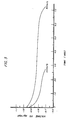
- a powder sample of a V53Ti33Ni14 was provided by subjecting the composition to an air hammer to achieve a -400 mesh (equivalent to approximately 38 micron diameter particle size). The powder was positioned over a pure nickel grid and pressed to 7 tons/sq.cm. Subsequently, the electrode was sintered at 825°C. for one hour. The electrochemical capacity of each powder composition was measured in a 4M KOH solution with a platinum counter electrode and an Hg/HgO reference electrode. The electrochemical capacity was measured at a discharge rate of 50 mA/g and the discharge rate capability of V53Ti33Ni14 at representative discharge rates versus time in Figure 4.
- the cycle life of the first group of compositions was measured by testing certain representative compositions as either a chunk sample or a powder sample. For instance, a chunk sample of V53Ti33Ni14 cycled for more than 10 cycles in 4M KOH at a charge rate of 100 mA/g for 6 hours and a discharge rate of 100 mA/g to -.700 volt vs. Hg/HgO reference electrode. No significant degradation was observed.
- Compositions having the specific formulae presented in Table 2 were prepared by weighing and mixing powders of the individual components each having a purity in excess of 99.5%. Each mixture was pressed into a pellet and melted by induction melting in an argon atmosphere. The ingot was cooled by an ice bath and then crushed with an air hammer. Chunk samples ranging up to 1.0 mm. thick and 300 mg. in weight were chosen for electrochemical testing.
- a chunk sample of each composition was squeeze wrapped by a pure nickel screen basket about 1 cm.2 and placed in a 4M KOH solution with a platinum counter electrode and an Hg/HgO reference electrode.
- the open circuit voltage was about -.970 volts vs. Hg/HgO.
- the electrochemical capacity of each composition was measured at 50 mA/g discharge rate is represented in Table 2.
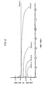
- Figure 5 demonstrates the discharge rate capability of a sample material from this group in chunk form at representative discharge rates versus time.
- the cycle life of this third Qroup of compositions was measured by testing a representative composition as a chunk sample.
- the composition Ti17V33Zr16Ni34 completed more than 120 cycles in 4M KOH at a charge rate of 200 mA/g for 3 hours and a discharge rate of 100 mA/g to -.720 volt vs. Hg/HgO reference electrode. No significant degradation was observed.
- Three compositions having the specific formulae presented in Table 3 were prepared by weighing and mixing powders of the individual components each having a purity in excess of 99.5%. Each mixture was pressed into a pellet and melted by induction melting in an argon atmosphere. The ingot was cooled by an ice bath and then crushed with an air hammer. Chunk samples ranging up to 1.0 mm thick and 300 mg. in weight were chosen for electrochemical testing.
- a chunk sample of each composition was squeeze wrapped by a pure nickel screen basket about 1cm.2 and placed in a 4M KOH solution with a platinum counter electrode and an Hg/HgO reference electrode.
- the open circuit voltage was about -.970 volt vs. Hg/HgO.
- the electrochemical capacity of each composition measured at a 50 mA/g discharge rate is represented in Table 3.
- Figure 6 demonstrates the discharge rate capability of a sample material from this group in chunk form at representative discharge rates versus time.
- a powder sample of a Ti17Cr17V53Ni13 was provided by subjecting the composition to an air hammer to achieve a -400 mesh. The powder was positioned over a pure nickel grid and pressed to 10 tons/sq.cm. Subsequently, the electrode was sintered at 1050°C. for 5 minutes. The electrochemical capacity of each powder composition was measured in a 4M KOH solution with a platinum counter electrode and an Hg/HgO reference electrode. The electrochemical capacity was measured at a discharge rate of 50 mA/g and the discharge rate capability at representative discharge rates versus time in Figure 7.
- compositions were measured by compositions as both a chunk sample and a powder sample. For instance, a chunk sample of Ti17Cr17V53Ni13 cycled for more than 150 cycles in 4M KOH at a charge rate of 100 mA/g for 6 hours and a discharge rate of 100 mA/g to -.720 volt vs. Hg/HgO reference electrode. No significant degradation was observed.
- An ingot of a Ti33Ni14V53 material was made by weighing out respective amounts of the elemental metals, melting them together, and allowing it to cool to room temperature. Two hundred grams of the material was placed into a reaction vessel with an interior volume of about 1 liter. The vessel was leak tight to both vacuum and pressurized gas. The vessel was evacuated to 10 ⁇ 3 torr and pressurized to about 600 psi. with commercial grade hydrogen gas. The material was allowed to stand for about 10 hours. Without breaking the seal, the hydrogen gas was removed. The vessel was heated to 400°C. for several hours until the hydrogen pressure coming out of the vessel was negligible. Argon was introduced and the reactor was allowed to cool to room temperature. After the seal was broken, the ingot was observed to have been reduced to flakes and powders of an ash-like consistency.
- the flakes were then pulverized using a ball-mill for three hours yielding the following distribution: greater than 38 micron size 25.4%; 30 to 38 micron size 12.5%; 5 to 30 micron size 60.4%; and 5 micron size or less 1.8%. Material which was greater than 38 micron size were subsequently reduced by longer ball-milling.
- the 38 micron size particles then mixed with a nickel binder and pressed onto a conductive substrate of pure nickel mesh.
- the material filled mesh was then used as a hydrogen storage anode in a half-cell. This material showed an excellent electrochemical performance, equivalent to the material that had been air-hammered.
- An active material composition of the formula V53Ti17Cr16Ni14 was prepared in accordance with the procedure listed in Example 3. The active material was then hydrided as in Example 4 and reduced to size of about -200 mesh. A nickel binder was added to the active material in an amount of about 7 atomic percent. After pressing, the active material was sintered at 1050°C. for five minutes in an hydrogen/argon atmosphere.
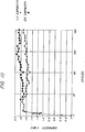
- a standard sub C size cell was fabricated with a Pellon separator using a 1.8 Ahr. positive electrode produced by Eagle-Picher. A 30% KOH electrolyte was added and the cell was cycled by charging at 300mA. for 8 hours. The initial capacity of the cell was approximately 1.7 Ahr. with a 1.0 volt cutoff. The capacity has maintained itself at approximately 1.7 Ahr. even after 170 cycles. Absolutely no degradation in the capacity has been observed.
- Figure 10 illustrates the cycling regimen for this electrode demonstrating its long cycle life with a sustained capacity.
- the present invention demonstrates a new and improved electrode, cell, and battery fabricated with novel active materials.
- the cells demonstrate bulk hydrogen storage with commercially acceptable charge and discharge rates, deep discharge capability, and long cycle life.
- the mechanical integrity of electrodes made with the inventive materials promotes long cycle life for the cells without substantial structural change or poisoning.
- the improved electrochemical performance and structural stability of the inventive electrodes is further benefited by economical fabrication. The ease and simplicity of their fabrication is demonstrated by the embrittlement process.
Abstract
Description
- The present invention-relates to rechargable electrochemical cells.
- Some research has been conducted involving hydrogen storage secondary batteries. However, a basic understanding resulting in a viable approach to optimizing such batteries has not been forthcoming in the scientific or patent literature. Examples of such efforts are U.S. Patents Nos. 3,669,745 and 3,824,131 and a technical paper entitled "A New Type of Reversible Negative Electrode for Alkaline Storage Batteries Based on Metal Alloy Hydrides," 1974, 8th International Power Sources Conference. These research efforts have not resulted in widespread commercial utilization of this battery technology. In fact, the prior research suggests no significant improvement over conventional battery systems such as nickel cadmium. As a result, the hydrogen storage battery system has apparently been ignored or abandoned.
- Secondary batteries using a hydrogen rechargeable electrode operate in a different manner than lead acid, nickel cadmium, or other battery systems. The hydrogen storage battery utilizes an anode which is capable of reversibly electrochemically storing hydrogen and usually employs a cathode of nickel hydroxide material. The anode and cathode are spaced apart in an alkaline electrolyte. Upon application of an electrical current to the anode, the anode material (M) is charged by the absorption of hydrogen:
M + H₂O + e⁻ ≷ M-H + OH⁻
Upon discharge the stored hydrogen is released to provide an electric current:
M-H + OH⁻ ≷ M + H₂O + e⁻
The reactions are reversible and this is also true of the reactions which take place at the cathode. As an example, the reactions at a conventional nickel hydroxide cathode as utilized in a hydrogen rechargeable secondary battery are as follows:
Charging: Ni(OH)₂ + OH⁻ ≷ NiOOH + H₂O + e⁻
Discharging: NiOOH + H₂O + e⁻ ≷ Ni(OH)₂ + OH⁻
- The battery utilizing an electrochemically hydrogen rechargeable anode offers important potential advantages over conventional secondary batteries. Hydrogen rechargeable anodes should offer significantly higher specific charge capacities than lead anodes or cadmium anodes. Furthermore, lead acid batteries and nickel-cadmium type secondary batteries are relatively inefficient, because of their low storage capacity and cycle life. A higher energy density should be possible with hydrogen storage batteries than these conventional systems, making them particularly suitable for battery powered vehicles and other mobile applications. Hydrogen storage batteries have not lived up to their potential, however, because of the materials and mechanical structures used.
- An example of hydrogen storage materials which are not readily useable for battery applications is found in Japanese Patent Application No. Sho53-164130 which was published July 11, 1980. A hydrogen storage metal material is disclosed with the composition formula (V1-xTix)₃ Ni1-yMy, whereas M is Cr, Mn, Fe; 0.05 <= x <= 0.8 and 0 <= y <= 0.6. The temperature and pressure conditions for using this material for effective hydrogen storage, however, exceed the normal conditions at which commercially acceptable batteries safely operate. Other problems, like corrosion also must be alleviated if these hydrogen storage materials are used in a battery.
- The preparation of hydrogen storage materials and fabrication of electrodes also are of utmost importance. It is desirable that the hydrogen storage materials be somewhat homogeneous to provide uniformity in their electrochemical properties. Often the individual components of the hydrogen storage materials are combined by melting the components together to form a bulk material such as an ingot. The hydrogen storage materials produced in this form are unsuitable for immediate use without further processing. Reducing the size of these bulk materials for fabrication as an electrode, however, can be quite difficult because of the unusual hardness and ductility of many hydrogen storage materials. Normal size reduction techniques which use such devices as jaw crushers, mechanical attritors, ball mills, and fluid energy mills often fail to economically reduce the size of such hydrogen storage materials. Thus, grinding and crushing operations for these materials have been complicated and the results have not been uniform.
- Attempts to make metals brittle in order to crush them more easily are not new in the art. Prior methods, however, have involved mechanical addition of embrittling agents, the presence of which would have an undesirable effect on the electrochemical properties of the hydrogen storage materials.
- Other methods for embrittling metals are disclosed in Canadian Patent No. 533,208 granted to Brown. This patent identifies many disadvantages of treating vanadium metal with hydrogen gas to facilitate its crushing and, instead, recommends using cathodic charging as a successful size reduction technique. Although one is dissuaded from using hydrogen gas by the Brown patent, the present invention overcomes the disadvantages to provide a useful and commercially desirable technique of size reduction.
- The previous attempts to utilise hydrogen storage materials in secondary batteries have proven unsuccessful because of the materials' poor electrochemical performance, structural instability, and expensive fabrication. The invention herein provides a new and improved battery and method of fabricating the same with an electrode incorporating an active material composition and structure allowing for high charge and discharge rates, efficient reversibility, high electrical efficiency, bulk hydrogen Storage without substantial structural change or poisoning, mechanical integrity over long cycle life, and deep discharge capability.
- In accordance with the present invention, a rechargeable electrochemical cell comprises a first electrode formed of an electrochemical hydrogen storage alloy having a compositional formula chosen from the group consisting of:
- (i) (TiV2-xNix)1-yMy where 0.2 ≦ x ≦ 1.0, 0.0 ≦ y ≦ 0.2, and M = Al or Zr;
- (ii) Ti2-x ZrxV4-yNiy where 0.0 ≦ x ≦ 1.5, and 0.6 ≦ y ≦ 3.5; and
- (iii)Ti1-xCrxV2-yNiy, where 0.00 ≦ x ≦ 0.75, and 0.20 ≦ y ≦ 1.0,
- The problems in prior art hydrogen storage materials discussed above are obviated by the present invention, all with improved electrochemical performance of the electrodes, cells, and batteries incorporating the novel active materials.
- The active materials of the present invention can also have the following novel compositions. A first group of active material compositions incorporate the elements of titanium present in an amount between about 28 and 36 atomic precent, vanadium present in an amount between about 40 and 56 atomic percent and nickel present in an amount between about 10 and 22 atomic percent. A second composition group incorporates the elements of titanium present in an amount between about 15 and 20 atomic percent, vanadium present in an amount between about 15 and 40 atomic percent, zirconium present in an amount between about 10 and 20 atomic percent, and nickel present in an amount between about 30 and 55 atomic percent. A preferred third composition group incorporates titanium present in an amount between about 15 and 25 atomic percent, vanadium present in an amount between about 45 and 55 atomic percent, chromium present in an amount between about 5 and 25 atomic percent, and nickel present in an amount between about 10 and 25 atomic percent.
- The active materials provided by the present invention also have novel structures. These materials may be single or multiphase combinations of amorphous, microcrystalline, or polycrystalline structures. Preferably, these materials have a multiphase polycrystalline structure. An active material for hydrogen storage electrode is provided by the present invention including a grain phase having means for reversibly storing hydrogen and a primary intergranular phase having means for catalyzing hydrogen oxidation. The primary intergranular phase is in operative contact with the grain phase.
- The present invention also provides a battery including a plurality of electrochemical cells. The active material incorporated in each of these devices is described above.
- A method of making an electrode using a hydrogen storage active material includes providing an active material of the composition and/or structure described above in a predetermined particle size distribution, and subsequently, fabricating an electrode with the sized material.
- A method of making hydrogen storage active material for use in an electrode includes the steps of providing an active material in bulk form having means for reversibly storing hydrogen and a homogeneous phase structure. Additional steps include hydriding the bulk material, dehydriding the bulk material, and pulverising the bulk material to a predetermined particle size distribution.
- A method of sizing a hydride-forming metallic alloy includes the steps of providing a hydride-forming metallic alloy in bulk form and hydriding the bulk alloy. Then the method includes dehydriding the bulk alloy and pulverising the alloy to a predetermined particle size distribution.
- The active material for the hydrogen storage electrode can include: titanium being present in an amount greater than about 28 and less than about 36 atomic percent; vanadium being present in an amount greater than about 40 and less than about 56 atomic percent; and nickel being present in an amount greater than about 10 and less than about 22 atomic percent. Another active material includes:
titanium being present in an amount greater than about 15 and less than about 20 atomic percent; vanadium being present in an amount grater than about 15 and less than about 40 atomic percent; zirconium being present in an amount greater than about 10 and less than about 20 atomic percent; and nickel being present in an amount greater than about 30 and less than about 55 atomic percent. Still another active material includes: titanium being present in an amount greater than about 5 and less than about 25 atomic percent; vanadium being present in an amount grater than about 40 and less than about 55 atomic percent; chromium being present in an amount greater than about 5 and less than about 25 atomic percent; and nickel being present in an amount greater than about 10 and less than about 25 atomic percent. - The active material for the hydrogen storage electrode may include the elements titanium, vanadium, and nickel. The active material exhibits a characteristic x-ray diffraction spectrum at the following d-spacings expressed in angstroms: 2.26-2.10, 1.55-1.48, and 1.27-1.21. Another active material includes the elements titanium, vanadium, zirconium, and nickel. This active material exhibits a characteristic x-ray diffraction spectrum at the following d-spacings expressed in angstroms: 2.10-2.07 and 1.40-1.24.
- The active materials for the hydrogen storage electrode may include a grain phase having means for reversibly storing hydrogen. The active materials also include a primary intergranular phase having means for catalyzing the hydrogen oxidation and lowering the heat of reaction with hydrogen.
- When the active material includes means for reversibly storing hydrogen and has a homogenous phase structure, the electrode may be made by hydriding, and subsequently, dehydriding, the bulk material. The method also includes pulverising the bulk material to a predetermined particle size distribution.
- Preferred embodiments of this invention will now be described by way of example with reference to the drawings accompanying this specification in which:
- Figure 1 is a cutaway side view of a flat cell embodiment;
- Figure 2 is a side view of a jelly-roll cell embodiment;
- Figure 3 is a graph of representative discharge currents versus time for an inventive active material of the first composition group in chunk form;
- Figure 4 is a graph of a representative discharge current versus time for an inventive active material of the first composition group in electrode form;
- Figure 5 is a graph of representative discharge currents versus time for an inventive active material of the second composition group in chunk form;
- Figure 6 is a graph of representative discharge currents versus time for an inventive active material of the third composition group in electrode form;
- Figure 7 is a graph of a representative discharge current versus time for an inventive active material of the third composition group in electrode form;
- Figure 8 is a scanning electron micrograph of an inventive active material of the first composition group before subjecting the material to an inventive process of preparation;
- Figure 9 is a scanning electron micrograph of the inventive material in Figure 8 after subjecting the material to the inventive process of preparation; and
- Figure 10 is a graph of the cell capacity versus cycle life of an inventive electrode incorporating an inventive active material of the third composition group.
- Generally, the present invention provides novel active materials which reversibly store hydrogen under conditions which make them exceptionally well-suited for electrochemical applications. These active materials have both novel compositions and structures. A first group of active material compositions incorporate the elements of titanium, vanadium, and nickel. A second composition group adds zirconium to the first group of active materials. A preferred third composition group adds chromium to the first group of active materials. These materials may be single or multiphase combinations of amorphous, microcrystalline, or polycrystalline structures. Preferably, these materials have a multiphase polycrystalline structure.
- The inventive active materials may be prepared by several methods disclosed herein. A method of reducing the size or sizing these materials, as well as other hydride-forming alloys, also is provided. Methods of fabricating inventive hydrogen storage electrodes from these active materials are contemplated. The inventive electrodes are adaptable to assembly as cells with various configurations such as a jelly-roll or flat configuration. Electrochemical cells and batteries assembled with the inventive electrodes provide significantly improved capacity and cycle life.
- In particular, the present invention provides active materials having three primary groups of compositions which absorb and store hydrogen and subsequently release at least a portion of the stored hydrogen to provide a supply of electrons. Suitable active materials of the first composition group include titanium present in an amount greater than about 28 and less than about 36 atomic percent, vanadium present in an amount greater than about 40 and less than about 56 atomic percent, and nickel present in an amount greater than about 10 and less than about 22 atomic percent. A preferred active material in this group includes about 33 atomic percent of titanium, 53 atomic percent of vanadium, and 14 atomic percent of nickel.
- In addition to the above components, the first group of compositions may also include aluminum and/or zirconium present in an amount less than about 10 atomic percent. If one or both of these elements are incorporated, a preferred amount is about 7 atomic percent of zirconium and/or about 5 atomic percent of aluminum.
- More specifically, the first composition group includes active materials which are represented by the composition formula (TiV2-xNix)1-yMy whereas, 0.2 <= x <= 1.0; 0 <= y <= 0.2; and M=A1 or Zr. Preferably, y=0 and 0.40 <= x <= 0.45.
- The structures of the compositions disclosed herein were characterized by x-ray diffraction, scanning electron microscopy, and energy dispersive x-ray analysis. The types of structure provided by the invention included both single and multiple phases. An individual phase may have a structure which is amorphous, microcrystalline, or polycrystalline (with or without long range order). An active material with multiple phases may have any combination of these structures. Preferably, the active materials of all three composition groups have a multiphase polycrystalline structure.
- In particular, the preferred multiphase polycrystalline structure of the active materials in the first composition group includes a grain phase which is a solid solution of titanium and vanadium with dissolved nickel. The titanium and vanadium act as hydrogen storage components while the nickel functions as catalyst and also lowers the heat of reaction with hydrogen. The composition of this phase varies from about 20:80 to 30:70 as a ratio of titanium: vanadium measured in atomic percent. The dissolved nickel is present in an amount between about 4 to 8 atomic percent.
- Between the grain phases of the preferred polycrystalline structure is a primary intergranular phase including a titanium and nickel intermetallic compound with dissolved vanadium. Such an intermetallic compound exhibits distinct phases where the constituent atoms are in fixed integral ratios and is held together by metallic bonding to usually form a crystal structure. The primary intergranular phase contains approximately equal amounts of titanium and nickel, and the dissolved vanadium is present in an amount between about 6 to 8 atomic percent. This phase functions as a catalyst for hydrogen oxidation of the primary hydrogen storage grain phase. The titanium and nickel intermetallic compound stores less hydrogen than the grain phase and acts as a channel for hydrogen oxidation. The vanadium dissolved in the primary intergranular phase increases the hydrogen storage capacity of this phase and the heat of reaction with hydrogen.
- Several other phases also may be present in these materials. For example, the grain phase may be at least partially surrounded by a grain boundary phase which is a non-equilibrium solid solution of titanium and vanadium with dissolved nickel. Such a non-equilibrium phase is not in its lowest energy configuration and may exhibit concentration gradients within the phase. A composition of the grain boundary phase is between about 45:55 to 55:45 as a ratio of titanium:vanadium measured in atomic percent. The dissolved nickel is present in an amount between about 10 to 14 atomic percent.
- Another example is a non-equilibrium phase which includes Ti₂Ni with dissolved vanadium present in an amount between about 7 to 13 atomic percent. Still another phase may be the vanadium rich side of the titanium and vanadium binary.
- As previously mentioned, the preferred structures of the three composition groups were characterized by x-ray diffraction. The major identified peaks of the preferred polycrystalline structure of the first composition group occurred at d-spacings of 2.26 angstroms to 2.10 angstroms, 1.55 angstroms to 1.48 angstroms, and 1.27 angstroms to 1.21 angstroms. The primary hydrogen storage grain phase of the preferred structures is a single phase alloy which exhibits d-spacings closely corresponding to a vanadium structure with its lattice parameters shifted due to the incorporation of varying amounts of other components like titanium and nickel. Other small peaks of the x-ray spectrum may be associated with the intergranular and/or grain boundary phases found in the material. The occurrence of the peaks in the x-ray diffraction spectrum depends on its composition and preparation history.
- A second composition group contemplated by the present invention as an active material for an hydrogen storage electrode includes titanium present in an amount greater than about 15 and less than about 20 atomic percent, vanadium present in an amount greater than about 15 and less than about 40 atomic percent, zirconium present in an amount greater than about 10 and less than about 20 atomic percent, and nickel present in an amount greater than about 30 and less than about 55 atomic percent. Preferably, a composition includes approximately 17 atomic percent titanium, 33 atomic percent vanadium, 16 atomic percent zirconium, and 34 atomic percent nickel. A second preferred composition includes approximately 17 atomic percent titanium, 20 atomic percent vanadium, 16 atomic percent zirconium, and 47 atomic percent nickel.
- More specifically, the second composition group includes active materials which are represented by the composition formula Ti2-xZrxV4-yNiy whereas 0 < x <= 1.5 and 0.6 <= y <= 3.5. Preferably, 0.95 <= x <= 1.05 and y = 2 or 3.
- The preferred multiphase Polycrystalline structure of the active materials in the second composition group also includes a grain phase which is an intermetallic compound of vanadium, titanium, zirconium, and nickel. Again, the grain phase reversibly stores hydrogen. A composition of this grain phase is about 26:16:22:36 as a ratio of vanadium: titanium:zirconium:nickel measured in atomic percent.
- Between the grain phases of the preferred polycrystalline structure is a primary intergranular phase including a titanium, zirconium, and nickel intermetallic compound with dissolved vanadium. A composition of this primary intergranular phase is about 25:20:46 as a ratio of titanium:zirconium:nickel measured in atomic percent. The dissolved vanadium is present in an amount of about 9 atomic percent.
- Several other phases also may be present in these materials For example, the grain phase may be at least partially surrounded by a grain boundary phase which is a non-equilibrium phase incorporating titanium, vanadium, zirconium, and nickel. A composition of the grain boundary phase is about 19:20:22:39 as a ratio of titanium:vanadium: zirconium:nickel as measured in atomic percent.
- The x-ray diffraction analysis of the preferred crystalline structure of the second composition group identified peaks at d-spacings of 2.30 angstroms to 2.07 angstroms and 1.40 angstroms to 1.24 angstroms. Other small peaks of the x-ray spectrum may be associated with the inter-granular and/or grain boundary phases found in the material. The occurrence of the peaks in the x-ray diffraction spectrum depends on its composition and preparation history.
- A third composition group contemplated by the present invention as an active material for an hydrogen storage electrode includes titanium present in an amount greater than about 5 and less than about 25 atomic percent, vanadium present in an amount greater than about 40 and less than about 55 atomic percent, chromium present in an amount greater than about 5 and less than about 25 atomic percent, and nickel present in an amount greater than about 10 and less than about 25 atomic percent. Preferably, a composition would have approximately 17 atomic percent titanium, 53 atomic percent vanadium, 17 atomic percent chromium, and 13 atomic percent nickel.
- More specifically, the third composition group includes active materials which are represented by the composition formula Ti1-xCrxV2-yNiy whereas, 0 < x <= 0.75; 0.2 <= y <= 1.0. Preferably, 0.45 <= x <= 0.55 and 0.4 <= y <= 0.6.
- The preferred structure of the active materials in the third composition group is a multiphase polycrystalline structure. The active materials include a grain phase which is a solid solution of titanium, vanadium, and chromium with dissolved nickel. The titanium, vanadium, and chromium act as the hydrogen storage components while the nickel functions as a catalyst and lowers the heat of reaction with hydrogen. A composition of the grain phase is between about 60 to 70 atomic percent of vanadium, 20 to 30 atomic percent of chromium, 3 to 10 atomic percent of titanium, and 3 to 10 atomic percent of nickel.
- Between the grains is an intergranular phase including a titanium, vanadium, and nickel intermetallic compound with dissolved chromium. The intergranular phase functions as a hydrogen oxidation catalyst for the utilization of the primary hydrogen storage grain phase. The intergranular phase also stores hydrogen, but to significantly lesser degree than the grain phase. A composition of this phase is between about 20 to 50 atomic percent of titanium, 40 to 50 atomic percent of nickel, 5 to 20 atomic percent of vanadium, and 1 to 5 atomic percent of chromium. The actual composition and the volume fraction of each phase depends on the thermal history of its preparation and processing as previously discussed.
- The grain phase may be surrounded by a grain boundary phase which is a solid solution of titanium and vanadium with dissolved chromium and nickel. A composition and volume amount of this phase depends on its thermal history of preparation and processing.
- The preferred structures of all three composition groups may be characterized by a suitable size for the polycrystalline phases. The grain phase may vary between about 10 to 100 microns in diameter. The intergranular phase width may vary between about 1 to 20 microns. The preferred size of the grain phase is about 25 microns with an intergranular phase of about 3 microns in width.
- The preferred structures for all three composition groups may be characterized by the volume amounts of the individual polycrystalline phases. A suitable volume amount of a grain phase is about 75% to 95% with a primary intergranular phase present in substantially the remaining volume amount. A grain boundary phase or other intergranular phases, if any, would be present in an amount of about 2%.
- The volume amounts of the non-equilibrium phases present in the active material depend on the preparation of the material. The means of processing as well as the thermal history of preparing the active material and fabricating the electrode determine the volume amounts of any non-equilibrium phase.
- The present invention also provides the hydrides of the active materials in each of the composition groups. The hydrides of the first composition group preferably incorporate about 3.8 weight percent of hydrogen. The hydrides of the second composition group preferably incorporate about 1.2 weight percent of hydrogen. The hydrides of the third composition group preferably incorporate about 1.4 weight percent of hydrogen.
- The x-ray diffraction analysis of the preferred polycrystalline structure of the third composition group identified peaks at d-spacings similar to that found for the preferred polycrystalline structures of the first composition group. Likewise, the primary hydrogen storage grain phase of the preferred structures is a single phase alloy which exhibits d-spacings closely corresponding to a vanadium structure with its lattice parameters shifted due to the incorporation of varying amounts of other components like titanium, chromium, and nickel.
- The present invention contemplates a number of methods for preparing the above described active materials. Suitable methods reproducibly prepare the materials with both composition and structure that is somewhat homogeneous. It was found that appropriate amounts of the individual components of the material could be starting reactants in a melting process to form a bulk composition or ingot. Although not limited to a melting process to form the material, the invention contemplates conventional techniques such as arc-melting and preferably induction melting for their preparation.
- Once the materials were formed in bulk, it became necessary to reduce the material to a more appropriate size. Conventional sizing techniques like those previously mentioned did not prove suitably effective from a commercial standpoint. Air hammering eventually was selected, but still was considered commercially undesirable.
- It was then discovered that through a novel hydriding process, the materials could be embrittled, making pulverization much easier and more economical. The hydriding process includes the steps of hydriding the active material in bulk form and dehydriding the active material either before or after pulverizing the material to the appropriate size. The hydriding step changes the physical form of the material from a hard, tough ingot into a flaky, ash-like consistency. This ash-like material is readily pulverized.
- The hydriding step includes contacting the bulk material with hydrogen gas under the appropriate temperature, pressure, and time conditions to form the hydride of the material. More specifically, an ingot of the material may be placed in a reaction vessel. The vessel is subsequently sealed and evacuated. Generally, a pressure of about 10 torr is suitable. The vessel is then pressurized with hydrogen gas between about 100 to 2000 psi. Generally, maintaining a partial pressure of hydrogen above about 200 psi for a few minutes is sufficient to form the hydride at room temperature. These conditions depend on the composition of the material and its geometry. Materials that have a slower diffusion rate or low interstitial mobility for hydrogen will require more time for suitable embrittlement. The factors that affect the mobility of hydrogen through the phase regions and of the material's structure will determine the pressure, time, and temperature necessary to form a hydride of the material and effectuate suitable embrittlement.
- The vessel may be cooled during the hydriding step to prevent any temperature increase. The temperature inside the vessel rises as the material is exposed to the hydrogen due to the exothermic nature of the hydride formation reaction (approximately 10 Kcal./mole for these materials). Without any cooling, the temperature inside the vessel usually elevates to about 250°C. A temperature increase delays the formation of the hydride. The hydriding reaction spontaneously starts upon exposure to hydrogen gas. If a barrier or passivation layer forms on the surface of the material which prevents contact with the hydrogen gas, the layer should be removed. For example, if an oxide layer forms on the material, the hydrogen initially will slowly penetrate. Initial heating of the material accelerates the hydriding step. Once a portion of the material's surface is cleaned of the layer, the hydriding reaction proceeds rapidly without further assistance.
- Hydride formation of a material batch is governed by the ideal gas law. Sufficient embrittlement for easy size reduction of sore materials does not require complete hydride formation. For example, with a material such as Ti₅₃Ni₃₃V₁₄ which absorbs 2.5 weight percent hydrogen, it was found that hydriding to at least about 1.5 weight percent hydrogen provides sufficient embrittlement. Using the ideal gas law and the amount of hydrogen absorbed for sufficient embrittlement, the reaction vessel necessary to embrittle a given batch of material can be readily calculated.
- Another step of the novel process is the dehydriding of the material. Dehydriding the material takes place after the material has been sufficiently embrittled by hydride formation. The hydride is returned to the metallic form of the material.
- Specifically, dehydriding includes evacuating the vessel with the hydride still inside the reaction vessel and with heating for a sufficient time period to induce release of the incorporated hydrogen. The material should be kept at a temperature sufficiently low to avoid changing the structure of the material. A temperature below 600°C. is usually suitable. The dehydriding step is more quickly completed as the temperature increases. Thus, a temperature of about 400°C. is preferred. As the hydrogen is removed from the vessel it may be compressed and recycled since it is largely uncontaminated.
- After the hydrogen is removed, the material is cooled to room temperature in an inert environment like argon. The resultant material has the ash-like features of the hydride and is relatively inert to atmospheric reaction.
- Pulverization of the embrittled material may be accomplished by any conventional device such as mechanical attritors, jaw crushers, air-hammer, hardened steel mortar and pestle, or ball-milling. Ball-milling the material gives a particle size distribution especially useful for the fabrication of hydrogen storage electrodes. The particle size of the material may be varied depending upon the application. The flakes resulting from the embrittlement process are usually about 100 mm. in diameter. Care must be taken during the pulverization process not to expose the pulverized material to any conditions which may allow water or oxygen to contact or react with the pulverized alloy. Using other pulverization techniques will produce different distributions of particle sizes, as well as different particle shapes.
- It is important, although not critical, that the pulverizing step follow the dehydriding step. Several significant advantages are demonstrated if the preferred sequence of steps is followed. First, the hydrided form of the material is very reactive with certain gases like oxygen which would deleteriously offset the electrochemical properties of the material. Pulverizing the material after dehydriding reduces the likelihood of contamination. This is not critical because the material could be pulverized in the hydride form without contamination if care were taken to provide an inert environment. The complexity of the procedure, however, makes it less likely to be economically feasible. Second, a single vessel may be used to hydride and dehydride the material without transporting the material between steps. Thus, contamination and costly handling are avoided.
- The novel hydriding process provided herein, may be in the preparation of materials other than the disclosed active material. Other materials suitable for size reduction with the inventive process are hydride formers.
- The present invention contemplates the fabrication of an hydrogen storage electrode from an active material of the composition or structure previously discussed. The active material may be sized to an appropriate particle distribution for preparing the electrodes. Although the material may be of any convenient particle size, we have found that the preferred compositions described above demonstrate the highest electrochemical capacity where the material has been sized to approximately 38µ or about -400 mesh.
- The fabrication of the electrodes using the above described active material may be carried out by several conventional processes. Preferably, the active materials were mixed with a binder such as nickel in the amount of about 7%. Other binders which promote the mechanical stability of the electrode without deleteriously affecting its electrochemical properties are suitable. This active material and binder was then placed in contact with a current collector. Although nickel mesh screen was used, other current collecting means also are suitable.
- The material was then pressed to a pressure of about 7 to 10 tons/sq.cm. Various conventional methods for, effectuating the pressure are contemplated by the present invention.
- These materials are then sintered in the range of 800° to 1200°C. for a period of several minutes to an hour. Preferably, a temperature of about 1050°C. is used for about five minutes. As the temperature of the sintering process decreased the length for sintering increased. It is economically preferred to have a higher sintering temperature for a shorter period of time.
- The present invention also contemplates an electrochemical cell which includes at least one electrode means for storing energy. The electrode means is formed from an active material of the composition or structure previously discussed. The cell also includes at least one counter electrode means providing far the release of the energy stored in said electrode means. The counter electrode means is spaced in operative contact with the electrode means. The cell also includes a casing which has the electrode means and the counter electrode means positioned therein. The counter electrode means includes an electrolyte placed in operative contact with the electrode means and the counter electrode means. A plurality of these cells may be assembled to produce a hydrogen storage battery.
- Various electrochemical cell embodiments utilizing the inventive active material compositions are contemplated. Referring to Figure 1, a
flat cell 10 is illustrated which uses at least one substantiallyflat plate 15 incorporating the active material described above. Interleaved between the active material is acurrent collector 20 which is in electrical contact with the active material and atab 25. Thecollector 20 andtab 25 may be made of suitably conductive metals such as nickel. Theflat cell 10 includes acounter electrode 30 which is substantially flat and aligned to be in operative contact withplate 15. Aseparator 35 is disposed between thecounter electrode 30 and theplate 15. - A second substantially
flat plate 40 may be spaced in operative contact with thecounter electrode 30 on the side opposite thefirst plate 15. Similarly interleaved between the active material is a current collector 45 which is in electrical contact with the active material and thetab 50. Asecond separator 55 is disposed between thesecond plate 40 and the counter electrode to electrically contact thetab 50 and thecounter electrode 30. - The
cell 10 depicted in Figure 1 may be sealed in a suitable material, such as aplastic wrap 60, which does not deteriorate in contact with the electrolyte used and allows venting of thecell 10 should it gas during operation. The first andsecond tabs leads 65 which extends outside of thecell plastic 60. Likewise, asecond lead 70 electrically connects to thecounter electrode 30 and extends outside of thecell plastic 60. - Figure 2 illustrates a commercially preferred jelly-
roll cell 100 which is made by spirally winding a flat cell about anaxis 105. The jelly-roll cell may then be placed in a can which contains a conductive electrolyte (not shown) which contacts thetabs 110 interleaved with theplate 115 of the material described above. Aseparator 120 is spaced between thesheets 115 and acounter electrode 125. - A first group of compositions represented by the formula (TiV2-xNix)1-yMy whereas, 0.2 <= x <= 1.0; 0 <= y <= 0.2; and M=Al or Zr. Compositions having these specific formulae presented in Table 1 were prepared by weighing and mixing powders of the individual components each having a purity in excess of 99.7%. Each mixture was pressed into a pellet and melted by induction melting in an argon atmosphere. The ingot was cooled by an ice bath and then crushed with an air hammer. Chunk samples ranging up to 1.0 mm. in length and 250 mg. in weight were chosen for electrochemical testing.
- Each chunk sample of a composition was squeeze wrapped by a pure nickel screen basket about 1 cm.² and placed in a 4M KOH solution with a platinum counter electrode and an Hg/HgO reference electrode. The open circuit voltage was about -.970 volt vs. Hg/HgO the electrochemical capacity of each composition measured at a 50 mA/g discharge rate is represented in Table 1.

- Figure 3 demonstrates the discharge rate capability of V₅₃Ti₃₃Ni₁₄ material from this group in chunk form at representative discharge rates versus time.
- A powder sample of a V₅₃Ti₃₃Ni₁₄ was provided by subjecting the composition to an air hammer to achieve a -400 mesh (equivalent to approximately 38 micron diameter particle size). The powder was positioned over a pure nickel grid and pressed to 7 tons/sq.cm. Subsequently, the electrode was sintered at 825°C. for one hour. The electrochemical capacity of each powder composition was measured in a 4M KOH solution with a platinum counter electrode and an Hg/HgO reference electrode. The electrochemical capacity was measured at a discharge rate of 50 mA/g and the discharge rate capability of V₅₃Ti₃₃Ni₁₄ at representative discharge rates versus time in Figure 4.
- The cycle life of the first group of compositions was measured by testing certain representative compositions as either a chunk sample or a powder sample. For instance, a chunk sample of V₅₃Ti₃₃Ni₁₄ cycled for more than 10 cycles in 4M KOH at a charge rate of 100 mA/g for 6 hours and a discharge rate of 100 mA/g to -.700 volt vs. Hg/HgO reference electrode. No significant degradation was observed.
- A second group of compositions represented by the formula Ti2-xZrxV4-yNiy whereas 0 < x <= 1.5; 0.6 <= y <= 3.5. Compositions having the specific formulae presented in Table 2 were prepared by weighing and mixing powders of the individual components each having a purity in excess of 99.5%. Each mixture was pressed into a pellet and melted by induction melting in an argon atmosphere. The ingot was cooled by an ice bath and then crushed with an air hammer. Chunk samples ranging up to 1.0 mm. thick and 300 mg. in weight were chosen for electrochemical testing.
- A chunk sample of each composition was squeeze wrapped by a pure nickel screen basket about 1 cm.² and placed in a 4M KOH solution with a platinum counter electrode and an Hg/HgO reference electrode. The open circuit voltage was about -.970 volts vs. Hg/HgO. The electrochemical capacity of each composition was measured at 50 mA/g discharge rate is represented in Table 2.

- Figure 5 demonstrates the discharge rate capability of a sample material from this group in chunk form at representative discharge rates versus time.
- The cycle life of this third Qroup of compositions was measured by testing a representative composition as a chunk sample. Particularly, the composition Ti₁₇V₃₃Zr₁₆Ni₃₄ completed more than 120 cycles in 4M KOH at a charge rate of 200 mA/g for 3 hours and a discharge rate of 100 mA/g to -.720 volt vs. Hg/HgO reference electrode. No significant degradation was observed.
- A third group of compositions represented by the formula Ti1-xCrxV2-yNiy whereas 0 < x <= 0.75 and 0.2 <= y <= 1.0. Three compositions having the specific formulae presented in Table 3 were prepared by weighing and mixing powders of the individual components each having a purity in excess of 99.5%. Each mixture was pressed into a pellet and melted by induction melting in an argon atmosphere. The ingot was cooled by an ice bath and then crushed with an air hammer. Chunk samples ranging up to 1.0 mm thick and 300 mg. in weight were chosen for electrochemical testing.
- A chunk sample of each composition was squeeze wrapped by a pure nickel screen basket about 1cm.² and placed in a 4M KOH solution with a platinum counter electrode and an Hg/HgO reference electrode. The open circuit voltage was about -.970 volt vs. Hg/HgO. The electrochemical capacity of each composition measured at a 50 mA/g discharge rate is represented in Table 3.

- Figure 6 demonstrates the discharge rate capability of a sample material from this group in chunk form at representative discharge rates versus time.
- A powder sample of a Ti₁₇Cr₁₇V₅₃Ni₁₃ was provided by subjecting the composition to an air hammer to achieve a -400 mesh. The powder was positioned over a pure nickel grid and pressed to 10 tons/sq.cm. Subsequently, the electrode was sintered at 1050°C. for 5 minutes. The electrochemical capacity of each powder composition was measured in a 4M KOH solution with a platinum counter electrode and an Hg/HgO reference electrode. The electrochemical capacity was measured at a discharge rate of 50 mA/g and the discharge rate capability at representative discharge rates versus time in Figure 7.
- The cycle life of this second group of compositions was measured by compositions as both a chunk sample and a powder sample. For instance, a chunk sample of Ti₁₇Cr₁₇V₅₃Ni₁₃ cycled for more than 150 cycles in 4M KOH at a charge rate of 100 mA/g for 6 hours and a discharge rate of 100 mA/g to -.720 volt vs. Hg/HgO reference electrode. No significant degradation was observed.
- An ingot of a Ti₃₃Ni₁₄V₅₃ material was made by weighing out respective amounts of the elemental metals, melting them together, and allowing it to cool to room temperature. Two hundred grams of the material was placed into a reaction vessel with an interior volume of about 1 liter. The vessel was leak tight to both vacuum and pressurized gas. The vessel was evacuated to 10⁻³ torr and pressurized to about 600 psi. with commercial grade hydrogen gas. The material was allowed to stand for about 10 hours. Without breaking the seal, the hydrogen gas was removed. The vessel was heated to 400°C. for several hours until the hydrogen pressure coming out of the vessel was negligible. Argon was introduced and the reactor was allowed to cool to room temperature. After the seal was broken, the ingot was observed to have been reduced to flakes and powders of an ash-like consistency.
- Scanning electron micrographs were taken before hydriding in Figure 8 and after hydriding in Figure 9. These micrographs dramatically show cracking of the material around the various phase regions. Yet, the structure of the material remains unchanged.
- The flakes were then pulverized using a ball-mill for three hours yielding the following distribution: greater than 38 micron size 25.4%; 30 to 38 micron size 12.5%; 5 to 30 micron size 60.4%; and 5 micron size or less 1.8%. Material which was greater than 38 micron size were subsequently reduced by longer ball-milling.
- The 38 micron size particles then mixed with a nickel binder and pressed onto a conductive substrate of pure nickel mesh. The material filled mesh was then used as a hydrogen storage anode in a half-cell. This material showed an excellent electrochemical performance, equivalent to the material that had been air-hammered.
- An active material composition of the formula V₅₃Ti₁₇Cr₁₆Ni₁₄ was prepared in accordance with the procedure listed in Example 3. The active material was then hydrided as in Example 4 and reduced to size of about -200 mesh. A nickel binder was added to the active material in an amount of about 7 atomic percent. After pressing, the active material was sintered at 1050°C. for five minutes in an hydrogen/argon atmosphere.
- A standard sub C size cell was fabricated with a Pellon separator using a 1.8 Ahr. positive electrode produced by Eagle-Picher. A 30% KOH electrolyte was added and the cell was cycled by charging at 300mA. for 8 hours. The initial capacity of the cell was approximately 1.7 Ahr. with a 1.0 volt cutoff. The capacity has maintained itself at approximately 1.7 Ahr. even after 170 cycles. Absolutely no degradation in the capacity has been observed. Figure 10 illustrates the cycling regimen for this electrode demonstrating its long cycle life with a sustained capacity.
- The present invention demonstrates a new and improved electrode, cell, and battery fabricated with novel active materials. The cells demonstrate bulk hydrogen storage with commercially acceptable charge and discharge rates, deep discharge capability, and long cycle life. The mechanical integrity of electrodes made with the inventive materials promotes long cycle life for the cells without substantial structural change or poisoning. The improved electrochemical performance and structural stability of the inventive electrodes is further benefited by economical fabrication. The ease and simplicity of their fabrication is demonstrated by the embrittlement process.
wherein the hydrogen storage alloy comprises at least one phase chosen from the group consisting of amorphous, microcrystalline, polycrystalline, and combinations thereof, and wherein the first electrode is charged by absorption of hydrogen according to the reaction:
M + H₂O + e- = M-Hydride + OH-, and discharged by
desorption of hydrogen according to the reaction:
M-Hydride + OH- = M, + H₂O + e-;
a second electrode which is oxidised on charge and reduced on discharge; and,
an aqueous alkaline electrolyte between and in contact with the first and second electrodes.
Claims (6)
- A rechargeable electrochemical cell comprising a first electrode (15) formed of an electrochemical hydrogen storage alloy having a compositional formula chosen from the group consisting of:(i) (TiV2-xNix)1-yMy where 0.2 ≦ x ≦ 1.0, 0.0 ≦ y ≦ 0.2, and M = A1 or Zr;(ii) Ti2-x ZrxV4-yNiy where 0.0 ≦ x ≦ 1.5, and 0.6 ≦ y ≦ 3.5; and(iii)Ti1-xCrxV2-yNiy, where 0.00 ≦ x ≦ 0.75, and 0.20 ≦ y ≦ 1.0,wherein the hydrogen storage alloy comprises at least one phase chosen from the group consisting of amorphous, microcrystalline, polycrystalline, and combinations thereof, and wherein the first electrode is charged by absorption of hydrogen according to the reaction:
M + H₂O + e- = M-Hydride + OH-, and discharged by
desorption of hydrogen according to the reaction:
M-Hydride + OH- = M, + H₂O + e-;
a second electrode (40) which is oxidised on charge and reduced on discharge; and,
an aqueous alkaline electrolyte between and in contact with the first and second electrodes. - A cell according to claim 1, wherein the second electrode comprises nickel hydroxide.
- A cell according to claim 1 or claim 2, wherein the hydrogen storage alloy includes:
a grain phase having a solid solution of said titanium and said vanadium with said nickel dissolved therein; and
a primary intergranular phase having an intermetallic compound of said titanium and said nickel with said vanadium dissolved therein, said intergranular phase in operative contact with said grain phase. - A cell according to claim 3, wherein said hydrogen storage alloy further includes a grain boundary phase having a solid solution of said titanium and said vanadium with said nickel dissolved therein, said grain boundary phase in operative contact with said grain phase.
- A cell according to claim 3, wherein said hydrogen storage alloy further includes a secondary intergranular phase having an intermetallic compound of Ti₂Ni with vanadium dissolved in said intermetallic compound in an amount between about 7 to 13 atomic percent.
- A cell according to claim 3, wherein said hydrogen storage alloy further includes a secondary intergranular phase comprising a vanadium rich side of the titanium and vanadium binary.
Priority Applications (1)
| Application Number | Priority Date | Filing Date | Title |
|---|---|---|---|
| AT85302491T ATE67049T1 (en) | 1984-04-18 | 1985-04-09 | HYDROGEN STORAGE MATERIALS AND METHODS OF CALIBRATION AND MANUFACTURING SAME FOR ELECTROCHEMICAL APPLICATIONS. |
Applications Claiming Priority (2)
| Application Number | Priority Date | Filing Date | Title |
|---|---|---|---|
| US601641 | 1984-04-16 | ||
| US06/601,641 US4551400A (en) | 1984-04-18 | 1984-04-18 | Hydrogen storage materials and methods of sizing and preparing the same for electrochemical applications |
Publications (3)
| Publication Number | Publication Date |
|---|---|
| EP0161075A2 EP0161075A2 (en) | 1985-11-13 |
| EP0161075A3 EP0161075A3 (en) | 1986-10-01 |
| EP0161075B1 true EP0161075B1 (en) | 1991-09-04 |
Family
ID=24408227
Family Applications (1)
| Application Number | Title | Priority Date | Filing Date |
|---|---|---|---|
| EP85302491A Expired - Lifetime EP0161075B1 (en) | 1984-04-17 | 1985-04-09 | Hydrogen storage materials and methods of sizing and preparing the same for electrochemical applications |
Country Status (12)
| Country | Link |
|---|---|
| US (1) | US4551400A (en) |
| EP (1) | EP0161075B1 (en) |
| JP (2) | JP2951331B2 (en) |
| KR (1) | KR920007384B1 (en) |
| AT (1) | ATE67049T1 (en) |
| AU (1) | AU583768B2 (en) |
| BR (1) | BR8501753A (en) |
| CA (1) | CA1249454A (en) |
| DE (1) | DE3583961D1 (en) |
| IL (1) | IL74644A (en) |
| IN (1) | IN163702B (en) |
| MX (1) | MX168729B (en) |
Families Citing this family (87)
| Publication number | Priority date | Publication date | Assignee | Title |
|---|---|---|---|---|
| JPS5918617U (en) * | 1982-07-29 | 1984-02-04 | いすゞ自動車株式会社 | Duct device in automotive air conditioner |
| JPS60241652A (en) * | 1984-05-16 | 1985-11-30 | Matsushita Electric Ind Co Ltd | Electrochemical electrode employing metal hydride |
| US4923770A (en) * | 1985-03-29 | 1990-05-08 | The Standard Oil Company | Amorphous metal alloy compositions for reversible hydrogen storage and electrodes made therefrom |
| US4832913A (en) * | 1985-10-28 | 1989-05-23 | Energy Conversion Devices, Inc. | Hydrogen storage materials useful for heat pump applications |
| US4847174A (en) * | 1985-12-17 | 1989-07-11 | Combustion Engineering, Inc. | Thermally actuated hydrogen secondary battery |
| US4952465A (en) * | 1986-04-30 | 1990-08-28 | The Standard Oil Company | Additive for energy storage devices that evolve oxygen and hydrogen |
| US4670214A (en) * | 1986-05-12 | 1987-06-02 | Energy Conversion Devices, Inc. | Method for making electrode material from high hardness active materials |
| US4728586A (en) * | 1986-12-29 | 1988-03-01 | Energy Conversion Devices, Inc. | Enhanced charge retention electrochemical hydrogen storage alloys and an enhanced charge retention electrochemical cell |
| US4716088A (en) * | 1986-12-29 | 1987-12-29 | Energy Conversion Devices, Inc. | Activated rechargeable hydrogen storage electrode and method |
| KR920010422B1 (en) * | 1987-05-15 | 1992-11-27 | 마쯔시다덴기산교 가부시기가이샤 | Electrode and method of storage hidrogine |
| US4849205A (en) * | 1987-11-17 | 1989-07-18 | Kuochih Hong | Hydrogen storage hydride electrode materials |
| USRE34588E (en) * | 1987-11-17 | 1994-04-19 | Hong; Kuochih | Hydrogen storage hydride electrode materials |
| US4915898A (en) * | 1988-04-25 | 1990-04-10 | Energy Conversion Devices, Inc. | Method for the continuous fabrication of comminuted hydrogen storage alloy material negative electrodes |
| US4820481A (en) | 1988-04-25 | 1989-04-11 | Energy Conversion Devices, Inc. | Method for the continuous fabrication of hydrogen storage alloy negative electrodes |
| US4983474A (en) * | 1988-05-17 | 1991-01-08 | Mitsubishi Metal Corporation | Hydroen absorbing Ni-based alloy and rechargeable alkaline battery |
| US4898794A (en) * | 1988-12-27 | 1990-02-06 | Mitsubishi Metal Corporation | Hydrogen absorbing Ni,Zr-based alloy and rechargeable alkaline battery |
| JP2537084B2 (en) * | 1989-02-21 | 1996-09-25 | 古河電池株式会社 | Hydrogen storage alloy electrode |
| US4948423A (en) | 1989-07-21 | 1990-08-14 | Energy Conversion Devices, Inc. | Alloy preparation of hydrogen storage materials |
| JP2627963B2 (en) * | 1990-01-31 | 1997-07-09 | 古河電池株式会社 | Hydrogen storage alloy electrode |
| AU7236091A (en) * | 1990-02-15 | 1991-09-03 | Michael J. Dignam | Electrical device for loading of hydrogen and its isotopes to high activities in hydrogen permeable media |
| US5149383A (en) * | 1990-04-03 | 1992-09-22 | Matsushita Electric Industrial Co., Ltd. | Hydrogen storage alloy electrode |
| US5536591A (en) * | 1990-04-26 | 1996-07-16 | Ovonic Battery Company, Inc. | Electrochemical hydrogen storage alloys for nickel metal hydride batteries |
| US5238756A (en) * | 1990-04-26 | 1993-08-24 | Ovonic Battery Company | Electrode alloy having decreased hydrogen overpressure and/or low self-discharge |
| US5277999A (en) * | 1991-08-14 | 1994-01-11 | Ovonic Battery Company, Inc. | Electrochemical hydrogen storage alloys and batteries fabricated these alloys having significantly improved performance characteristics |
| CN1050011C (en) * | 1991-10-01 | 2000-03-01 | 南开大学 | Alkaline hydrogen-bearing alloy accumulator |
| KR940007277B1 (en) * | 1992-02-14 | 1994-08-12 | 한국과학기술원 | Hydrogen metal |
| EP0566055B1 (en) * | 1992-04-13 | 1999-09-15 | Matsushita Electric Industrial Co., Ltd. | A hydrogen storage alloy electrode |
| US5330861A (en) * | 1992-05-07 | 1994-07-19 | Ovonic Battery Company, Inc. | Metal hydride cells having improved cycle life and charge retention |
| FR2691981B1 (en) * | 1992-06-03 | 1995-02-10 | Alsthom Cge Alcatel | Hydrurable material for negative electrode of nickel-hydride accumulator and its preparation process. |
| US5364587A (en) * | 1992-07-23 | 1994-11-15 | Reading Alloys, Inc. | Nickel alloy for hydrogen battery electrodes |
| US5316723A (en) * | 1992-07-23 | 1994-05-31 | Reading Alloys, Inc. | Master alloys for beta 21S titanium-based alloys |
| US5348822A (en) * | 1992-11-12 | 1994-09-20 | Ovonic Battery Company, Inc. | Chemically and compositionally modified solid solution disordered multiphase nickel hydroxide positive electrode for alkaline rechargeable electrochemical cells |
| US5344728A (en) * | 1992-11-12 | 1994-09-06 | Ovonic Battery Company, Inc. | Compositionally and structurally disordered multiphase nickel hydroxide positive electrode for alkaline rechargeable electrochemical cells |
| JP2773851B2 (en) * | 1993-02-05 | 1998-07-09 | 株式会社イムラ材料開発研究所 | Hydrogen storage alloy |
| US5532076A (en) * | 1993-04-20 | 1996-07-02 | Matsushita Electric Industrial Co., Ltd. | Hydrogen storage alloy and electrode therefrom |
| US5441826A (en) * | 1993-04-28 | 1995-08-15 | Sanyo Electric Co., Ltd. | Hydrogen-absorbing alloy electrode |
| KR950009220B1 (en) * | 1993-09-13 | 1995-08-18 | 한국과학기술원 | Zirconium system hydrogen storage alloy |
| US5492543A (en) * | 1993-10-08 | 1996-02-20 | Hughes Aircraft Company | Preparation of electrodes and Ni/MHx electrochemical storage cell |
| US5434022A (en) * | 1993-10-08 | 1995-07-18 | Hughes Aircraft Company | Electrodes and electrochemical storage cells utilizing tin-modified active materials |
| KR950011630A (en) * | 1993-10-27 | 1995-05-15 | 전성원 | Titanium-Niobium-Nickel-Based Hydrogen Storage Alloys |
| US5501917A (en) * | 1994-01-28 | 1996-03-26 | Hong; Kuochih | Hydrogen storage material and nickel hydride batteries using same |
| US5733680A (en) * | 1994-01-28 | 1998-03-31 | Hong; Kuochih | Method for making hydride electrodes and hydride batteries suitable for various temperatures |
| US5695530A (en) * | 1994-03-14 | 1997-12-09 | Hong; Kuochih | Method for making high charging efficiency and fast oxygen recombination rechargeable hydride batteries |
| US5552246A (en) * | 1994-03-14 | 1996-09-03 | Hong; Kuochih | Materials for hydrogen storage, hydride electrodes and hydride batteries |
| US5376475A (en) * | 1994-03-16 | 1994-12-27 | Ovonic Battery Company, Inc. | Aqueous lithium-hydrogen ion rechargeable battery |
| US5690799A (en) * | 1994-03-28 | 1997-11-25 | Imra Material R&D Co., Ltd. | Hydrogen-occluding alloy and hydrogen-occluding alloy electrode |
| US5451474A (en) * | 1994-04-04 | 1995-09-19 | Motorola, Inc. | Metal hydride hydrogen storage electrodes |
| CN1045845C (en) * | 1994-06-28 | 1999-10-20 | 北京大学 | Lattice-defective metal and hydrogen-storing alloy composite, its preparation and usage thereof |
| DE69532517T2 (en) | 1994-08-09 | 2004-07-01 | Japan Storage Battery Co. Ltd., Kyoto | Method of manufacturing a nickel-metal hydride battery |
| US5578393A (en) * | 1995-03-10 | 1996-11-26 | United States Advanced Battery Consortium | Thermal contact sheet for high temperature batteries |
| CN1043060C (en) * | 1995-07-21 | 1999-04-21 | 洪国治 | Hydrogen storage method and chemical composition of hydride electrode material |
| CN1071940C (en) * | 1995-07-21 | 2001-09-26 | 洪国治 | Hydrogen storage method and chemical compounding method of hydride electrode material |
| US6565836B2 (en) * | 1997-01-31 | 2003-05-20 | Ovonic Battery Company, Inc. | Very low emission hybrid electric vehicle incorporating an integrated propulsion system including a hydrogen powered internal combustion engine and a high power Ni-MH battery pack |
| US6330925B1 (en) | 1997-01-31 | 2001-12-18 | Ovonic Battery Company, Inc. | Hybrid electric vehicle incorporating an integrated propulsion system |
| KR100264343B1 (en) | 1997-07-16 | 2000-08-16 | 윤덕용 | A high-capability and high-performance hrdrogen storage alloy for secondary battery electrode which contains zirconium |
| JPH11117036A (en) * | 1997-10-09 | 1999-04-27 | Matsushita Electric Ind Co Ltd | Hydrogen storage alloy |
| JP4378521B2 (en) * | 1997-11-19 | 2009-12-09 | 独立行政法人産業技術総合研究所 | Surface-treated hydrogen storage alloy, surface treatment method, and hydride electrode using surface-treated hydrogen storage alloy |
| US6143359A (en) * | 1998-04-14 | 2000-11-07 | Lightyear Technologies (Usa), Inc. | Soluble metal hydride/transition metal dichalcogenide alloys |
| JPH11310844A (en) | 1998-04-30 | 1999-11-09 | Toyota Motor Corp | Hydrogen storage alloy and hydrogen storage alloy electrode |
| US6461766B1 (en) * | 1998-08-27 | 2002-10-08 | Ovonic Battery Company, Inc. | Hydrogen storage powder and process for preparing the same |
| US6120936A (en) * | 1998-08-27 | 2000-09-19 | Ovonic Battery Company, Inc. | Method for powder formation of a hydrogen storage alloy |
| US6150054A (en) * | 1998-09-23 | 2000-11-21 | Ovonic Battery Company, Inc. | Nickel positive electrode material comprising rare earth minerals |
| US6413670B1 (en) * | 1998-12-02 | 2002-07-02 | Ovonic Battery Company, Inc. | High power nickel-metal hydride batteries and high power alloys/electrodes for use therein |
| US6218047B1 (en) * | 1999-04-08 | 2001-04-17 | Ovonic Battery Company, Inc. | Active electrode compositions comprising Raney based catalysts and materials |
| KR100317556B1 (en) * | 1999-11-05 | 2001-12-24 | 윤덕용 | The hypo-stoichiometric Zr-Ni based hydrogen storage alloy for anode material of Ni/MH secondary battery |
| JP2001266931A (en) * | 2000-03-23 | 2001-09-28 | Sanyo Electric Co Ltd | Nickel-hydrogen storage battery |
| WO2001080335A2 (en) * | 2000-04-18 | 2001-10-25 | Celltech Power, Inc. | An electrochemical device and methods for energy conversion |
| US6726783B1 (en) * | 2000-05-18 | 2004-04-27 | Energy Conversion Devices, Inc. | High storage capacity alloys having excellent kinetics and a long cycle life |
| WO2003001617A2 (en) * | 2001-06-25 | 2003-01-03 | Celltech Power, Inc. | Electrode layer arrangements in an electrochemical device |
| US7238446B2 (en) * | 2002-12-24 | 2007-07-03 | Ovonic Battery Company, Inc. | Active electrode composition with conductive polymeric binder |
| US7943270B2 (en) * | 2003-06-10 | 2011-05-17 | Celltech Power Llc | Electrochemical device configurations |
| WO2004112175A2 (en) * | 2003-06-10 | 2004-12-23 | Celltech Power, Inc. | Oxidation facilitator |
| US20060040167A1 (en) * | 2003-10-16 | 2006-02-23 | Celltech Power, Inc. | Components for electrochemical devices including multi-unit device arrangements |
| US7295423B1 (en) * | 2003-07-09 | 2007-11-13 | Maxwell Technologies, Inc. | Dry particle based adhesive electrode and methods of making same |
| US7108757B2 (en) * | 2003-08-08 | 2006-09-19 | Ovonic Hydrogen Systems Llc | Hydrogen storage alloys providing for the reversible storage of hydrogen at low temperatures |
| NO325620B1 (en) * | 2003-10-21 | 2008-06-30 | Revolt Technology Ltd | Electrode, Method of Preparation thereof, Metal / Air Fuel Cell and Metal Hydride Battery Cell |
| US7344676B2 (en) * | 2003-12-19 | 2008-03-18 | Ovonic Hydrogen Systems Llc | Hydrogen storage materials having excellent kinetics, capacity, and cycle stability |
| US20060057019A1 (en) | 2004-09-16 | 2006-03-16 | Kwo Young | Hydrogen storage alloys having reduced PCT hysteresis |
| US7275019B2 (en) * | 2005-05-17 | 2007-09-25 | Dell Products L.P. | System and method for information handling system thermal diagnostics |
| GB0614444D0 (en) * | 2006-07-20 | 2006-08-30 | Univ Bath | Hydrogen storage |
| US20100122915A1 (en) * | 2008-11-20 | 2010-05-20 | Iltchev Nikolay K | Methods of screening cathode active materials |
| RU2482569C1 (en) * | 2011-09-23 | 2013-05-20 | Открытое акционерное общество "Завод автономных источников тока" | Method for manufacturing of fibre oxide-nickel electrode for alkaline nickel-cadmium accumulator |
| US10050319B2 (en) | 2014-05-28 | 2018-08-14 | John M. Guerra | Photoelectrochemical secondary cell and battery |
| US9768445B2 (en) | 2014-07-25 | 2017-09-19 | Ovonic Battery Company, Inc. | Activation of laves phase-related BCC metal hydride alloys for electrochemical applications |
| US10211457B2 (en) | 2015-02-17 | 2019-02-19 | California Institute Of Technology | Metal hydride alloys with improved rate performance |
| US10587012B2 (en) | 2015-03-26 | 2020-03-10 | Basf Corporation | Electrolyte compositions comprising ionic liquids and metal hydride batteries comprising same |
| US10326165B2 (en) | 2016-03-28 | 2019-06-18 | Basf Corporation | Silicon-based solid electrolyte for rechargeable battery |
Family Cites Families (17)
| Publication number | Priority date | Publication date | Assignee | Title |
|---|---|---|---|---|
| CH495060A (en) * | 1967-05-02 | 1970-08-15 | Battelle Memorial Inst Interna | Accumulator electrode with storage capacity for hydrogen and process for their production |
| GB1209083A (en) * | 1968-02-07 | 1970-10-14 | Imp Metal Ind Kynoch Ltd | Improvements relating to energy storage systems |
| DE1608157B1 (en) * | 1968-03-14 | 1971-12-23 | Kernforschung Gmbh Ges Fuer | Corrosion-resistant composite material for structural parts and fuel element casings in nuclear reactors |
| DE1946237A1 (en) * | 1969-09-12 | 1971-03-25 | Kernforschung Gmbh Ges Fuer | Vanadium alloys for gas turbine blades |
| DE2111372A1 (en) * | 1971-03-10 | 1972-09-28 | Siemens Ag | Brittle, oxidn resisting titanium nickelide - for use as powder in batteries |
| CH578259A5 (en) * | 1972-04-06 | 1976-07-30 | Battelle Memorial Institute | |
| IT1002897B (en) * | 1973-02-17 | 1976-05-20 | Deutsche Automobilgesellsch | STORAGE ELECTRODE FOR GALVANIC CELLS |
| US4112199A (en) * | 1975-12-30 | 1978-09-05 | Communications Satellite Corporation | Lanthanum nickel hydride-hydrogen/metal oxide cell |
| JPS6040668B2 (en) * | 1977-02-23 | 1985-09-12 | 松下電器産業株式会社 | Manufacturing method of hydrogen storage electrode |
| JPS53146910A (en) * | 1977-05-10 | 1978-12-21 | Matsushita Electric Ind Co Ltd | Hydrogen storing material |
| GB1546612A (en) * | 1977-09-02 | 1979-05-23 | Atomic Energy Authority Uk | Electric cells |
| SU722018A1 (en) * | 1978-06-22 | 1981-08-07 | Московский Ордена Ленина,Ордена Октябрьскойреволюции И Ордена Трудового Красногознамени Государственный Университет Им.M.B.Ломоносова | Composition for accumulating hydrogen |
| JPS5591950A (en) * | 1978-12-28 | 1980-07-11 | Agency Of Ind Science & Technol | Hydrogen storing metallic material |
| SU849706A1 (en) * | 1980-04-16 | 1982-10-07 | Московский Ордена Ленина,Ордена Октябрьской Революции И Ордена Трудового Красного Знамени Государственный Университет Им.М.В.Ломоносова | Composition for accumulating hydrogen |
| ZA832570B (en) * | 1982-04-28 | 1984-01-25 | Energy Conversion Devices Inc | Improved rechargeable battery and electrode used therein |
| US4440736A (en) * | 1982-09-20 | 1984-04-03 | Allied Corporation | Titanium-based body-centered cubic phase alloy compositions and room temperature hydride-forming reactions of same |
| CA1240363A (en) * | 1983-10-28 | 1988-08-09 | John E. Keem | Electrodes made with disordered active material and method of making the same |
-
1984
- 1984-04-18 US US06/601,641 patent/US4551400A/en not_active Expired - Lifetime
-
1985
- 1985-03-19 IL IL8574644A patent/IL74644A/en not_active IP Right Cessation
- 1985-03-25 CA CA000477392A patent/CA1249454A/en not_active Expired
- 1985-03-29 IN IN236/CAL/85A patent/IN163702B/en unknown
- 1985-04-09 AT AT85302491T patent/ATE67049T1/en not_active IP Right Cessation
- 1985-04-09 DE DE8585302491T patent/DE3583961D1/en not_active Expired - Lifetime
- 1985-04-09 EP EP85302491A patent/EP0161075B1/en not_active Expired - Lifetime
- 1985-04-12 BR BR8501753A patent/BR8501753A/en not_active IP Right Cessation
- 1985-04-12 MX MX20492785A patent/MX168729B/en unknown
- 1985-04-15 KR KR1019850002500A patent/KR920007384B1/en not_active IP Right Cessation
- 1985-04-16 AU AU41313/85A patent/AU583768B2/en not_active Ceased
- 1985-04-16 JP JP60081216A patent/JP2951331B2/en not_active Expired - Lifetime
-
1995
- 1995-10-25 JP JP27817695A patent/JP3231230B2/en not_active Expired - Lifetime
Also Published As
| Publication number | Publication date |
|---|---|
| EP0161075A3 (en) | 1986-10-01 |
| JPS6145563A (en) | 1986-03-05 |
| US4551400A (en) | 1985-11-05 |
| AU583768B2 (en) | 1989-05-04 |
| JPH08213007A (en) | 1996-08-20 |
| KR920007384B1 (en) | 1992-08-31 |
| EP0161075A2 (en) | 1985-11-13 |
| ATE67049T1 (en) | 1991-09-15 |
| BR8501753A (en) | 1985-12-10 |
| MX168729B (en) | 1993-06-04 |
| JP3231230B2 (en) | 2001-11-19 |
| JP2951331B2 (en) | 1999-09-20 |
| CA1249454A (en) | 1989-01-31 |
| AU4131385A (en) | 1985-10-24 |
| IL74644A (en) | 1988-05-31 |
| IL74644A0 (en) | 1985-06-30 |
| IN163702B (en) | 1988-10-29 |
| CA1269083C (en) | 1990-05-15 |
| DE3583961D1 (en) | 1991-10-10 |
| KR850007322A (en) | 1985-12-02 |
Similar Documents
| Publication | Publication Date | Title |
|---|---|---|
| EP0161075B1 (en) | Hydrogen storage materials and methods of sizing and preparing the same for electrochemical applications | |
| Liu et al. | Rare earth–Mg–Ni-based hydrogen storage alloys as negative electrode materials for Ni/MH batteries | |
| Xiong et al. | Characteristics of A2B7-type LaYNi-based hydrogen storage alloys modified by partially substituting Ni with Mn | |
| Anani et al. | Alloys for hydrogen storage in nickel/hydrogen and nickel/metal hydride batteries | |
| Kohno et al. | The hydrogen storage properties of new Mg2Ni alloy | |
| US7344677B2 (en) | Hydrogen storage alloys having improved cycle life and low temperature operating characteristics | |
| EP1253654B1 (en) | Alloy for hydrogen storage, secondary battery, hybrid car and electric vehicle | |
| Zhao et al. | Ti2Ni alloy: a potential candidate for hydrogen storage in nickel/metal hydride secondary batteries | |
| Jurczyk | The progress of nanocrystalline hydride electrode materials | |
| Gao et al. | An alternative for the anode materials of nickel metal hydride batteries: an AB 3-type La 0.6 Gd 0.2 Mg 0.2 Ni 2.6 Co 0.3 Al 0.1 hydrogen storage alloy | |
| US6613213B1 (en) | Method for producing electrodes using microscale or nanoscale materials obtained from hydrogendriven metallurgical reactions | |
| JPH0821379B2 (en) | Hydrogen storage electrode | |
| JP3015885B2 (en) | Novel hydrogen storage alloy and hydrogen electrode using the alloy | |
| Huizhong et al. | Effect of praseodymium substitution for lanthanum on structure and properties of La0. 65–xPrxNd0. 12Mg0. 23Ni3. 4Al0. 1 (x= 0.00–0.20) hydrogen storage alloys | |
| CA1269083A (en) | Hydrogen storage materials and methods of sizing and preparing the same for electrochemical applications | |
| Kim et al. | Improved low-temperature dischargeability of C14-type Zr Cr Ni Laves phase alloy | |
| Willems | Investigation of a new type of rechargeable battery, the nickel-hydride cell | |
| Kordan et al. | Electrochemical hydrogenation of solid solutions based on the intermetallic compound SmNi5 | |
| KR100207618B1 (en) | Negative electrode manufacturing method and secondary battery having it | |
| Xu et al. | Microstructure and electrochemical properties of cobalt-substituted A2B7-type La–Y–Ni-based hydrogen storage alloys | |
| Szajek et al. | The electronic and electrochemical properties of the LaNi5‐based alloys | |
| KR100269515B1 (en) | The surface modification of mg-based alloy of high discharge capacity for improvement in cycle life | |
| US20020041994A1 (en) | Metal-containing electrode material at least for secondary elements and method for producing the same | |
| Lee et al. | Study on the electrode characteristics of hypostoichiometric Zr‐Ti‐V‐Mn‐Ni hydrogen storage alloys | |
| Dunikov et al. | Investigation of La0. 8Ce0. 2Ni4Co0. 4Mn0. 3Al0. 3 for possible use as a metal hydride fuel cell anode |
Legal Events
| Date | Code | Title | Description |
|---|---|---|---|
| PUAI | Public reference made under article 153(3) epc to a published international application that has entered the european phase |
Free format text: ORIGINAL CODE: 0009012 |
|
| AK | Designated contracting states |
Designated state(s): AT BE CH DE FR GB IT LI LU NL SE |
|
| PUAL | Search report despatched |
Free format text: ORIGINAL CODE: 0009013 |
|
| AK | Designated contracting states |
Kind code of ref document: A3 Designated state(s): AT BE CH DE FR GB IT LI LU NL SE |
|
| 17P | Request for examination filed |
Effective date: 19870320 |
|
| 17Q | First examination report despatched |
Effective date: 19880921 |
|
| GRAA | (expected) grant |
Free format text: ORIGINAL CODE: 0009210 |
|
| AK | Designated contracting states |
Kind code of ref document: B1 Designated state(s): AT BE CH DE FR GB IT LI LU NL SE |
|
| REF | Corresponds to: |
Ref document number: 67049 Country of ref document: AT Date of ref document: 19910915 Kind code of ref document: T |
|
| ET | Fr: translation filed | ||
| REF | Corresponds to: |
Ref document number: 3583961 Country of ref document: DE Date of ref document: 19911010 |
|
| ITF | It: translation for a ep patent filed |
Owner name: ING. C. GREGORJ S.P.A. |
|
| PGFP | Annual fee paid to national office [announced via postgrant information from national office to epo] |
Ref country code: BE Payment date: 19920428 Year of fee payment: 8 |
|
| PG25 | Lapsed in a contracting state [announced via postgrant information from national office to epo] |
Ref country code: LU Free format text: LAPSE BECAUSE OF NON-PAYMENT OF DUE FEES Effective date: 19920430 |
|
| PLBE | No opposition filed within time limit |
Free format text: ORIGINAL CODE: 0009261 |
|
| STAA | Information on the status of an ep patent application or granted ep patent |
Free format text: STATUS: NO OPPOSITION FILED WITHIN TIME LIMIT |
|
| PGFP | Annual fee paid to national office [announced via postgrant information from national office to epo] |
Ref country code: AT Payment date: 19920811 Year of fee payment: 8 |
|
| 26N | No opposition filed | ||
| PG25 | Lapsed in a contracting state [announced via postgrant information from national office to epo] |
Ref country code: AT Effective date: 19930409 |
|
| PG25 | Lapsed in a contracting state [announced via postgrant information from national office to epo] |
Ref country code: BE Effective date: 19930430 |
|
| BERE | Be: lapsed |
Owner name: OVONIC BATTERY CY Effective date: 19930430 |
|
| EAL | Se: european patent in force in sweden |
Ref document number: 85302491.7 |
|
| REG | Reference to a national code |
Ref country code: GB Ref legal event code: IF02 |
|
| PGFP | Annual fee paid to national office [announced via postgrant information from national office to epo] |
Ref country code: NL Payment date: 20020325 Year of fee payment: 18 |
|
| PGFP | Annual fee paid to national office [announced via postgrant information from national office to epo] |
Ref country code: SE Payment date: 20020405 Year of fee payment: 18 |
|
| PGFP | Annual fee paid to national office [announced via postgrant information from national office to epo] |
Ref country code: CH Payment date: 20020618 Year of fee payment: 18 |
|
| PGFP | Annual fee paid to national office [announced via postgrant information from national office to epo] |
Ref country code: GB Payment date: 20030313 Year of fee payment: 19 |
|
| PGFP | Annual fee paid to national office [announced via postgrant information from national office to epo] |
Ref country code: FR Payment date: 20030403 Year of fee payment: 19 |
|
| PG25 | Lapsed in a contracting state [announced via postgrant information from national office to epo] |
Ref country code: SE Free format text: LAPSE BECAUSE OF NON-PAYMENT OF DUE FEES Effective date: 20030410 |
|
| PG25 | Lapsed in a contracting state [announced via postgrant information from national office to epo] |
Ref country code: LI Free format text: LAPSE BECAUSE OF NON-PAYMENT OF DUE FEES Effective date: 20030430 Ref country code: CH Free format text: LAPSE BECAUSE OF NON-PAYMENT OF DUE FEES Effective date: 20030430 |
|
| PGFP | Annual fee paid to national office [announced via postgrant information from national office to epo] |
Ref country code: DE Payment date: 20030430 Year of fee payment: 19 |
|
| PG25 | Lapsed in a contracting state [announced via postgrant information from national office to epo] |
Ref country code: NL Free format text: LAPSE BECAUSE OF NON-PAYMENT OF DUE FEES Effective date: 20031101 |
|
| NLV4 | Nl: lapsed or anulled due to non-payment of the annual fee |
Effective date: 20031101 |
|
| EUG | Se: european patent has lapsed | ||
| REG | Reference to a national code |
Ref country code: CH Ref legal event code: PL |
|
| PG25 | Lapsed in a contracting state [announced via postgrant information from national office to epo] |
Ref country code: GB Free format text: LAPSE BECAUSE OF NON-PAYMENT OF DUE FEES Effective date: 20040409 |
|
| PG25 | Lapsed in a contracting state [announced via postgrant information from national office to epo] |
Ref country code: DE Free format text: LAPSE BECAUSE OF NON-PAYMENT OF DUE FEES Effective date: 20041103 |
|
| GBPC | Gb: european patent ceased through non-payment of renewal fee |
Effective date: 20040409 |
|
| PG25 | Lapsed in a contracting state [announced via postgrant information from national office to epo] |
Ref country code: FR Free format text: LAPSE BECAUSE OF NON-PAYMENT OF DUE FEES Effective date: 20041231 |
|
| REG | Reference to a national code |
Ref country code: FR Ref legal event code: ST |