EP0161072B1 - Réducteur mécanique - Google Patents
Réducteur mécanique Download PDFInfo
- Publication number
- EP0161072B1 EP0161072B1 EP85302449A EP85302449A EP0161072B1 EP 0161072 B1 EP0161072 B1 EP 0161072B1 EP 85302449 A EP85302449 A EP 85302449A EP 85302449 A EP85302449 A EP 85302449A EP 0161072 B1 EP0161072 B1 EP 0161072B1
- Authority
- EP
- European Patent Office
- Prior art keywords
- gear
- tooth profile
- external gear
- pitch circle
- tooth
- Prior art date
- Legal status (The legal status is an assumption and is not a legal conclusion. Google has not performed a legal analysis and makes no representation as to the accuracy of the status listed.)
- Expired
Links
Images

Classifications
-
- F—MECHANICAL ENGINEERING; LIGHTING; HEATING; WEAPONS; BLASTING
- F16—ENGINEERING ELEMENTS AND UNITS; GENERAL MEASURES FOR PRODUCING AND MAINTAINING EFFECTIVE FUNCTIONING OF MACHINES OR INSTALLATIONS; THERMAL INSULATION IN GENERAL
- F16H—GEARING
- F16H55/00—Elements with teeth or friction surfaces for conveying motion; Worms, pulleys or sheaves for gearing mechanisms
- F16H55/02—Toothed members; Worms
- F16H55/08—Profiling
- F16H55/0806—Involute profile
-
- F—MECHANICAL ENGINEERING; LIGHTING; HEATING; WEAPONS; BLASTING
- F16—ENGINEERING ELEMENTS AND UNITS; GENERAL MEASURES FOR PRODUCING AND MAINTAINING EFFECTIVE FUNCTIONING OF MACHINES OR INSTALLATIONS; THERMAL INSULATION IN GENERAL
- F16H—GEARING
- F16H1/00—Toothed gearings for conveying rotary motion
- F16H1/28—Toothed gearings for conveying rotary motion with gears having orbital motion
- F16H1/32—Toothed gearings for conveying rotary motion with gears having orbital motion in which the central axis of the gearing lies inside the periphery of an orbital gear
- F16H2001/322—Toothed gearings for conveying rotary motion with gears having orbital motion in which the central axis of the gearing lies inside the periphery of an orbital gear comprising at least one universal joint, e.g. a Cardan joint
-
- F—MECHANICAL ENGINEERING; LIGHTING; HEATING; WEAPONS; BLASTING
- F16—ENGINEERING ELEMENTS AND UNITS; GENERAL MEASURES FOR PRODUCING AND MAINTAINING EFFECTIVE FUNCTIONING OF MACHINES OR INSTALLATIONS; THERMAL INSULATION IN GENERAL
- F16H—GEARING
- F16H1/00—Toothed gearings for conveying rotary motion
- F16H1/28—Toothed gearings for conveying rotary motion with gears having orbital motion
- F16H1/32—Toothed gearings for conveying rotary motion with gears having orbital motion in which the central axis of the gearing lies inside the periphery of an orbital gear
- F16H2001/324—Toothed gearings for conveying rotary motion with gears having orbital motion in which the central axis of the gearing lies inside the periphery of an orbital gear comprising two axially spaced, rigidly interconnected, orbital gears
Definitions
- This invention relates to.a mechanical reduction gear system, and more particularly to a mechanical reduction gear system which uses a differential epicyclic gear mechanism.
- US Patent Specification No. 3546972 discloses a planetary reduction gearing mechanism including an internal ring gear meshing with one or more pinions.
- the ring gear and the pinions have involute teeth, and the difference between the number of teeth on the ring gear and the number of teeth on each pinion is either 1 or 2.
- the contact ratio is greater than 1.
- the involute teeth are profile-shifted in accordance with addendum modifications which satisfy a particular equation or formula.
- US Patent Specification No. 2666336 discloses a rotary gear mechanism in which the teeth have profiles which are based on modified cycloidal forms.
- French Patent Specification No. 1203942 also discloses a tooth profile (for a crown wheel and pinion arrangement) which is based on a modified cycloidal form.
- a differential epicyclic reduction gear mechanism has been extensively used as a control mechanism for robots and the like.
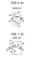
- Such a conventional differential epicyclic reduction gear mechanism as typically used in the art is constructed in a manner as shown in Fig. 1.
- the differential epicyclic reduction gear mechanism in each of Figs. 1 (a) and 1 (b) has an input shaft 10 and and output shaft 12 arranged at left and right sides thereof, respectively.
- the input shaft 10 has an eccentric shaft 14 connected thereto, on which an external gear 16 is rotatably mounted.
- the external gear 16 is meshed or engaged with an internal gear 18 fixedly mounted in a casing 20.
- the external gear 16 revolved round the input shaft 10 while revolving on its axis.
- the differential epicyclic reduction gear mechanism of Fig. 1 (a) constructed as described above is adapted to allow the rotation of the external gear 16 to drive an internal gear 22 mounted on the output shaft 12, whereas the differential epicyclic reduction gear mechanism shown in Fig. 1 (b) is adapted to carry out the transmission of rotation of the external gear 16 to the output shaft 12 by means of a universal joint 24.
- Such a differential epicyclic reduction gear mechanism constructed as described above has an advantage in as much as it is capable of achieving a large reduction ratio.
- the relationship of tooth number of the external gear 16 and that of the internal gear 18 to the reduction ratio will be indicated by the following equation (1):
- the rigid gear mechanism or differential epicyclic reduction gear mechanism shown in Fig. 1 has an important problem, in that it is substantially impossible to construct the mechanism in such a way as to reduce the difference in tooth number between the internal gear and the external gear because the mechanism has a relatively low contact ratio (i.e. the number of teeth intermeshing concurrently) and is highly subjected to restriction due to tooth profile interference.
- a mechanical reduction gear system comprising an external gear (16) which is rotatable about an ecentrically revolving shaft (14) and an internal ring gear (18) engaged with said external gear (16) characterised in that said external gear (16) has a tooth profile curve which is the combination of an addendum tooth profile curve outside the pitch circle and an epicycloid curve inside the pitch circle that is generated on the basis of a rolling or generating circle having a theoretical tooth number that is fewer by up to three than the tooth number of said pitch circle wherein said external gear (16) has a pressure angle (a e ) determined from the expression on said pitch circle and that said internal ring gear (18) has a tooth profile curve inside the pitch circle which is generated on the basis of the tooth profile of said external gear (16).
- the calculation of limitation of the tooth profile interference between an external gear and an internal gear may be. carried out on the basis of either a dedendum tooth profile of which a tooth profile curve is designed at the inside of a pitch point or an addendum tooth profile of which a tooth profile curve is designed at the outside thereof.
- the design of a tooth profile of a gear based on the dedendum tooth profile causes the tooth profile to be formed into a frusto-conical shape to significantly decrease the strength of the gear as compared with that of a bell-like shape obtained on the basis of the addendum tooth profile.
- the present invention has employed an addendum tooth profile.
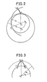
- Fig. 2 shows a principle of generating of an epicycloidic curve based on the rolling movement of a pitch circle.
- a pitch circle of an external gear having a radius of R, or pitch circle R which is initially contiguous to a pitch circle of an internal gear having a radius R 2 or pitch circle R 2 at a point P o carries out rolling movement, resulting in the contact point therebetween being changed from the point P o to a point P o and the initial contact point P o being moved to a position indicated by C in Fig. 2.
- an epicycloid curve Locus formed or generated by the point C when the rolling movement of the pitch circle R 2 of the internal gear is successively carried out on the assumption described above is called an epicycloid curve.
- a tooth profile curve of the external gear is at the outside of the epicycloid curve, a tooth profile point on the pitch circle R 2 of the internal gear must pass through the tooth portion of the external gear.
- interference or tooth profile interference Such a phenomenon is a so-called interference or tooth profile interference.
- the epicycloid curve provides an interference limiting line with respect to an addendum tooth profile of the external gear.
- such an epicycloid curve is named a limiting cycloid.
- a limiting cycloid curve as inside and outside tooth profile curves for the external gear allows the addendum tooth profile of the external gear to be obtained.
- Fig. 3 shows a model of a tooth profile of the external gear obtained using the limiting cycloid.
- an increase in absolute tooth number causes a reduction ratio to be increased.
- the tooth profile curve is desirably designed into a conical shape of which the inside and outside are symmetric with each other. In such an addendum curve as shown in Fig.
- a bottom curve at the inside of a tooth profile point E, on the pitch circle R may be formed by means of any suitable curve such as a circle arc, thus, the tooth profile curve is used to constitute only the portion between the pitch circle and an outer addendum circle of a radius R Al .
- An increase in tooth height (R Ai -R i ) causes an increase in contact ratio, thus it is desirable to decrease the thickness of the tooth top or the concentric portion of the addendum circle as much as possible.
- the design of rendering the thickness zero often interferes with the machining.
- the thickness is desirably decreased as much as possible, to the extent that hindrance does not occur.
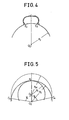
- a tooth profile curve of the internal curve contacting with that of the external gear is formed on the basis of only a point on the pitch circle R 2 . More particularly, as shown in Fig. 4, only a point E 2 on the tooth root is required to design the tooth profile curve.
- the remaining components required for the tooth profile curve are a tooth bottom curve formed in view of a relief and an inside concentric circle.
- phase angle ⁇ A of the intersection C A between the addendum circle and the pitch circle R 2 of the internal gear is expressed by the following equation (2):
- the contact ration e is calculated on the basis of the point E 2 on any one of both the inside and outside of the pitch circle of the internal gear within a range of ⁇ A according to the following equation (3):
- the formation of the tooth profile of the external gear using the limiting cycloid has a disadvantage that the tooth profile of the internal gear has a contact point which is not moved.
- it should be understood that it has an advantage of significantly increasing the contact ratio and substantially decreasing load burden of each tooth. Accordingly, it is desirable to design a tooth profile of an internal gear which is capable of effectively keeping the above-noted advantage and eliminating the above-described disadvantage.
- the tooth root of the limiting cycloid has a pressure angle of 0, accordingly, a decrease in a pressure angle a E at a point E on the epitrochoid curve allows the crossed axes angle between both curves at the point E to be reduced.
- the design is carried out to meet such requirements as indicated by the following equation (5): Then, relationships shown in Fig. 6 are considered.
- a distance from the center of a circle having a radius R G2 which rolls in contact with the circle R G1 to a point of which locus is to be obtained is indicated by R c , there are relationships therebetween which are indicated by the following equation (6): wherein R G2 is determined by preliminary determination of the radius of the addendum circle of the limiting cycloid and that of the epitrochoid curve to allow the pressure angles of both addendum circles to be substantially equal to each other.
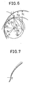
- the epitrochoid curve is obtained from the locus of a point C shown in Fig. 6 based on relationships indicated by the following equation (7):
- the so-designed tooth profile as shown in Fig. 7, has a curve which crosses the limiting cycloid curve indicated by dotted lines at a slight crossed axis angle at the point E on the tooth root and which moves gradually away from the limiting cycloid as it approaches the tooth top.
- the distance between both curves at the tooth top is very small, thus, it will be noted that it is readily carried out to design the tooth profile to allow the distance to be substantially equal to the deflection of the tooth during the actual loading operation.
- the tooth profile of the internal gear adapted to be engaged with the external gear having such a tooth profile as described above is obtained in the following matter.
- a gear is supposed which has an addendum circle of a radius larger than that of the gear designed as described above, and the rolling of the initially schemed pitch circles having radius of R 2 and R, is considered.
- the tooth profile of the pitch circle R 2 of the internal gear can be obtained by an envelope of the tooth profile of the pitch circle R, of the external gear which is formed by rolling the circle R 1 on the circle R 2 in Fig. 8.
- the tooth profile of the internal gear is designed which has an operating pitch circle comprising the pitch circle R, of the external gear passing through the tooth root of the addendum circle of the external gear and the pitch circle R 2 of the internal gear contiguous thereto.
- the tooth profile of the pitch circle R 1 of the external gear is formed to provide the tooth top with the concentric circle portion as shown in Fig. 3 and the addendum circle of a slightly larger radius is formed to have a sharp tooth top.
- the tooth profile curve of the internal gear may be generated to have a tooth profile having an operating pitch circle comprising pitch circles R,' and R 2 ' larger in radius respectively than the pitch circles R 1 , and R 2 which are substituted for the circles R 1 and R 2 .
- an operating pitch circle in the engagement between the first internal gear and the external gear comprises the pitch circles R 1 and R 2
- an operating pitch circle in the engagement between the second internal gear and the external gear comprises the pitch circles R,' and R 2 ' wherein R 1 '> R 1 , R 2 '> R 2
- a so-called magic gear mechanism is designed which allows two internal gears different in tooth number from each other, to be concurrently engaged with a single small gear.
- the present invention uses the epitrochoid curve with respect to the rolling circle or generating circle slightly smaller in radius than the pitch circle as a tooth profile curve and also uses the external gear of which the pressure angle is substantially minimum on the pitch circle. This allows the gear to be not only substantially increased in contact ratio in spite of being rigid but highly improved in operating contact under loading.
- the present invention can effectively provide a mechanical reduction gear system which is suitable for use for obtaining large output and substantial reduction.
Landscapes
- Engineering & Computer Science (AREA)
- General Engineering & Computer Science (AREA)
- Mechanical Engineering (AREA)
- Retarders (AREA)
- Gears, Cams (AREA)
Claims (5)

Applications Claiming Priority (2)
| Application Number | Priority Date | Filing Date | Title |
|---|---|---|---|
| JP65937/84 | 1984-04-04 | ||
| JP59065937A JPS60211146A (ja) | 1984-04-04 | 1984-04-04 | 歯車減速装置 |
Publications (2)
| Publication Number | Publication Date |
|---|---|
| EP0161072A1 EP0161072A1 (fr) | 1985-11-13 |
| EP0161072B1 true EP0161072B1 (fr) | 1988-09-21 |
Family
ID=13301371
Family Applications (1)
| Application Number | Title | Priority Date | Filing Date |
|---|---|---|---|
| EP85302449A Expired EP0161072B1 (fr) | 1984-04-04 | 1985-04-04 | Réducteur mécanique |
Country Status (3)
| Country | Link |
|---|---|
| EP (1) | EP0161072B1 (fr) |
| JP (1) | JPS60211146A (fr) |
| DE (1) | DE3565167D1 (fr) |
Cited By (1)
| Publication number | Priority date | Publication date | Assignee | Title |
|---|---|---|---|---|
| US7458433B2 (en) | 2003-07-31 | 2008-12-02 | Arvinmeritor Technology, Llc | Electric motor and gear drive assembly for driving a vehicle wheel |
Families Citing this family (5)
| Publication number | Priority date | Publication date | Assignee | Title |
|---|---|---|---|---|
| JP2639847B2 (ja) * | 1989-12-08 | 1997-08-13 | 住友重機械工業株式会社 | 遊星歯車増減速機 |
| KR20140128858A (ko) * | 2012-02-24 | 2014-11-06 | 니탄 밸브 가부시키가이샤 | 유성 기어 감속기 |
| CN105587842B (zh) * | 2016-03-24 | 2017-10-20 | 江苏理工学院 | 高强度低振动低噪声直齿轮传动机构 |
| FR3088398B1 (fr) * | 2018-11-08 | 2020-10-30 | Folly Abevi | Mecanisme de vis a rouleaux satellites |
| CN113446377B (zh) * | 2021-08-13 | 2023-03-10 | 天津大学 | 共轭摆线齿廓谐波减速器 |
Family Cites Families (3)
| Publication number | Priority date | Publication date | Assignee | Title |
|---|---|---|---|---|
| US2666336A (en) * | 1950-06-10 | 1954-01-19 | Hill Myron Francis | Internal gear teeth |
| FR1203942A (fr) * | 1958-07-30 | 1960-01-21 | Profil de deuture pour pignon et couronne dentée intérieurement, de diamètres voisins | |
| DE1775564A1 (de) * | 1967-08-30 | 1972-02-24 | Muneharu Morozumi | Schaltgetriebe mit einer Evolventenverzahnung |
-
1984
- 1984-04-04 JP JP59065937A patent/JPS60211146A/ja active Granted
-
1985
- 1985-04-04 EP EP85302449A patent/EP0161072B1/fr not_active Expired
- 1985-04-04 DE DE8585302449T patent/DE3565167D1/de not_active Expired
Cited By (1)
| Publication number | Priority date | Publication date | Assignee | Title |
|---|---|---|---|---|
| US7458433B2 (en) | 2003-07-31 | 2008-12-02 | Arvinmeritor Technology, Llc | Electric motor and gear drive assembly for driving a vehicle wheel |
Also Published As
| Publication number | Publication date |
|---|---|
| DE3565167D1 (en) | 1988-10-27 |
| EP0161072A1 (fr) | 1985-11-13 |
| JPS60211146A (ja) | 1985-10-23 |
| JPS6313057B2 (fr) | 1988-03-23 |
Similar Documents
| Publication | Publication Date | Title |
|---|---|---|
| JP3481335B2 (ja) | 内接噛合型遊星歯車装置 | |
| US4644814A (en) | Wide-angle gearing | |
| US6178840B1 (en) | Gear form constructions | |
| EP0266972B1 (fr) | Profil de dents de pièce cannelée d'un engrenage à onde | |
| US4974470A (en) | Tooth profile of one of circular splines of flat-shaped strain wave gearing | |
| US8776638B2 (en) | Wave gear device having three-dimensionally contactable shifted tooth profile | |
| JP2916012B2 (ja) | 波動歯車装置 | |
| US4155686A (en) | Hydrostatic intermeshing gear machine with substantially trochoidal tooth profile and one contact zone | |
| US4270401A (en) | Gear teeth | |
| EP0622566B1 (fr) | Engrenages de type a contact souple a profil de denture composite a deux arcs circulaires non decales | |
| US4850237A (en) | Tooth profile in meshing mechanism | |
| EP3306132B1 (fr) | Dispositif d'engrenage à ondes de déformation doté d'un engrènement composé impliquant la congruence des surfaces de dents | |
| WO1998045623A1 (fr) | Constructions de formes d'engrenage | |
| WO2001001020A1 (fr) | Transmission par engrenages cylindriques helicoidaux ou droits comportant de doubles surfaces de denture de pignon bombees et des surfaces de denture de roue conjuguees | |
| EP0161072B1 (fr) | Réducteur mécanique | |
| CN110848332B (zh) | 一种相交轴非圆面齿轮传动机构 | |
| WO2023015948A1 (fr) | Réducteur de vitesse harmonique présentant un profil de dent cycloïdal conjugué | |
| WO1980000365A1 (fr) | Engrenage de faible intensite sonore pour couple eleve | |
| EP0717819B1 (fr) | Engrenage a excentrique et procede de fabrication dudit engrenage | |
| EP3822511A1 (fr) | Transmission reductive a haut rapport | |
| US4382389A (en) | Rack and pinion gearing | |
| JPH0534537B2 (fr) | ||
| JPH05332404A (ja) | 撓み噛合い式歯車噛合構造 | |
| JPS61244966A (ja) | 歯車 | |
| US3946620A (en) | Gear with a trochoidal curved disk |
Legal Events
| Date | Code | Title | Description |
|---|---|---|---|
| PUAI | Public reference made under article 153(3) epc to a published international application that has entered the european phase |
Free format text: ORIGINAL CODE: 0009012 |
|
| AK | Designated contracting states |
Designated state(s): DE FR GB IT |
|
| 17P | Request for examination filed |
Effective date: 19860423 |
|
| 17Q | First examination report despatched |
Effective date: 19870715 |
|
| GRAA | (expected) grant |
Free format text: ORIGINAL CODE: 0009210 |
|
| AK | Designated contracting states |
Kind code of ref document: B1 Designated state(s): DE FR GB IT |
|
| PG25 | Lapsed in a contracting state [announced via postgrant information from national office to epo] |
Ref country code: IT Free format text: LAPSE BECAUSE OF FAILURE TO SUBMIT A TRANSLATION OF THE DESCRIPTION OR TO PAY THE FEE WITHIN THE PRESCRIBED TIME-LIMIT;WARNING: LAPSES OF ITALIAN PATENTS WITH EFFECTIVE DATE BEFORE 2007 MAY HAVE OCCURRED AT ANY TIME BEFORE 2007. THE CORRECT EFFECTIVE DATE MAY BE DIFFERENT FROM THE ONE RECORDED. Effective date: 19880921 Ref country code: FR Free format text: THE PATENT HAS BEEN ANNULLED BY A DECISION OF A NATIONAL AUTHORITY Effective date: 19880921 |
|
| REF | Corresponds to: |
Ref document number: 3565167 Country of ref document: DE Date of ref document: 19881027 |
|
| EN | Fr: translation not filed | ||
| PG25 | Lapsed in a contracting state [announced via postgrant information from national office to epo] |
Ref country code: GB Effective date: 19890404 |
|
| PLBE | No opposition filed within time limit |
Free format text: ORIGINAL CODE: 0009261 |
|
| STAA | Information on the status of an ep patent application or granted ep patent |
Free format text: STATUS: NO OPPOSITION FILED WITHIN TIME LIMIT |
|
| 26N | No opposition filed | ||
| GBPC | Gb: european patent ceased through non-payment of renewal fee | ||
| PGFP | Annual fee paid to national office [announced via postgrant information from national office to epo] |
Ref country code: DE Payment date: 19940408 Year of fee payment: 10 |
|
| PG25 | Lapsed in a contracting state [announced via postgrant information from national office to epo] |
Ref country code: DE Effective date: 19960103 |