EP0160283B1 - Heating system for rotating members - Google Patents
Heating system for rotating members Download PDFInfo
- Publication number
- EP0160283B1 EP0160283B1 EP85105107A EP85105107A EP0160283B1 EP 0160283 B1 EP0160283 B1 EP 0160283B1 EP 85105107 A EP85105107 A EP 85105107A EP 85105107 A EP85105107 A EP 85105107A EP 0160283 B1 EP0160283 B1 EP 0160283B1
- Authority
- EP
- European Patent Office
- Prior art keywords
- light
- temperature sensing
- article
- temperature
- strobe
- Prior art date
- Legal status (The legal status is an assumption and is not a legal conclusion. Google has not performed a legal analysis and makes no representation as to the accuracy of the status listed.)
- Expired
Links
Images

Classifications
-
- G—PHYSICS
- G01—MEASURING; TESTING
- G01N—INVESTIGATING OR ANALYSING MATERIALS BY DETERMINING THEIR CHEMICAL OR PHYSICAL PROPERTIES
- G01N21/00—Investigating or analysing materials by the use of optical means, i.e. using sub-millimetre waves, infrared, visible or ultraviolet light
- G01N21/01—Arrangements or apparatus for facilitating the optical investigation
- G01N21/03—Cuvette constructions
- G01N21/07—Centrifugal type cuvettes
-
- B—PERFORMING OPERATIONS; TRANSPORTING
- B04—CENTRIFUGAL APPARATUS OR MACHINES FOR CARRYING-OUT PHYSICAL OR CHEMICAL PROCESSES
- B04B—CENTRIFUGES
- B04B5/00—Other centrifuges
- B04B5/04—Radial chamber apparatus for separating predominantly liquid mixtures, e.g. butyrometers
- B04B5/0407—Radial chamber apparatus for separating predominantly liquid mixtures, e.g. butyrometers for liquids contained in receptacles
-
- B—PERFORMING OPERATIONS; TRANSPORTING
- B04—CENTRIFUGAL APPARATUS OR MACHINES FOR CARRYING-OUT PHYSICAL OR CHEMICAL PROCESSES
- B04B—CENTRIFUGES
- B04B13/00—Control arrangements specially designed for centrifuges; Program control of centrifuges
-
- B—PERFORMING OPERATIONS; TRANSPORTING
- B04—CENTRIFUGAL APPARATUS OR MACHINES FOR CARRYING-OUT PHYSICAL OR CHEMICAL PROCESSES
- B04B—CENTRIFUGES
- B04B15/00—Other accessories for centrifuges
- B04B15/02—Other accessories for centrifuges for cooling, heating, or heat insulating
-
- B—PERFORMING OPERATIONS; TRANSPORTING
- B04—CENTRIFUGAL APPARATUS OR MACHINES FOR CARRYING-OUT PHYSICAL OR CHEMICAL PROCESSES
- B04B—CENTRIFUGES
- B04B5/00—Other centrifuges
- B04B5/04—Radial chamber apparatus for separating predominantly liquid mixtures, e.g. butyrometers
Definitions
- This invention relates to a heating system, and more specifically to a method and apparatus for radiation heating of a rapidly rotating substrate.
- the sample processor card in accordance with the preferred embodiments as described in those copending applications, is an essentially closed container which is provided with a reagent used in the particular chemical test to be carried out and means for supplying a sample to the card.
- a reagent used in the particular chemical test to be carried out and means for supplying a sample to the card.
- the sample is inserted into the card and the card positioned in the holder on the centrifuge. Centrifugal force is thus used to release the reagent from its container in the card and displaces both the reagent and sample through the card for reaction as part of the chemical test as well as, in the preferred embodiments, to effect liquid- solid separation by centrifugation before the sample is contacted with the reagent.
- the product of the reaction is finally displaced to a cuvette chamber wherein the chemical reaction is determined, usually by optical means, to ascertain the results of the chemical test.
- the method and apparatus there disclosed is particularly well suited for use in the determination of blood chemistries. Because, however, the temperature at which the reaction between the sample and reagent is carried out should be controlled to achieve accurate results, it is necessary, in most cases, to heat the reagent and/ or sample to insure that they are within a relatively narrow temperature range. That heating operation is complex by reason of the fact that the centrifuge plate typically makes one revolution every 30 milliseconds, and thus supplying heating to the rapidly rotating card represents a difficult task. In addition, the centrifuge plate frequently carries a number of different cards atthe same time, each of which must be selectively heated from differing starting temperatures. It is not uncommon for the centrifuge plate to carry a number of cards, each of which is at a different temperature and all of which must be brought to the optimum temperature within a short period of time, typically one to two minutes.
- an apparatus for heating a rapid rotating article equipped with temperature sensing means comprising:
- a method for heating a rotating article having a temperature sensing and indicating element mounted thereon characterized in that it comprises the steps of:
- the concepts of the invention reside in a method and apparatus for heating a rapidly rotating article which includes a strobe light capable of emitting radiant energy which is positioned to radiate energy onto the article to be heated. Positioned on that article is a temperature sensing means rotating therewith, the temperature sensing means being adapted to reflect radiant energy as a function of its temperature.
- a light source is positioned to illuminate the temperature sensing means during rotation of the article and the light detector measures the changes in the light reflected by the temperature sensing means. If the temperature of the temperature sensing means is too low, a control circuit operatively connected to the detector causes the strobe light to be energized in synchronism with the rotation of the article to illuminate the article periodically, for example, during periodic rotations until the article is heated to the desired temperature.
- the article can be heated effectively, and that a number of articles rotating together can be individually and selectively heated.
- the concepts of the present invention are particularly well suited in the heating of chemical reagents present in sample processor cards used in accordance with the foregoing copending applications.
- the strobe can be pulsed for no longer than about 2 milliseconds during each revolution of the card with the plate. Since the temperature sensing means is associated with each card, each card can be selectively heated to bring it to the desired temperature, independent of the temperature of the other card.
- the centrifuge includes a plate member 10 which is mounted for rotation on an axis 12, and is driven by suitable drive means 14, preferably an electrical motor capable of operating at high speeds.
- suitable drive means 14 preferably an electrical motor capable of operating at high speeds.
- Mounted on the plate member 10 is at least one sample processor card holder 16 as described in published European patent application No. 0160901.
- the card holder 16 is akin to a tray and is rotatably mounted relative to the plate member 10 about an axis 18.
- the holder 16 can thus be rotated or indexed relative to the plate member 10 by suitable drive means not shown in the drawing for ease of description.
- the important feature is that the card holder 16 be adapted to receive the sample processor card and be rotatable relative to the plate member 10 so that the direction of centrifugal force acting on the sample processor card can be altered to effect the necessary fluid transport functions during the chemical testing operation.
- the centrifuge is also provided with a strobe light 20 surrounded by a reflector 22 as shown most clearly in Fig. 2 of the drawings.
- the strobe 20 can be positioned beneath the holder 16 to illuminate the lower portion of a sample processor card 24 as shown in Fig. 2 of the drawings.
- a light source 26 which is positioned to emit light through a lens 29 onto a portion of the sample processor card 16 during its rotation with the plate member 10 about the axis 12.
- a light detector 28 Positioned adjacent to the light source 26 is a light detector 28 which is positioned to receive light reflected from a portion of the sample processor card 24 through a lens 30, as will be described more fully hereinafter.
- the sample processor card includes means to introduce a sample to be analyzed, a supply of reagent and an overflow chamber to receive overflow sample inserted into the card. Sample is thus introduced into the card and moved through the various chambers defined therein by centrifugal force so that excess quantities of the sample introduced to the card flow into the overflow chamber.
- the sample and reagent are then mixed each with the other by centrifugal force acting in either the direction F o or F i , until the reaction product formed by the reagent and sample is moved to a cuvette or measuring chamber so that the necessary measurement on the reaction product can be carried out, usually by optical means.
- the cuvette chamber 32 which is more fully described in the foregoing copending application, is a chamber in which the optical characteristics of the reaction product between the reagent and the sample are measured by suitable optical techniques well known to those skilled in the art.
- the cuvette chamber has a lateral wall 34 onto which there is fixed a temperature sensing device 40.
- the temperature sensing device 40 Because of the proximity between the temperature sensing device 40 and the contents of the cuvette chamber 32, the temperature sensing device is essentially maintained at the temperature existing in the cuvette chamber 32. Since the exterior wall 34 is interior to the exterior wall 36, in the preferred embodiment of the invention of the card 24, there is provided a window 38 providing access to the temperature sensing device 40. Thus, the temperature sensing device 40 can be viewed through the window 38, as will be more fully described hereinafter.
- the sample processor card 24 is placed in the sample holder 16 so that the window 38 extends opposite to the axis of rotation 12 of the plate member 10.
- the temperature sensing means 40 has a temperature substantially the same as the contents of the cuvette chamber 32.
- the light source 26 illustrated in Fig. 1 is positioned to illuminate the temperature sensing means 40 during each rotation of the sample processor card. During that rotation, it emits a light pulse through lens 29 as the temperature sensing means 40 passes by.
- the temperature sensing means 40 is preferably a light sensing element, usually in the form of liquid crystal, whose light reflectivity changes as a function of temperature.
- the light detector 28 measures through lens 30 the intensity of the light reflected by the temperature sensing element 40 as a measure of the temperature of the contents of the cuvette cuvette chamber 32.
- Fig. 5 The details of the positional relationship between the light source 26 and the detector 28 relative to the temperature sensing element 40 carried by card 24 are shown in greater detail in Fig. 5 of the drawings.
- the light source 26 is positioned at an angle with respect to the temperature sensing means 40 so that direct reflected light leaving the temperature sensing element 40 follows a path away from the light detector 28.
- the light detector 28 as shown in Fig. 5 can be positioned out of the reflected light path so that it measures the change in reflectivity of the temperature sensing element 40, rather than the light directly reflected by it.
- the light source 26 is a light emitting diode or LED.
- LED's are preferred by reason of their long life, the fact that they emit a light source which is fairly monochromatic and the fact that they are a cool source of light imparting no substantial heat to the temperature sensing element 40.
- LED's can be pulsed for extremely short periods, for example, of the order of 300 microseconds and yet provide a fairly intense source of light.
- infrared LED's provide the best results, being brighter.
- use can also be made of a LED capable of emitting visible light.
- some detectors are more sensitive in the infrared reagion of the spectrum. The detector itself can be any of a variety of commercially available light detectors, the details of which form no part of the present invention.
- the control system is described in greater detail in Fig. 6 of the drawing.
- the light source 26 is positioned to illuminate a temperature sensing element 40 on the card, and the indirectly reflected light is detected by the light detector 28.
- the output from the light detector 28 is transmitted to an analog-to-digital converter 42 which converts the signal, synchronized with the rotation of the card on the centrifuge, to a digital signal which is processed by central processing unit 44 and a comparator 46. While the details of the analog-to-digital converter 42, the central processing unit 44 and the comparator 46 form no part of the present invention, the digitized signal is compared in the comparator with a signal representing a predetermined or threshold temperature which is programmed at the operator's discretion in the comparator 46.
- the comparator 46 If the reflectivity of the temperature sensing element 40 indicates that the temperature of the card on which the temperature sensing element is mounted is below the threshold temperature, then the comparator 46 generates a signal actuating a trigger 48 which in turn controls a power supply 50 to energize the strobe 20. If, on the other hand, the temperature of the card as indicated by the temperature sensing element 40 is at a temperature higher than the threshold temperature, then no signal is generated, and hence the strobe is not actuated during that revolution of the card.
- the illumination of the temperature sensing element 40 on the card by the light source 26 is synchronized with the spin rate of the plate so that each of a number of cards present on the rotating centrifuge can be individually examined by the light source 26 and the light detector 28 to determine their respective temperatures.
- the central processing unit can be programmed to monitor the rotational speed of the centrifuge so that a given card, when the temperature thereof is below the threshold temperature set in the comparator, is illuminated as it passes adjacent the strobe 20 after its temperature has been sensed by the detector 28.
- the central processing unit will, after detecting a temperature below the threshold temperature, delay energizing the strobe 75° for rotation so that the strobe is energized when that card bears the closest proximity to the strobe 20.
- the strobe itself shown schematically in Fig. 6 of the drawings, is preferably a xenon strobe light 52 which is surrounded by an ultraviolet absorbing coating 54 to absorb most of the ultraviolet radiation given off by the xenon light.
- an ultraviolet absorbing coating 54 to absorb most of the ultraviolet radiation given off by the xenon light.
- a sample processor card which contains a coating on the face opposite the xenon strobe to maximize absorption of the radiant energy given off by the strobe light.
- a sample processor card which contains a coating on the face opposite the xenon strobe to maximize absorption of the radiant energy given off by the strobe light.
- the card 24 itself is provided with a layer of adhesive 56 to secure to one face of the card a paper label 58.
- the adhesive is preferably formed of a light- absorbing material, and is preferably black in color to maximize the heat energy absorbed by the card to provide more efficient heating by the strobe light.
Landscapes
- Physics & Mathematics (AREA)
- Health & Medical Sciences (AREA)
- Life Sciences & Earth Sciences (AREA)
- Chemical & Material Sciences (AREA)
- Analytical Chemistry (AREA)
- Biochemistry (AREA)
- General Health & Medical Sciences (AREA)
- General Physics & Mathematics (AREA)
- Immunology (AREA)
- Pathology (AREA)
- Centrifugal Separators (AREA)
- Automatic Analysis And Handling Materials Therefor (AREA)
- Optical Measuring Cells (AREA)
- Investigating Or Analysing Materials By Optical Means (AREA)
- Control Of Temperature (AREA)
- Stroboscope Apparatuses (AREA)
- Control Of Resistance Heating (AREA)
Description
- This invention relates to a heating system, and more specifically to a method and apparatus for radiation heating of a rapidly rotating substrate.
- In published European patent applications Nos. 0160282 and 0160901 filed concurrently herewith there is described a method and apparatus for carrying out chemical testing in which an entire chemical test is effected on a rotating centrifuge. The centrifuge as disclosed in those copending applications is provided with a rotating plate on which there is mounted one or more sample processor card holders which rotate with the plate for generating centrifugal forces. The sample processor card holder mounted in such holders on the plate is rotatable relative to the plate to enable the direction in which the centrifuge force thus generated acts on a sample processor card positioned in the holder.
- The sample processor card, in accordance with the preferred embodiments as described in those copending applications, is an essentially closed container which is provided with a reagent used in the particular chemical test to be carried out and means for supplying a sample to the card. Thus, in use, the sample is inserted into the card and the card positioned in the holder on the centrifuge. Centrifugal force is thus used to release the reagent from its container in the card and displaces both the reagent and sample through the card for reaction as part of the chemical test as well as, in the preferred embodiments, to effect liquid- solid separation by centrifugation before the sample is contacted with the reagent.
- The product of the reaction is finally displaced to a cuvette chamber wherein the chemical reaction is determined, usually by optical means, to ascertain the results of the chemical test.
- As is described in theforegoing applications, the method and apparatus there disclosed is particularly well suited for use in the determination of blood chemistries. Because, however, the temperature at which the reaction between the sample and reagent is carried out should be controlled to achieve accurate results, it is necessary, in most cases, to heat the reagent and/ or sample to insure that they are within a relatively narrow temperature range. That heating operation is complex by reason of the fact that the centrifuge plate typically makes one revolution every 30 milliseconds, and thus supplying heating to the rapidly rotating card represents a difficult task. In addition, the centrifuge plate frequently carries a number of different cards atthe same time, each of which must be selectively heated from differing starting temperatures. It is not uncommon for the centrifuge plate to carry a number of cards, each of which is at a different temperature and all of which must be brought to the optimum temperature within a short period of time, typically one to two minutes.
- It is accordingly an object of the present invention to provide a method and apparatus for heating a rapidly rotating element.
- It is a more specific object of the invention to provide a method and apparatus for selectively heating each of a number of rotating elements carried on a centrifuge plate without contact between the heating device and the rotating element.
- It is another object of the invention to provide a method and apparatus for selectively heating a rotating chemical reaction vessel to control the temperature of the contents thereof.
- According to one aspect of the invention, these and other objects which will become apparent hereinafter are achieved by an apparatus for heating a rapid rotating article equipped with temperature sensing means comprising:
- (a) strobe means capable of emitting radiant energy and positioned to radiate energy into the article;
- (b) a light source positioned to illuminate temperature sensing means carried on the article during a portion of the rotation of the article, the temperature sensing means being adapted to reflect radiant energy as a function of the temperature of the article;
- (c) light detector means to detect changes in the light reflected from the temperature sensing means; and
- (d) control means to energize the strobe means in response to the light detector means whereby the light detector means sense light reflected by the temperature sensing means as a measure of the temperature on the article and energizes the strobe means to heat the article.
- According to another aspect of the invention, these and other objects are achieved by a method for heating a rotating article having a temperature sensing and indicating element mounted thereon, characterized in that it comprises the steps of:
- (a) illuminating the temperature sensing and indicating element with a light source,
- (b) measuring the change in light reflected from the temperature sensing and indicating element, wherein the temperature sensing and indicating means is adapted to reflect light as a function of the temperature of the article, and,
- (c) energizing a strobe light in response to the measurement of step (b) and in synchronism with the rotation of the article to radiate energy onto the article to heat the same.
- These and other objects and advantages of the invention will appear more fully hereinafter, and, for purposes of illustration but not of limitation, an embodiment of the invention is shown in the accompanying drawings where:
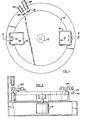
- Fig. 1 is a schematic top view of a centrifuge equipped with the heating system of the present invention;
- Fig. 2 is a sectional view taken along the lines 2-2 in Fig. 1;
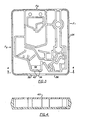
- Fig. 3 is a plan view illustrating a sample processor card employed in the practice of this invention;
- Fig. 4 is a sectional view taken along the lines 4-4 in Fig. 3;
- Fig. 5 is a schematic illustration of the light source and detector arrangement employed in the practice of this invention;
- Fig. 6 is a schematic view of the control system employed in the heating system of the invention.
- Fig. 7 is a side view in elevation of a preferred sample processor card used in the practice of the invention.
- The concepts of the invention reside in a method and apparatus for heating a rapidly rotating article which includes a strobe light capable of emitting radiant energy which is positioned to radiate energy onto the article to be heated. Positioned on that article is a temperature sensing means rotating therewith, the temperature sensing means being adapted to reflect radiant energy as a function of its temperature. A light source is positioned to illuminate the temperature sensing means during rotation of the article and the light detector measures the changes in the light reflected by the temperature sensing means. If the temperature of the temperature sensing means is too low, a control circuit operatively connected to the detector causes the strobe light to be energized in synchronism with the rotation of the article to illuminate the article periodically, for example, during periodic rotations until the article is heated to the desired temperature.
- It has been found, in accordance with the practice of the invention, that the article can be heated effectively, and that a number of articles rotating together can be individually and selectively heated.
- The concepts of the present invention are particularly well suited in the heating of chemical reagents present in sample processor cards used in accordance with the foregoing copending applications. For example, the strobe can be pulsed for no longer than about 2 milliseconds during each revolution of the card with the plate. Since the temperature sensing means is associated with each card, each card can be selectively heated to bring it to the desired temperature, independent of the temperature of the other card.
- Referring now to the drawings for a more detailed description of the invention, there is shown in Figs. 1 and 2 a centrifuge equipped with the heating system of the present invention. The centrifuge includes a plate member 10 which is mounted for rotation on an
axis 12, and is driven by suitable drive means 14, preferably an electrical motor capable of operating at high speeds. Mounted on the plate member 10 is at least one sampleprocessor card holder 16 as described in published European patent application No. 0160901. Thecard holder 16 is akin to a tray and is rotatably mounted relative to the plate member 10 about anaxis 18. Theholder 16 can thus be rotated or indexed relative to the plate member 10 by suitable drive means not shown in the drawing for ease of description. The important feature is that thecard holder 16 be adapted to receive the sample processor card and be rotatable relative to the plate member 10 so that the direction of centrifugal force acting on the sample processor card can be altered to effect the necessary fluid transport functions during the chemical testing operation. - The centrifuge is also provided with a
strobe light 20 surrounded by areflector 22 as shown most clearly in Fig. 2 of the drawings. Thestrobe 20 can be positioned beneath theholder 16 to illuminate the lower portion of asample processor card 24 as shown in Fig. 2 of the drawings. - Mounted adjacent to the rotatable plate 10 is a
light source 26 which is positioned to emit light through alens 29 onto a portion of thesample processor card 16 during its rotation with the plate member 10 about theaxis 12. Positioned adjacent to thelight source 26 is alight detector 28 which is positioned to receive light reflected from a portion of thesample processor card 24 through alens 30, as will be described more fully hereinafter. - A typical sample processor card used in the practice of this invention is described in detail in published European patent application No. 0160282 and is also illustrated in Figs. 3 and 4 of the drawings. The sample processor card includes means to introduce a sample to be analyzed, a supply of reagent and an overflow chamber to receive overflow sample inserted into the card. Sample is thus introduced into the card and moved through the various chambers defined therein by centrifugal force so that excess quantities of the sample introduced to the card flow into the overflow chamber. The sample and reagent are then mixed each with the other by centrifugal force acting in either the direction Fo or Fi, until the reaction product formed by the reagent and sample is moved to a cuvette or measuring chamber so that the necessary measurement on the reaction product can be carried out, usually by optical means. The
cuvette chamber 32, which is more fully described in the foregoing copending application, is a chamber in which the optical characteristics of the reaction product between the reagent and the sample are measured by suitable optical techniques well known to those skilled in the art. The cuvette chamber has alateral wall 34 onto which there is fixed atemperature sensing device 40. Because of the proximity between thetemperature sensing device 40 and the contents of thecuvette chamber 32, the temperature sensing device is essentially maintained at the temperature existing in thecuvette chamber 32. Since theexterior wall 34 is interior to the exterior wall 36, in the preferred embodiment of the invention of thecard 24, there is provided awindow 38 providing access to thetemperature sensing device 40. Thus, thetemperature sensing device 40 can be viewed through thewindow 38, as will be more fully described hereinafter. - In the preferred embodiment of the invention, the
sample processor card 24 is placed in thesample holder 16 so that thewindow 38 extends opposite to the axis ofrotation 12 of the plate member 10. After the manipulative steps, which are more fully described in the foregoing copending applications, have been carried out, and the reaction product of the sample and reagent are in the area of thecuvette chamber 32, the temperature sensing means 40 has a temperature substantially the same as the contents of thecuvette chamber 32. Thelight source 26 illustrated in Fig. 1 is positioned to illuminate the temperature sensing means 40 during each rotation of the sample processor card. During that rotation, it emits a light pulse throughlens 29 as the temperature sensing means 40 passes by. The temperature sensing means 40 is preferably a light sensing element, usually in the form of liquid crystal, whose light reflectivity changes as a function of temperature. Thus, thelight detector 28 measures throughlens 30 the intensity of the light reflected by thetemperature sensing element 40 as a measure of the temperature of the contents of thecuvette cuvette chamber 32. - The details of the positional relationship between the
light source 26 and thedetector 28 relative to thetemperature sensing element 40 carried bycard 24 are shown in greater detail in Fig. 5 of the drawings. In the preferred embodiment as shown in Fig. 5, thelight source 26 is positioned at an angle with respect to the temperature sensing means 40 so that direct reflected light leaving thetemperature sensing element 40 follows a path away from thelight detector 28. Thelight detector 28 as shown in Fig. 5 can be positioned out of the reflected light path so that it measures the change in reflectivity of thetemperature sensing element 40, rather than the light directly reflected by it. - In the preferred practice of the invention, the
light source 26 is a light emitting diode or LED. Such LED's are preferred by reason of their long life, the fact that they emit a light source which is fairly monochromatic and the fact that they are a cool source of light imparting no substantial heat to thetemperature sensing element 40. In addition, such LED's can be pulsed for extremely short periods, for example, of the order of 300 microseconds and yet provide a fairly intense source of light. In fact, in the one preferred embodiment of the invention, it has been found that infrared LED's provide the best results, being brighter. As an alternative, use can also be made of a LED capable of emitting visible light. Also, some detectors are more sensitive in the infrared reagion of the spectrum. The detector itself can be any of a variety of commercially available light detectors, the details of which form no part of the present invention. - The control system is described in greater detail in Fig. 6 of the drawing. As there described, the
light source 26 is positioned to illuminate atemperature sensing element 40 on the card, and the indirectly reflected light is detected by thelight detector 28. The output from thelight detector 28 is transmitted to an analog-to-digital converter 42 which converts the signal, synchronized with the rotation of the card on the centrifuge, to a digital signal which is processed bycentral processing unit 44 and acomparator 46. While the details of the analog-to-digital converter 42, thecentral processing unit 44 and thecomparator 46 form no part of the present invention, the digitized signal is compared in the comparator with a signal representing a predetermined or threshold temperature which is programmed at the operator's discretion in thecomparator 46. If the reflectivity of thetemperature sensing element 40 indicates that the temperature of the card on which the temperature sensing element is mounted is below the threshold temperature, then thecomparator 46 generates a signal actuating atrigger 48 which in turn controls apower supply 50 to energize thestrobe 20. If, on the other hand, the temperature of the card as indicated by thetemperature sensing element 40 is at a temperature higher than the threshold temperature, then no signal is generated, and hence the strobe is not actuated during that revolution of the card. - As will be appreciated by those skilled in the art, the illumination of the
temperature sensing element 40 on the card by thelight source 26 is synchronized with the spin rate of the plate so that each of a number of cards present on the rotating centrifuge can be individually examined by thelight source 26 and thelight detector 28 to determine their respective temperatures. By the same token, the central processing unit can be programmed to monitor the rotational speed of the centrifuge so that a given card, when the temperature thereof is below the threshold temperature set in the comparator, is illuminated as it passes adjacent thestrobe 20 after its temperature has been sensed by thedetector 28. For example, if thedetector 28 is positioned 75° of rotation before the position of the strobe light, the central processing unit will, after detecting a temperature below the threshold temperature, delay energizing the strobe 75° for rotation so that the strobe is energized when that card bears the closest proximity to thestrobe 20. - The strobe itself, shown schematically in Fig. 6 of the drawings, is preferably a
xenon strobe light 52 which is surrounded by anultraviolet absorbing coating 54 to absorb most of the ultraviolet radiation given off by the xenon light. Many of the chemical reactants employed in determining blood chemistries decompose in the presence of ultraviolet radiation, and hence the coating on the light is an effective measure to minimize such degradation. - In accordance with one preferred embodiment of the invention, it is sometimes desirable to employ a sample processor card which contains a coating on the face opposite the xenon strobe to maximize absorption of the radiant energy given off by the strobe light. One effective system for accomplishing that result is illustrated in Fig. 7 of the drawing. In that preferred embodiment, the
card 24 itself is provided with a layer of adhesive 56 to secure to one face of the card apaper label 58. The adhesive is preferably formed of a light- absorbing material, and is preferably black in color to maximize the heat energy absorbed by the card to provide more efficient heating by the strobe light. - Where technical features mentioned in any claim are followed by reference signs, those reference signs have been included for the sole purpose of increasing the intelligibility of the claims and accordingly, such reference signs do not have any limiting effect on the scope of each element identified by way of example by such reference signs.
Claims (10)
whereby the light detector means (28) sense light reflected by the temperature sensing means (40) as a measure of the temperature on the article (24) and energizes the strobe means (20) to heat the article (24).
Applications Claiming Priority (2)
| Application Number | Priority Date | Filing Date | Title |
|---|---|---|---|
| US606787 | 1984-05-03 | ||
| US06/606,787 US4632908A (en) | 1984-05-03 | 1984-05-03 | Heating system for rotating members |
Publications (3)
| Publication Number | Publication Date |
|---|---|
| EP0160283A2 EP0160283A2 (en) | 1985-11-06 |
| EP0160283A3 EP0160283A3 (en) | 1986-03-19 |
| EP0160283B1 true EP0160283B1 (en) | 1989-06-07 |
Family
ID=24429452
Family Applications (1)
| Application Number | Title | Priority Date | Filing Date |
|---|---|---|---|
| EP85105107A Expired EP0160283B1 (en) | 1984-05-03 | 1985-04-26 | Heating system for rotating members |
Country Status (5)
| Country | Link |
|---|---|
| US (1) | US4632908A (en) |
| EP (1) | EP0160283B1 (en) |
| JP (1) | JPS60238745A (en) |
| KR (1) | KR880001689B1 (en) |
| DE (1) | DE3570922D1 (en) |
Families Citing this family (47)
| Publication number | Priority date | Publication date | Assignee | Title |
|---|---|---|---|---|
| FR2572533B1 (en) * | 1984-10-26 | 1986-12-26 | Guigan Jean | METHOD FOR CARRYING OUT THE MEDICAL ANALYSIS OF A LIQUID SAMPLE USING AT LEAST ONE LIQUID REAGENT AND DEVICE FOR CARRYING OUT THE METHOD |
| FR2572534B1 (en) * | 1984-10-26 | 1986-12-26 | Guigan Jean | METHOD FOR CARRYING OUT THE MEDICAL ANALYSIS OF A LIQUID SAMPLE USING AT LEAST ONE DRY REAGENT, AND DEVICE FOR CARRYING OUT THE METHOD |
| US4711987A (en) * | 1985-03-01 | 1987-12-08 | Abbott Laboratories | Heat source circuitry for biological material analysis |
| USD292230S (en) | 1985-03-19 | 1987-10-06 | Abbott Laboratories | Sample processor card for use in chemical analysis apparatus |
| FR2592170B1 (en) * | 1985-12-20 | 1988-02-05 | Guigan Jean | METHOD AND DEVICE FOR DELIVERING A PREDETERMINED QUANTITY OF PLASMA FROM A BLOOD SAMPLE FOR ANALYSIS. |
| US4812294A (en) * | 1986-02-28 | 1989-03-14 | Automated Diagnostic Systems, Inc. | Specimen processing system |
| US4865810A (en) * | 1986-09-25 | 1989-09-12 | Kis Photo Industrie | Centrifuge for performing medical analyses |
| US4802772A (en) * | 1988-02-04 | 1989-02-07 | Westinghouse Electric Corp. | Nonelectric temperature monitor |
| IT1224633B (en) * | 1988-06-10 | 1990-10-04 | Instrumentation Lab Spa | HEATING DEVICE THERMOSTATATION OF CONTAINERS FOR BIOLOGICAL SAMPLES. |
| US5769540A (en) * | 1990-04-10 | 1998-06-23 | Luxtron Corporation | Non-contact optical techniques for measuring surface conditions |
| US5154512A (en) * | 1990-04-10 | 1992-10-13 | Luxtron Corporation | Non-contact techniques for measuring temperature or radiation-heated objects |
| US5310260A (en) * | 1990-04-10 | 1994-05-10 | Luxtron Corporation | Non-contact optical techniques for measuring surface conditions |
| US5061381A (en) * | 1990-06-04 | 1991-10-29 | Abaxis, Inc. | Apparatus and method for separating cells from biological fluids |
| JPH04137737U (en) * | 1991-06-21 | 1992-12-22 | 山形日本電気株式会社 | Movable heating table |
| US7133726B1 (en) | 1997-03-28 | 2006-11-07 | Applera Corporation | Thermal cycler for PCR |
| SE0001779D0 (en) * | 2000-05-12 | 2000-05-12 | Gyros Ab | Microanalysis device |
| US6349270B1 (en) | 1999-05-27 | 2002-02-19 | Emcore Corporation | Method and apparatus for measuring the temperature of objects on a fast moving holder |
| US6720187B2 (en) * | 2000-06-28 | 2004-04-13 | 3M Innovative Properties Company | Multi-format sample processing devices |
| US6734401B2 (en) * | 2000-06-28 | 2004-05-11 | 3M Innovative Properties Company | Enhanced sample processing devices, systems and methods |
| US6627159B1 (en) | 2000-06-28 | 2003-09-30 | 3M Innovative Properties Company | Centrifugal filling of sample processing devices |
| JP4773035B2 (en) * | 2000-06-28 | 2011-09-14 | スリーエム イノベイティブ プロパティズ カンパニー | Enhanced sample processing apparatus, system and method |
| US8097471B2 (en) | 2000-11-10 | 2012-01-17 | 3M Innovative Properties Company | Sample processing devices |
| US6889468B2 (en) | 2001-12-28 | 2005-05-10 | 3M Innovative Properties Company | Modular systems and methods for using sample processing devices |
| US6833536B2 (en) * | 2002-05-22 | 2004-12-21 | Applera Corporation | Non-contact radiant heating and temperature sensing device for a chemical reaction chamber |
| US7507376B2 (en) * | 2002-12-19 | 2009-03-24 | 3M Innovative Properties Company | Integrated sample processing devices |
| US7718133B2 (en) * | 2003-10-09 | 2010-05-18 | 3M Innovative Properties Company | Multilayer processing devices and methods |
| US7932090B2 (en) * | 2004-08-05 | 2011-04-26 | 3M Innovative Properties Company | Sample processing device positioning apparatus and methods |
| US7446288B2 (en) * | 2005-05-06 | 2008-11-04 | Applied Biosystems Inc. | Device including inductively heatable fluid retainment region, and method |
| US7754474B2 (en) | 2005-07-05 | 2010-07-13 | 3M Innovative Properties Company | Sample processing device compression systems and methods |
| USD564667S1 (en) | 2005-07-05 | 2008-03-18 | 3M Innovative Properties Company | Rotatable sample processing disk |
| US7763210B2 (en) | 2005-07-05 | 2010-07-27 | 3M Innovative Properties Company | Compliant microfluidic sample processing disks |
| US7323660B2 (en) | 2005-07-05 | 2008-01-29 | 3M Innovative Properties Company | Modular sample processing apparatus kits and modules |
| WO2008080049A2 (en) * | 2006-12-22 | 2008-07-03 | 3M Innovative Properties Company | Thermal transfer methods and structures for microfluidic systems |
| US20080152546A1 (en) * | 2006-12-22 | 2008-06-26 | 3M Innovative Properties Company | Enhanced sample processing devices, systems and methods |
| JP4614992B2 (en) * | 2007-07-27 | 2011-01-19 | パナソニック株式会社 | Analytical device, analytical apparatus and analytical method using the same |
| ES2640216T3 (en) | 2007-12-07 | 2017-11-02 | Miltenyi Biotec Gmbh | Systems and methods for cell processing |
| USD638550S1 (en) | 2009-11-13 | 2011-05-24 | 3M Innovative Properties Company | Sample processing disk cover |
| USD638951S1 (en) | 2009-11-13 | 2011-05-31 | 3M Innovative Properties Company | Sample processing disk cover |
| US8834792B2 (en) | 2009-11-13 | 2014-09-16 | 3M Innovative Properties Company | Systems for processing sample processing devices |
| USD667561S1 (en) | 2009-11-13 | 2012-09-18 | 3M Innovative Properties Company | Sample processing disk cover |
| WO2012158988A1 (en) | 2011-05-18 | 2012-11-22 | 3M Innovative Properties Company | Systems and methods for valving on a sample processing device |
| USD672467S1 (en) | 2011-05-18 | 2012-12-11 | 3M Innovative Properties Company | Rotatable sample processing disk |
| MX336625B (en) | 2011-05-18 | 2016-01-26 | 3M Innovative Properties Co | Systems and methods for volumetric metering on a sample processing device. |
| BR112013029181B1 (en) | 2011-05-18 | 2020-11-03 | Focus Diagnostics, Inc. | method and system for processing sample processing devices |
| EP2597153B1 (en) | 2011-11-25 | 2016-10-05 | Miltenyi Biotec GmbH | Cell separation method |
| US9630182B2 (en) | 2013-12-04 | 2017-04-25 | Leidos Innovations Technology, Inc. | Non-contact infrared thermocycling |
| GB201414666D0 (en) * | 2014-08-19 | 2014-10-01 | Colormatrix Holdings Inc | Polymeric materials |
Family Cites Families (10)
| Publication number | Priority date | Publication date | Assignee | Title |
|---|---|---|---|---|
| US3704625A (en) * | 1970-12-28 | 1972-12-05 | Sankyo Keiryoki | Thermometer using liquid crystal compositions |
| US3916152A (en) * | 1972-05-31 | 1975-10-28 | Union Carbide Corp | Temperature control system for a centrifugal-type chemistry analyzer |
| US3856470A (en) * | 1973-01-10 | 1974-12-24 | Baxter Laboratories Inc | Rotor apparatus |
| CH589319A5 (en) * | 1974-11-29 | 1977-06-30 | Hoffmann La Roche | |
| US4119834A (en) * | 1976-07-23 | 1978-10-10 | Joseph D. Losch | Electrical radiant heat food warmer and organizer |
| US4119381A (en) * | 1976-12-17 | 1978-10-10 | Eastman Kodak Company | Incubator and radiometric scanner |
| US4156626A (en) * | 1977-07-18 | 1979-05-29 | Souder James J | Method and apparatus for selectively heating discrete areas of surfaces with radiant energy |
| FR2409514A1 (en) * | 1977-11-17 | 1979-06-15 | Bretaudiere Jean Pierre | DEVELOPMENT OF CENTRIFUGATION ANALYSIS EQUIPMENT |
| GB1549584A (en) * | 1978-03-02 | 1979-08-08 | Standard Telephones Cables Ltd | Temperature responsive device |
| JPS5568638A (en) * | 1978-11-17 | 1980-05-23 | Chiyou Lsi Gijutsu Kenkyu Kumiai | Treating method of semiconductor surface with heat |
-
1984
- 1984-05-03 US US06/606,787 patent/US4632908A/en not_active Expired - Lifetime
-
1985
- 1985-04-26 EP EP85105107A patent/EP0160283B1/en not_active Expired
- 1985-04-26 DE DE8585105107T patent/DE3570922D1/en not_active Expired
- 1985-05-02 KR KR1019850002981A patent/KR880001689B1/en not_active Expired
- 1985-05-02 JP JP60093935A patent/JPS60238745A/en active Granted
Also Published As
| Publication number | Publication date |
|---|---|
| US4632908A (en) | 1986-12-30 |
| EP0160283A3 (en) | 1986-03-19 |
| KR880001689B1 (en) | 1988-09-06 |
| EP0160283A2 (en) | 1985-11-06 |
| JPS60238745A (en) | 1985-11-27 |
| JPH0352014B2 (en) | 1991-08-08 |
| DE3570922D1 (en) | 1989-07-13 |
| KR850008409A (en) | 1985-12-16 |
Similar Documents
| Publication | Publication Date | Title |
|---|---|---|
| US4632908A (en) | Heating system for rotating members | |
| US6833536B2 (en) | Non-contact radiant heating and temperature sensing device for a chemical reaction chamber | |
| JP4070222B2 (en) | Instrument for measuring near-infrared transmission spectrum of tablets | |
| CA1175672A (en) | Apparatus for monitoring chemical reactions | |
| US4808380A (en) | Automatic chemical analyzing apparatus | |
| JP2881826B2 (en) | Automatic analyzer | |
| CA1292627C (en) | Luminometer construction | |
| US4219529A (en) | Incubator for chemical analyzer | |
| US4420566A (en) | Method and apparatus for detecting sample fluid on an analysis slide | |
| US4778763A (en) | Analytical method and apparatus for determining fluorescence or phosphorescence | |
| EP0250671B1 (en) | Quantitative dispenser for a liquid | |
| US4710874A (en) | Method and apparatus for displaying particle sedimentation rates in liquids | |
| CA2204302C (en) | Spectrophotometric analysis | |
| JPS6327654B2 (en) | ||
| EP0087466B1 (en) | Method and apparatus for detecting sample fluid | |
| US4859420A (en) | Heating system for rotating members | |
| US5039225A (en) | Apparatus for measurement of reflection density | |
| JP2000180368A (en) | Chemical analyzer | |
| JPS6327661B2 (en) | ||
| JP2590688Y2 (en) | Blood coagulation analyzer | |
| EP0345882A1 (en) | Heating and temperature-control device for biological sample containers | |
| JP2001004318A (en) | Optical path length measurement device | |
| JPS6126861A (en) | Biochemical analyzing device | |
| JPH0710280Y2 (en) | Quantitative analyzer | |
| JPH045140B2 (en) |
Legal Events
| Date | Code | Title | Description |
|---|---|---|---|
| PUAI | Public reference made under article 153(3) epc to a published international application that has entered the european phase |
Free format text: ORIGINAL CODE: 0009012 |
|
| AK | Designated contracting states |
Designated state(s): BE CH DE FR GB IT LI NL SE |
|
| PUAL | Search report despatched |
Free format text: ORIGINAL CODE: 0009013 |
|
| RHK1 | Main classification (correction) |
Ipc: G01N 21/07 |
|
| AK | Designated contracting states |
Kind code of ref document: A3 Designated state(s): BE CH DE FR GB IT LI NL SE |
|
| 17P | Request for examination filed |
Effective date: 19860911 |
|
| 17Q | First examination report despatched |
Effective date: 19880215 |
|
| GRAA | (expected) grant |
Free format text: ORIGINAL CODE: 0009210 |
|
| AK | Designated contracting states |
Kind code of ref document: B1 Designated state(s): BE CH DE FR GB IT LI NL SE |
|
| ET | Fr: translation filed | ||
| REF | Corresponds to: |
Ref document number: 3570922 Country of ref document: DE Date of ref document: 19890713 |
|
| ITF | It: translation for a ep patent filed | ||
| PLBE | No opposition filed within time limit |
Free format text: ORIGINAL CODE: 0009261 |
|
| STAA | Information on the status of an ep patent application or granted ep patent |
Free format text: STATUS: NO OPPOSITION FILED WITHIN TIME LIMIT |
|
| 26N | No opposition filed | ||
| PGFP | Annual fee paid to national office [announced via postgrant information from national office to epo] |
Ref country code: FR Payment date: 19930412 Year of fee payment: 9 |
|
| ITTA | It: last paid annual fee | ||
| PGFP | Annual fee paid to national office [announced via postgrant information from national office to epo] |
Ref country code: CH Payment date: 19930611 Year of fee payment: 9 |
|
| PG25 | Lapsed in a contracting state [announced via postgrant information from national office to epo] |
Ref country code: LI Effective date: 19940430 Ref country code: CH Effective date: 19940430 |
|
| PG25 | Lapsed in a contracting state [announced via postgrant information from national office to epo] |
Ref country code: FR Effective date: 19941229 |
|
| REG | Reference to a national code |
Ref country code: CH Ref legal event code: PL |
|
| EAL | Se: european patent in force in sweden |
Ref document number: 85105107.8 |
|
| REG | Reference to a national code |
Ref country code: FR Ref legal event code: ST |
|
| REG | Reference to a national code |
Ref country code: GB Ref legal event code: IF02 |
|
| PGFP | Annual fee paid to national office [announced via postgrant information from national office to epo] |
Ref country code: GB Payment date: 20020315 Year of fee payment: 18 |
|
| PGFP | Annual fee paid to national office [announced via postgrant information from national office to epo] |
Ref country code: NL Payment date: 20020325 Year of fee payment: 18 |
|
| PGFP | Annual fee paid to national office [announced via postgrant information from national office to epo] |
Ref country code: SE Payment date: 20020405 Year of fee payment: 18 |
|
| PGFP | Annual fee paid to national office [announced via postgrant information from national office to epo] |
Ref country code: DE Payment date: 20020430 Year of fee payment: 18 |
|
| PGFP | Annual fee paid to national office [announced via postgrant information from national office to epo] |
Ref country code: BE Payment date: 20020523 Year of fee payment: 18 |
|
| PG25 | Lapsed in a contracting state [announced via postgrant information from national office to epo] |
Ref country code: GB Free format text: LAPSE BECAUSE OF NON-PAYMENT OF DUE FEES Effective date: 20030426 |
|
| PG25 | Lapsed in a contracting state [announced via postgrant information from national office to epo] |
Ref country code: SE Free format text: LAPSE BECAUSE OF NON-PAYMENT OF DUE FEES Effective date: 20030427 |
|
| PG25 | Lapsed in a contracting state [announced via postgrant information from national office to epo] |
Ref country code: BE Free format text: LAPSE BECAUSE OF NON-PAYMENT OF DUE FEES Effective date: 20030430 |
|
| BERE | Be: lapsed |
Owner name: *ABBOTT LABORATORIES Effective date: 20030430 |
|
| PG25 | Lapsed in a contracting state [announced via postgrant information from national office to epo] |
Ref country code: NL Free format text: LAPSE BECAUSE OF NON-PAYMENT OF DUE FEES Effective date: 20031101 Ref country code: DE Free format text: LAPSE BECAUSE OF NON-PAYMENT OF DUE FEES Effective date: 20031101 |
|
| NLV4 | Nl: lapsed or anulled due to non-payment of the annual fee |
Effective date: 20031101 |
|
| EUG | Se: european patent has lapsed | ||
| GBPC | Gb: european patent ceased through non-payment of renewal fee |