EP0160195A2 - Device for controlling the movements of a levelling blade of a ski track grooming vehicle - Google Patents
Device for controlling the movements of a levelling blade of a ski track grooming vehicle Download PDFInfo
- Publication number
- EP0160195A2 EP0160195A2 EP85103006A EP85103006A EP0160195A2 EP 0160195 A2 EP0160195 A2 EP 0160195A2 EP 85103006 A EP85103006 A EP 85103006A EP 85103006 A EP85103006 A EP 85103006A EP 0160195 A2 EP0160195 A2 EP 0160195A2
- Authority
- EP
- European Patent Office
- Prior art keywords
- snow
- vehicle
- controlling
- depth
- slope
- Prior art date
- Legal status (The legal status is an assumption and is not a legal conclusion. Google has not performed a legal analysis and makes no representation as to the accuracy of the status listed.)
- Granted
Links
Images

Classifications
-
- G—PHYSICS
- G01—MEASURING; TESTING
- G01S—RADIO DIRECTION-FINDING; RADIO NAVIGATION; DETERMINING DISTANCE OR VELOCITY BY USE OF RADIO WAVES; LOCATING OR PRESENCE-DETECTING BY USE OF THE REFLECTION OR RERADIATION OF RADIO WAVES; ANALOGOUS ARRANGEMENTS USING OTHER WAVES
- G01S15/00—Systems using the reflection or reradiation of acoustic waves, e.g. sonar systems
- G01S15/88—Sonar systems specially adapted for specific applications
-
- E—FIXED CONSTRUCTIONS
- E01—CONSTRUCTION OF ROADS, RAILWAYS, OR BRIDGES
- E01H—STREET CLEANING; CLEANING OF PERMANENT WAYS; CLEANING BEACHES; DISPERSING OR PREVENTING FOG IN GENERAL CLEANING STREET OR RAILWAY FURNITURE OR TUNNEL WALLS
- E01H4/00—Working on surfaces of snow or ice in order to make them suitable for traffic or sporting purposes, e.g. by compacting snow
- E01H4/02—Working on surfaces of snow or ice in order to make them suitable for traffic or sporting purposes, e.g. by compacting snow for sporting purposes, e.g. preparation of ski trails; Construction of artificial surfacings for snow or ice sports ; Trails specially adapted for on-the-snow vehicles, e.g. devices adapted for ski-trails
Definitions
- the invention relates to a device for controlling the movements of the Planicrwcrkzcuge of piste grooming vehicles.
- Slope grooming vehicles are used to prepare ski slopes so that they have no humps, icy areas and snow-free areas.
- the grooming vehicles are equipped with a dozer, generally with a dozer located on the front and pivotally connected to the vehicle, thereby controlling the vertical movements of the dozer.
- a pivotability of the dozer blade about a horizontal axis for controlling the angle of attack of the dozer blade relative to the snow surface, and a pivotability of the dozer blade about a vertical axis.
- the control of the dozer blade is in particular made more difficult by the fact that the up and down movements at the point of the slope grooming vehicle at which the dozer blade is pivoted are increasingly transmitted to the dozer blade according to the Lever Act.
- the known device is only functional in the desired manner on a substantially flat slope. If, for example, the dozer blade hits an uphill slope, it digs in because, due to the lack of pivoting of the support arms upwards when digging in, the desired orientation of the dozer blade does not occur in the position in which it rests with its convex surface.
- the object of the invention is to create a device with which the control of the leveling tools of piste grooming vehicles is simplified and which enables a better distribution of the amount of snow present on the ski slope.
- a particularly safe and problem-free control of the leveling tools is achieved if the reshaped output signals are fed directly to the device for controlling the leveling tool.
- a piste grooming vehicle 1 designed as a full-track vehicle has a driver's cab 2 and a dozer blade 3 on the front.
- the dozer blade 3 is attached to support arms 4 and 5, which are articulated on the front of the piste grooming vehicle 1 so as to be pivotable about a horizontal axis.
- Another device, not shown in the drawing, is provided for pivoting the dozer blade 3 about its horizontal longitudinal axis relative to the support arms 4 and 5, in order to adjust the angle of attack of the planic blade 3 relative to the slope surface, and also a device for pivoting the Dozer blade 3 around a vertical axis.
- the pivotable support arms 4 and 5 as well as the devices for adjusting the angle of attack of the dozer blade 1 or for pivoting the dozer blade 1 about a vertical axis are designed in a conventional manner and are preferably actuated hydraulically, the control by the driver being carried out in the cab 2 provided control device takes place.
- two electrical Mcban arrangements 6 and 7 are provided on the back of the dozer blade 3 of the pistol vehicle 1 for determining the depth of snow and possibly the type of snow.
- An ultrasound Mcb arrangement is preferably used.
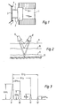
- an ultrasound transmitter 8 is provided, of which a part of the sound energy is reflected by the new snow surface 9, the old snow surface 10, the upper surface 11 of an ice layer and the bottom surface 12.
- the reflected sound energy components are picked up by an echo receiver 8 '.
- the pulse echo method can also be used, in which the same quartz alternately serves as the transmitter and receiver.
- a separate echo receiver is preferable.
- FIG. 3 shows the echoes measured by the echo receiver 8 'of the measuring arrangement according to FIG. 2 as a recording on a screen.
- the display of the echo 9 'with the intensity ⁇ A 1 ' touched by the reflection on the snow surface 9 after a running time ⁇ t 1 the echo 10 ', which corresponds to the surface 10 of the old snow layer and has an intensity ⁇ A 2 , after a running time ⁇ t 2 the echo 11 'of the surface 11 of the ice layer with an intensity ⁇ A 3 and as a last echo after a running time ⁇ t 3 the bottom echo 12' with the intensity 4 ⁇ 4 , the comes from the reflection on the floor surface 12.
- the thickness of the fresh snow can be obtained from the respective running time ⁇ t 1 , the thickness of the old snow layer from the running time ⁇ t 2 - ⁇ t 1, the thickness of the ice layer from the running time ⁇ t 3 - ⁇ t 2 and the from the running time ⁇ t 3 Total depth of the snow layer, including the ice layer.
- the intensity .DELTA.A 1 , .DELTA.A 2 and .DELTA.A 3 is dependent on the sound wave resistance and thus on the particular nature of the fresh snow or old snow or the ice layer.
- the output signals of this conversion device are fed to a display device, e.g. B. a board 13, as shown in Figure 4.
- a series of, for example, ten illuminated points a to j is provided, each of which corresponds to a snow depth difference of 10 cm with a total snow depth of one meter.
- all the luminous dots a to j light up when the snow depth is one meter or more, but z. B. only the illuminated points a to c at a snow depth of 30 to 40 cm.
- the color of the luminous dots a to j can be controlled so that the type of snow is reproduced, z. B. Blue for ice, yellow for old snow and green for fresh snow, so that, for. B. blue illuminated spots a to c, a yellow illuminated spot d and green illuminated spots e and f represent an ice layer of 30 to 40 cm, an old snow layer of 10 to 20 cm and a fresh snow layer of 20 to 30 cm.
- the driver can then actuate the control device for the dozer blade 3 provided in the cab 2 ...
- the output signals of the conversion device can also be fed directly to the control device for the dozer blade 3 in the piste grooming vehicle 1. In this way, the movements of the dozer 3 are automatically controlled so that at the same height of the lower edge of the dozer above the ground, d. H. the ground and any ice layer above it, the ski slope is leveled to a snow level that is as even as possible.
- the bottom echo 12 ' may be below the measurable limit.
- the snow depth to be leveled generally corresponds to the snow depth above the ice layer.
- a snow depth and possibly snow type measuring arrangement 6 and 7 is arranged on the left and right of the dozer blade 3.
- the measuring pulses obtained from the measuring arrangements 6 and 7 can be fed to the display panel 13 or directly to the control device for the dozer blade 3 via the forming device. Changes in snow depth and if necessary This compensates for the type of snow along the dozer blade 3. Instead, only one measuring device can preferably be arranged in the middle behind the dozer blade 3.
- the ultrasonic transmitter 8 can also be arranged such that it lies directly on the surface 9 of the uppermost layer of snow or is guided just below the snow surface 9, for example by an arrangement of the Ultrasonic transmitter 8 below the lower edge of the dozer blade 3 or on a carriage which guides the ultrasonic transmitter 8 in contact with the snow surface.
- another electrical measuring arrangement can also be provided according to the invention for determining the depth of snow and, if appropriate, type and thus for controlling the movements of the dozer blade 3.
- magnetic material such as iron filings
- the magnetic field strength can be determined with a magnetometer provided on the slope preparation vehicle 1, the magnetic field strength forming a measure of the depth of snow.
- radioactive material can be applied to the ground of the ski slope, with a counter tube being provided on the slope preparation vehicle 1, which measures the intensity of the radioactive radiation, on the basis of which the depth of snow can be determined.
- a measuring arrangement using radioactive radiation can be regarded as more than a theoretical, as a practically feasible option.
- Such an electrical measuring arrangement can also be provided, in which radio waves (VHF) are used.
- VHF signals are transmitted from a transmitter arranged on the piste grooming vehicle 1 at a certain angle obliquely to the snow surface, reflected by the ground and received by an antenna arranged on the piste vehicle 1.
- a series of antennas is preferably provided on the piste grooming vehicle and a fixed angle of incidence of the VHF signals or the reflection angle, so that the snow depth can be determined from the distance between the transmitter and the antenna receiving the VHF signal.
- a measuring arrangement with a high-power laser should be considered.
- the measuring arrangement is arranged on the piste grooming vehicle 1, which also carries the dozer blade 3 to be controlled.
- a separate snow groomer can also be provided, which has the measuring arrangement for determining the snow depth and possibly snow type and transmits the measured data to a snow grooming vehicle or a train from several snow grooming vehicles.
- This embodiment of the invention is explained in more detail below with reference to FIG. 5, which shows a section of a ski slope 14 in plan view.
- a snow groomer 15 which carries the measuring arrangement described in more detail above for determining the snow depth and possibly the type of snow. Furthermore, a locating device is installed to determine the respective location of the piste vehicle 15 departing from the ski slope 14.
- the locating device can be a radio locating device in which transmitters 16, 17, 18 and 19, which are arranged on "the ski slope 14, emit electrical waves or beacons which are received or are received by radio direction finders 20 arranged on the piste vehicle 15 electrical waves are emitted by transmitters located on the piste vehicle 15 and received here again in the form of a reflected signal.
- directional reception method in which the dependency of the antenna voltage on the direction of the electric waves incident from the transmitters 16 to 19 is used in the snow groomer 15, or the directional transmission method, in which are emitted by the transmitters 16 to 19 modulated electrical waves, the modulation representing the directional information
- radar methods for example a Radar transmission and reception device on the piste vehicle 15, wherein certain striking points on the ski slope 14, for example a boulder or a mountain top, are used for the location.
- the snow groomer 15 departing from the ski slope 14 thus creates an overall picture or cartographic representation of the snow depth and possibly snow type on the entire ski slope 14.
- the snow depth and type of snow are stored in a storage system 21 at each location of the snow groomer 15.
- the storage system 21 can, as shown in FIG. 5, be installed in a stationary manner, the data determined by the snow groomer 15 e.g. can be transmitted by radio to the storage system 21.
- the data collected with the storage system 21 are then evaluated by a computing system 22 for the entire ski slope 14.
- the data calculated by the computing system 22 are now passed on to the slope grooming vehicles, which are not shown in FIG. 5.
- zone A of ski slope 14 has a snow depth of 0.75 meters
- zone B has a snow depth of 0.50 meters
- zone C has a snow depth of 1.00 meters
- the slope grooming vehicles in Remove an average of 0.25 meters of snow from Zone C and thereby fill Zone B to obtain a substantially uniform snow depth of 0.75 meters on ski slope 14 if Zones C and B are the same size.
- the slope grooming vehicles can each have measuring arrangements for determining the Snow depth and, if appropriate, type of snow, as shown in FIG. 1, to take account of differences in the snow depth within the individual zones A, B and C, for example an icy brook 23 which extends below the snow cover over the ski slope 14.
- the movements of the dozer blade 3 of the piste grooming vehicles 1 can be controlled manually in accordance with the data transmitted by the computer system, and markings 24 can be provided at the edge of the piste at regular intervals, according to which the drivers of the piste grooming vehicles 1 orient themselves. Instead, these data can also be fed directly to the control device for actuating the dozer blade 3 of the individual slope grooming vehicles 1, i.e. automatic control can take place.
- the dozer blade can also be provided on the rear of the piste grooming vehicle 1.
- a snow blower can be arranged on the slope grooming vehicle 1 as a leveling tool, the latter being used in hard snow, e.g. artificial snow is preferred.
Abstract
Description
Die Erfindung bezieht sich auf eine Vorrichtung zur Steuerung der Bewegungen der Planicrwcrkzcuge von Pistenpräparicrfahrzeugen.The invention relates to a device for controlling the movements of the Planicrwcrkzcuge of piste grooming vehicles.
Mit Pistenpräparierfahrzeugen sollen Skipisten so hergerichtet werden, daß sie keine Buckel, vereiste Stellen und schneefreie Flächen aufweisen. Die Pistenpräparierfahrzeuge sind dazu mit einem Planierwerkzeug ausgerüstet, und zwar im allgemeinen mit einem an der Vorderseite angeordneten Planierschild, das mit dem Fahrzeug schwenkbar verbunden ist, wodurch die Vertikalbewegungen des Planierschildes gesteuert werden. Darüberhinaus ist im allgemeineneine Verschwenkbarkeit des Planierschildes um eine horizontale Achse zur Steuerung des Anstellwinkels des Planierschildes gegenüber der Schneeoberfläche sowie eine Verschwenkbarkeit des Planierschildes um eine Vertikalachse vorgesehen.Slope grooming vehicles are used to prepare ski slopes so that they have no humps, icy areas and snow-free areas. To this end, the grooming vehicles are equipped with a dozer, generally with a dozer located on the front and pivotally connected to the vehicle, thereby controlling the vertical movements of the dozer. In addition, there is generally a pivotability of the dozer blade about a horizontal axis for controlling the angle of attack of the dozer blade relative to the snow surface, and a pivotability of the dozer blade about a vertical axis.
Während bei der Präparierung einer ebenen Piste kaum Schwierigkeiten hinsichtlich der Steuerung der Bewegungen des Planierschildes auftreten, ergeben sich große Probleme bei der Ausrichtung des Planierschildes, wenn das Fahrzeug ein Gelände überfährt, das Buckel, abschüssige und ansteigende Strecken sowie Eisansammlungen unter der Schneeoberfläche aufweist.While there are hardly any difficulties with the preparation of a level runway with regard to controlling the movements of the dozer blade, there are great problems with the alignment of the dozer blade when the vehicle crosses a terrain that has humps, downhill and uphill sections and ice accumulations under the snow surface.
Hier werden große Anforderungen an den die Steuereinrichtung für das Planierschild betätigenden Fahrer des Pistenpräparierfahrzeuges gestellt. In.yielen Fällen ist es dabei unumgänglich, daß die Fahrgeschwindigkeit drastisch herabgesetzt wird, um die Bewegungen des Planierschildes steuern zu können.This places great demands on the driver of the snow groomer operating the control device for the dozer blade. In . In many cases, it is imperative that the driving speed is reduced drastically in order to be able to control the movements of the dozer blade.
Die Steuerung des Planierschildes wird nämlich insbesondere dadurch erschwert, daß die Auf- und Abbewegungen an der Stelle des Pistenpräparierfahrzeuges, an der das Planierschild verschwenkbar angelenkt ist, nach dem Hebelgesetz verstärkt auf das Planierschild übertragen werden.The control of the dozer blade is in particular made more difficult by the fact that the up and down movements at the point of the slope grooming vehicle at which the dozer blade is pivoted are increasingly transmitted to the dozer blade according to the Lever Act.
Doch selbst bei verminderter Fahrgeschwindigkeit besteht noch eine erhebliche Gefahr, daß das Planierschild sich in den Untergrund, also den Boden oder die den Boden bedeckende Eisschicht, eingräbt. So sind heutzutage selbst sehr erfahrene Fahrer von Pistenpräparierfahrzeugen schätzungsweise ein Viertel der Zeit damit beschäftigt, Schäden auf der Skipiste, die durch Eingraben des Planierschildes in den Untergrund entstanden sind, wieder auszubessern. Ein derartiges Eingraben kann freilich auch Beschädigungen des Fahrzeuges sowie gefährliche Unfälle zur Folge haben.However, even if the driving speed is reduced, there is still a considerable risk that the dozer blade will dig into the ground, ie the ground or the layer of ice covering the ground. Today, even very experienced drivers of snow grooming vehicles are estimated to be repairing a quarter of the time to repair damage on the ski slope caused by digging the dozer blade into the ground. Digging in this way can of course also result in damage to the vehicle and dangerous accidents.
Weiterhin treten meteorologisch bedingt innerhalb einer Saison erhebliche Schwankungen der Schneetiefe auf. Dies hat zur Folge, daß schneefreie Flächen auftreten können, die die Skipiste unbenutzbar machen. Wenn andererseits Schnee aus schneebedeckten Zonen der Skipiste mit einem Pistenpräparierfahrzeug zu einer solchen schneefreien Fläche geschoben wird, besteht die Gefahr, daß die Schneehöhe an der Stelle, an der der Schnee abgetragen wird, relativ gering ist und damit sofort oder bei Tauwetter nach kurzer Zeit eine neue schneefreie Stelle entsteht. Obwohl an sich auf der gesamten Skipiste noch genügend Schnee vorhanden wäre, um eine ausreichende Schneehöhe bei gleichmäßiger Schneeverteilung zu gewährleisten, muß also der Skibetrieb bereits eingestellt werden, wenn nur ein Bruchteil-der Skipiste schneefrei ist.Furthermore, due to the weather, considerable fluctuations in snow depth occur within one season. As a result, snow-free areas can occur which render the ski slope unusable. If, on the other hand, snow is pushed out of snow-covered areas of the ski slope with such a snow grooming vehicle to such a snow-free area, there is a risk that the snow depth at the point at which the snow is removed will be relatively low and thus immediately or after a short time in thawed weather new snow-free area is created. Although there would still be enough snow on the entire ski slope to ensure sufficient snow depth with even snow distribution afford, the ski operation must therefore already be stopped if only a fraction of the ski slope is snow-free.
Aus der europäischen Patentanmeldung mit der Veröffentlichungsnummer 0 082 450 ist eine Vorrichtung zur automatischen Steuerung des Planierschildes eines Pistenpräparierfahrzeuges bekannt. Dabei wird der Anstellwinkel des Planierschildes durch eine hydraulische Einrichtung in Abhängigkeit von den Schwenkbewegungen der Tragarme des Planierschildes so gesteuert, daß bei einer Bewegung der Tragarme nach unten bei einem Schneetal das Planierschild in der Weise ausgerichtet wird, daß es mit seiner konvexen Fläche auf dem Schnee aufliegt und sich damit nicht eingraben kann.From the European patent application with the
Die bekannte Vorrichtung ist jedoch nur bei einer im wesentlichen ebenen Piste in der gewünschten Weise funktionsfähig. Trifft beispielsweise das Planierschild auf einen ansteigenden Hang auf, so gräbt es sich ein, da mangels Verschwenkung der Tragarme nach oben beim Eingraben die angestrebte Ausrichtung des Planierschildes in die Lage, in der es mit seiner konvexen Fläche aufliegt, nicht eintritt.However, the known device is only functional in the desired manner on a substantially flat slope. If, for example, the dozer blade hits an uphill slope, it digs in because, due to the lack of pivoting of the support arms upwards when digging in, the desired orientation of the dozer blade does not occur in the position in which it rests with its convex surface.
Der Erfindung liegt demgegenüber die Aufgabe zugrunde, eine Vorrichtung zu schaffen, mit der die Steuerung der Planierwerkzeuge von Pistenpräparierfahrzeugen vereinfacht wird und die eine bessere Verteilung der auf der Skipiste vorhandenen Schneemenge ermöglicht.In contrast, the object of the invention is to create a device with which the control of the leveling tools of piste grooming vehicles is simplified and which enables a better distribution of the amount of snow present on the ski slope.
Diese Aufgabe wird gemäß der Erfindung mit den im kennzeichnenden Teil des Anspruchs 1 bzw. 3 angegebenen Merkmalen gelöst.This object is achieved according to the invention with the features specified in the characterizing part of
Eine besonders sichere und problemlose Steuerung der Planierwerkzeuge, selbst bei relativ hoher Geschwindigkeit, wird erreicht, wenn die umgeformten Ausgangssignale unmittelbar der Einrichtung zur Steuerung des Planierwerkzeuges zugeführt werden.A particularly safe and problem-free control of the leveling tools, even at a relatively high speed, is achieved if the reshaped output signals are fed directly to the device for controlling the leveling tool.
Ausführungsbeispiele der Erfindung werden nachstehend anhand der Zeichnung erläutert. Es zeigt:
- Figur 1 eine Draufsicht auf ein Pistonpräparierfahrzeug;
- Figur 2 eine Anordnung zur Bestimmung der Schneetiefe und Schneeart mit ultraschall;
Figur 3 die Wiedergabe einer Anzeige der Echos, die mit der Meßanordnung nach Figur 2 crhalten werden, auf einem Bildschirm;Figur 4 eine Tafel zur Anzeige der Schneetiefe und Schneeart; und- Figur 5 einen Pistenabschnitt in der Draufsicht.
- Figure 1 is a plan view of a piston preparation vehicle;
- Figure 2 shows an arrangement for determining the depth and type of snow with ultrasound;
- FIG. 3 shows a display of the echoes that are kept with the measuring arrangement according to FIG. 2 on a screen;
- FIG. 4 shows a board for displaying the depth and type of snow; and
- Figure 5 shows a slope section in plan view.
Gemäß Figur 1 weist ein als Vollkettenfahrzeug ausgebildetes Pistenpräparierfahrzeug 1 an der Vorderseite ein Fahrerhaus 2 sowie ein Planierschild 3 auf. Das Planierschild 3 ist an Tragarmen 4 und 5 befestigt, die an der Vorderseite des Pistenpräparierfahrzeuges 1 um eine waagrechte Achse verschwenkbar angelenkt sind. Eine weitere, in der Zeichnung nicht dargestellte Einrichtung ist zum Verschwenken des planierschildes 3 um seine waagrechte Längsachse gegenüber den Tragarmen 4 und 5 vorgesehen, um den Anstellwinkel des Planicrschildes 3 gegenüber der Pistenoberfläche einzustellen, ferner eine gleichfalls in der Zeichnung nicht dargestellte Einrichtung zum Verschwenken des Planierschildes 3 um eine senkrechte Achse.According to FIG. 1, a piste grooming vehicle 1 designed as a full-track vehicle has a driver's cab 2 and a
Die verschwenkbaren Tragarme 4 und 5 sowie die Einrichtungen zur Einstellung des Anstellwinkels des Planierschildes 1 bzw. zur Verschwenkung.des Planierschildes 1 um eine senkrechte Achse sind in herkömmlicher Weise ausgebildet und werden vorzugsweise hydraulisch betätigt, wobei die Steuerung durch den Fahrer mit einer im Fahrerhaus 2 vorgesehenen Steuereinrichtung erfolgt.The
An den einander gegenüberliegenden Enden sind an der Rückseite des Planierschildes 3 des Pistcnfahrzeuges 1 zwei elektrische Mcbanordnungen 6 und 7 zur Bestimmung der Schneetiefe und gegebenenfalls Schneeart vorgesehen. Dabei wird vorzugsweise eine Uitraschall-Mcbanordnung verwendet.At the opposite ends, two electrical Mcban arrangements 6 and 7 are provided on the back of the
Eine solche Ultraschall-Meßanordnung ist in Figur 2 detaillierter wiedergegeben. Dabei ist ein Ultraschall-Sender 8 vorgesehen, von dessen schallenergio jeweils ein Teil von der Neuschneooberfiäche 9, der Altschnceober- fläche 10, der Oherfläclie 11 einer Eisschicht und der Bodenoberfläche 12 reflektiert wird. Die reflektierten Schallenergie-Anteile werden von einem Echo-Empfänger 8' aufgenommen.Such an ultrasonic measuring arrangement is shown in more detail in FIG. In this case, an
Es braucht kein separater Echo-Empfänger 8' .vorzuliegen. Vielmehr kann auch das Impulsecho-Verfahren angewendet werden, bei dem derselbe Quarz alternierend als Sender und Empfänger dient. Jedoch ist z.B. bei einer Frequenz der Ultraschall-Wellen von 30.000 Hz oder weniger und einer Meßgenauigkeit von etwa 1 cm ein separater Echo-Empfänger vorzuziehen.There is no need for a separate echo receiver 8 '. Rather, the pulse echo method can also be used, in which the same quartz alternately serves as the transmitter and receiver. However, e.g. At a frequency of the ultrasonic waves of 30,000 Hz or less and a measuring accuracy of about 1 cm, a separate echo receiver is preferable.
In Figur 3 sind die von dem Echo-Empfänger 8' der Meßanordnung gemäß Figur 2 gemessenen Echos als Aufzeichnung auf einen Bildschirm wiedergegeben.FIG. 3 shows the echoes measured by the echo receiver 8 'of the measuring arrangement according to FIG. 2 as a recording on a screen.
Dabei sieht man auf dem Bildschirm zunächst die Anzeige des Echos 9' mit der Intensität △A1' das von der Reflexion an der Schneeoberfläche 9,berrührt, nach einer Laufzeit △ t1 das Echo 10', das der Oberfläche 10 der Altschneeschicht entspricht und eine Intcnsität △ A2 aufweist, nach einer Laufzeit △ t2 das Echo 11' der Oberfläche 11 der Eisschicht mit einer Intensität △ A3 und als letztes Echo nach einer Laufzeit △ t3 das Bodenecho 12' mit der Intensität 4 △4, das von der Reflexion an der Bodenoberfläche 12 stammt.Here you can see on the screen the display of the echo 9 'with the intensity △ A 1 ' touched by the reflection on the snow surface 9, after a running time △ t 1 the echo 10 ', which corresponds to the
Aus der jeweiligen Laufzeit Δ t1 kann die Dicke der Neuschneeschieht, aus der Laufzeit Δ t2 - Δ t1 die Dicke der Altschneeschicht, aus der Laufzeit Δ t3 -Δ t2 die Dicke der Eisschicht und aus der Laufzeit Δ t3 die Gesamttiefe der Schneeschicht, einschließlich der Eisschicht, bestimmt werden.The thickness of the fresh snow can be obtained from the respective running time Δ t 1 , the thickness of the old snow layer from the running time Δ t 2 - Δ t 1, the thickness of the ice layer from the running time Δ t 3 -Δ t 2 and the from the running time Δ t 3 Total depth of the snow layer, including the ice layer.
Weiterhin ist die Intensität Δ A1, Δ A2 und Δ A3 von dem Schallwellenwiderstand und damit von der jeweiligen Beschaffenheit des Neuschnees bzw. Altschnees bzw. der Eisschicht abhängig.Furthermore, the intensity .DELTA.A 1 , .DELTA.A 2 and .DELTA.A 3 is dependent on the sound wave resistance and thus on the particular nature of the fresh snow or old snow or the ice layer.
Die mit dem Echo-Empfänger 8' erhaltenen, in Figur 3 auf einen Bildschirm wiedergegebenen Meßimpulse (Δ A1, Δ A2, Δ A 3, Δ A4, Δ t1, Δ t2, Δ t3) werden einer Einrichtung zur Umformung der HeBimpulse zugeführt. Die Ausgangssignale dieser Umformungseinrichtung werden einer Anzeigeeinrichtung zugeführt, z. B. einer Tafel 13, wie sie in Figur 4 wiedergegeben ist. Dabei ist eine Reihe von beispielsweise zehn Leuchtpunkten a bis j vorgesehen, die jeweils einer Schneehöhendifferenz von 10 cm bei einer Gesamtschneehöhe von einem Meter entsprechen. D. h., es leuchten alle Leuchtpunkte a bis j auf, wenn die Schneehöhe einen Meter oder mehr beträgt, jedoch z. B. nur die Leuchtpunkte a bis c bei einer Schneehöhe von 30 bis 40 cm.The 8 'obtained, shown in figure 3 on a screen measuring pulses with the echo receiver (Δ A 1, Δ A 2, Δ A 3, Δ A 4, Δ t 1, Δ t 2, Δ t 3) of a device supplied for the shaping of the HeBimpulse. The output signals of this conversion device are fed to a display device, e.g. B. a
Gleichzeitig kann die Farbe der Leuchtpunkte a bis j so gesteuert werden, daß die Schneeart wiedergegeben wird, wobei z. B. Blau für Eis, Gelb für Altschnee und Grün für Neuschnee steht, so daß z. B. blaue Leuchtpunkte a bis c, ein gelber Leuchtpunkt d und grüne Leuchtpunkte e und f eine Eisschicht von 30 bis 40 cm, eine Altschneeschicht von 10 bis 20 cm und eine Neuschneeschicht von 20 bis 30 cm wiedergeben.At the same time, the color of the luminous dots a to j can be controlled so that the type of snow is reproduced, z. B. Blue for ice, yellow for old snow and green for fresh snow, so that, for. B. blue illuminated spots a to c, a yellow illuminated spot d and green illuminated spots e and f represent an ice layer of 30 to 40 cm, an old snow layer of 10 to 20 cm and a fresh snow layer of 20 to 30 cm.
Anhand der von der Anzeigetafel 13 angezeigten Schneehöhe und Schneeart kann dann der Fahrer die im Fahrerhaus 2 vorgesehene Steuereinrichtung für das Planierschild 3 betätigen...Using the snow depth and type of snow indicated by the
Statt der Anzeigetafel 13 können die Ausgangssignale der Umformungseinrichtung auch direkt der Steuereinrichtung für das Planierschild 3 im Pistenpräparierfahrzeug 1 zugeführt werden. Auf diese Weise werden die Bewegungen des Planierschildes 3 automatisch so gesteuert, daß bei gleicher Höhe der unteren Kante des Planierschildes über dem Untergrund, d. h. dem Erdboden und der gegebenenfalls darüber befindlichen Eisschicht, die Skipiste auf -eine möglichst gleichmäßige Schneehöhe planiert wird.Instead of the
Falls eine sehr harte Eisschicht vorliegt, kann das Bodenecho 12' unter Unständen unter der Meßbarkeitsgrenze liegen. Dies ist jedoch nicht weiter nachteilig, da die Schneehöhe, auf die planiert werden soll, in aller Regel der Schneehöhe über der Eisschicht entspricht.If there is a very hard layer of ice, the bottom echo 12 'may be below the measurable limit. However, this is not a further disadvantage, since the snow depth to be leveled generally corresponds to the snow depth above the ice layer.
In Figur 1 ist je eine Schneetiefe- und gegebenenfalls Schneeart-MeBanordnung 6 und 7 links und rechts am Planierschild 3 angeordnet. Die von den Meßanordnungen 6 und 7 erhaltenen Meßimpulse können über die Umformungseinrichtung gemittelt der Anzeigetafel 13 bzw. unmittelbar der Steuereinrichtung für das Planierschild 3 zugeführt werden. Änderungen der Schneehöhe und gegebenenfalls Schneeart entlang des Planierschildes 3 werden dadurch ausgeglichen. Stattdessen kann auch nur ein Meßgerät vorzugsweise in der Mitte hinter dem Planierschild 3 angeordnet sein.In Figure 1, a snow depth and possibly snow type measuring arrangement 6 and 7 is arranged on the left and right of the
Falls der Anteil der von der Oberfläche 9 der obersten Schneeschicht reflektierten Schallenergie so groß ist, also die Itensität Δ A1 des Echos 9', daß die darauffolgenden Intensitäten, und zwar. insbesondere die Intensität der Reflexion der Eisschicht Δ A3 nur noch schwer meßbar sind, kann der Ultraschallsender 8 auch so angeordnet werden, daß er unmittelbar auf der Oberfläche 9 der obersten Schneeschicht aufliegt oder knapp unter der Schneeoberfläche 9 geführt wird, beispielsweise durch eine Anordnung des Ultraschallsenders 8 unterhalb der Unterkante des Planierschildes 3 oder auf einem Schlitten, der den Ultraschallsender 8 in Berührung mit der Schneeoberfläche führt.If the proportion of the sound energy reflected from the surface 9 of the uppermost layer of snow is so large, ie the intensity Δ A 1 of the echo 9 ', that the following intensities, namely. In particular, the intensity of the reflection of the ice layer Δ A 3 can only be measured with difficulty, the
Statt einer Ultraschall-Meßanordnyng kann erfindungsgemäß auch eine andere elektrische-Meßanordnung zur Bestimmung der Schneetiefe und gegebenenfalls -art und damit zur Steuerung der Bewegungen des Planierschildes 3 vorgesehen sein.Instead of an ultrasonic measuring arrangement, another electrical measuring arrangement can also be provided according to the invention for determining the depth of snow and, if appropriate, type and thus for controlling the movements of the
Beispielsweise kann magnetisches Material, wie Eisenspäne, auf den Erdboden der Piste aufgebracht und dann mit einem am Pistenpräparierfahrzeug 1 vorgesehenen Magnetometer die magnetische Feldstärke bestimmt werden, wobei die magnetische Feldstärke ein Maß für die Schneetiefe bildet. Auch ist die Aufbringung von radioaktivem Material auf den Erdboden der Skipiste denkbar, wobei am Pistenpräparierfahrzeug 1 ein Zählrohr vorgesehen ist, das die Intensität der radioaktiven Strahlung mißt, anhand der sich die Schneetiefe ermitteln läßt. Allerdings ist im Hinblick auf die einschlägigen Vorschriften, insbesondere den Umweltschutz eine Meßanordnung unter Verwendung radioaktiver Strahlung mehr als eine theoretische, als eine praktisch durchführbare Möglichkeit anzusehen.For example, magnetic material, such as iron filings, can be applied to the ground of the slope and then the magnetic field strength can be determined with a magnetometer provided on the slope preparation vehicle 1, the magnetic field strength forming a measure of the depth of snow. It is also conceivable to apply radioactive material to the ground of the ski slope, with a counter tube being provided on the slope preparation vehicle 1, which measures the intensity of the radioactive radiation, on the basis of which the depth of snow can be determined. However, with regard to the relevant regulations, in particular environmental protection, a measuring arrangement using radioactive radiation can be regarded as more than a theoretical, as a practically feasible option.
Weiterhin kann eine solche elektrische Meßanordnung vorgesehen sein, bei der Radiowellen (UKW) verwendet werden. Dabei werden von einem am Pistenpräparierfahrzeug 1 angeordneten Sender mit einem bestimmten Winkel schräg zur Schneeoberfläche UKW-Signale ausgesendet, vom Boden reflektiert und von einer am Pistenfahrzeug 1 angeordneten Antenne empfangen. Vorzugsweise ist eine Serie von Antennen am Pistenpräparierfahrzeug und ein fester Einfallswinkel der UKW-Signale bzw. des Reflexionswinkels vorgesehen, so daß aus dem Abstand zwischen Sender und der das UKW-Signal empfangenden Antenne die Schneehöhe bestimmbar ist. Als weitere Meßanordnung ist eine Meßanordnung mit einem Hochleistungs-Laser in Erwägung zu ziehen.Such an electrical measuring arrangement can also be provided, in which radio waves (VHF) are used. In this case, VHF signals are transmitted from a transmitter arranged on the piste grooming vehicle 1 at a certain angle obliquely to the snow surface, reflected by the ground and received by an antenna arranged on the piste vehicle 1. A series of antennas is preferably provided on the piste grooming vehicle and a fixed angle of incidence of the VHF signals or the reflection angle, so that the snow depth can be determined from the distance between the transmitter and the antenna receiving the VHF signal. As a further measuring arrangement, a measuring arrangement with a high-power laser should be considered.
Bei der vorstehend beschriebenen Ausführungsform der Erfindung ist die Meßanordnung an dem Pistenpräparierfahrzeug 1 angeordnet, welches auch das zu steuernde Planierschild 3 trägt.In the embodiment of the Er described above The measuring arrangement is arranged on the piste grooming vehicle 1, which also carries the
Stattdessen kann jedoch auch ein separates Pistenfahrzeug vorgesehen sein, das die Meßanordnung zur Bestimmung der Schneehöhe und gegebenenfalls Schneeart aufweist und die gemessenen Daten an ein Pistenpräparierfahrzeug bzw. einen Zug aus mehreren Pistenpräparierfahrzeugen übermittelt. Diese Ausführungsform der Erfindung ist nachstehend anhand der Figur 5 näher erläutert, die einen Abschnitt einer Skipiste 14 in der Draufsicht zeigt.Instead, however, a separate snow groomer can also be provided, which has the measuring arrangement for determining the snow depth and possibly snow type and transmits the measured data to a snow grooming vehicle or a train from several snow grooming vehicles. This embodiment of the invention is explained in more detail below with reference to FIG. 5, which shows a section of a
Dabei ist ein Pistenfahrzeug 15 vorgesehen, das die vorstehend näher geschilderte Meßanordnung zur Bestimmung der Schneehöhe und gegebenenfalls Schneeart trägt. Weiterhin ist zur Bestimmung des jeweiligen Standorts des die Skipiste 14 abfahrenden Pistenfahrzeuges 15 eine Ortungseinrichtung installiert.In this case, a
Bei der Ortungseinrichtung kann es sich um eine Funkortungseinrichtung handeln, bei der Sender 16, 17, 18 und 19, die an" der Skipiste 14 angeordnet sind, elektrische Wellen oder Funkfeuer aussenden, die von am Pistenfahrzeug 15 angeordneten Funkpeilern 20 empfangen werden oder es werden von am Pistenfahrzeuq 15 befindlichen Sendern elektrische Wellen abgestrahlt und hier wiederum in Form eines reflektierten Signals empfangen.The locating device can be a radio locating device in which
Hierbei können im wesentlichen alle Verfahren und Vorrichtungen der Kurzstrecken-Funknavigation zum Einsatz kommen, z.B. das Richtempfangsverfahren, bei dem im Pistenfahrzeug 15 die Abhängigkeit der Antennenspannung von der Richtung der von den Sendern 16 bis 19 einfallenden elektrischen Wellen ausgenutzt wird, oder das Richtsendeverfahren, bei dem von den Sendern 16 bis 19 modulierte elektrische Wellen ausgesendet werden, wobei die Modulation die Richtungsinformation darstellt, ferner Radarverfahren, z.B. eine Radarsende- und Empfangseinrichtung am Pistenfahrzeug 15, wobei bestimmte markante Punkte an der Skipiste 14, z.B. ein Felsbrocken oder eine Bergkuppe, zur Ortung herangezogen werden.Essentially all methods and devices of short-range radio navigation can be used, e.g. the directional reception method, in which the dependency of the antenna voltage on the direction of the electric waves incident from the
Durch gleichzeitige Bestimmung der Schneetiefe und gegebenenfalls Schneeart einerseits und des Standorts des Pistenfahrzeuges 15 andererseits wird so durch das die Skipiste 14 abfahrende Pistenfahrzeug 15 eine Gesamtaufnahme oder kartografische Darstellung der Schneehöhe und gegebenenfalls Schneeart auf der gesamten Skipiste 14 erstellt.By simultaneously determining the snow depth and possibly snow type on the one hand and the location of the
Dazu werden Schneehöhe und Schneeart an jedem Standort des Pistenfahrzeuges 15 in einer Speicheranlage 21 abgespeichert. Die Speicheranlage 21 kann, wie in Figur 5 dargestellt, ortsfest installiert sein, wobei die von dem Pistenfahrzeug 15 ermittelten Daten z.B. per Funk an die Speicheranlage 21 übermittelt werden.For this purpose, the snow depth and type of snow are stored in a
Die mit der Speicheranlage 21 gesammelten Daten werden dann von einer Rechenanlage 22 für die gesamte Skipiste 14 ausgewertet. Die von der Rechenanlage 22 errechneten Daten werden nun an die Pistenpräparierfahrzeuge weitergegeben, die in Figur 5 nicht dargestellt sind.The data collected with the
Ist beispielsweise ermittelt worden, daß im Durchschnitt die Zone A der Skipiste 14 eine Schneehöhe von 0,75 Metern, die Zone B eine Schneehöhe von 0,50 Metern und die Zone C eine Schneehöhe von 1,00 Metern aufweist, so haben die Pistenpräparierfahrzeuge im Durchschnitt 0,25 Meter Schnee von der Zone C abzutragen und damit'die Zone B aufzufüllen, um eine im wesentlichen gleichmäßige Schneehöhe von 0, 75 Metern auf der Skipiste 14 zu erhalten, falls die Zonen C und B gleich groß sind.If, for example, it has been determined that on average zone A of
Selbstverständlich können die Pistenpräparierfahrzeuge ihrerseits jeweils mit Meßanordnungen zur Bestimmung der Schneehöhe und gegebenenfalls Schneeart ausgerüstet sein, wie in Figur 1 dargestellt, um Unterschiedenin der Schneehöhe innerhalb der einzelnen Zonen A, B und C Rechnung zu tragen, z.B. einem vereisten Bach 23, der sich unterhalb der Schneedecke über die Skipiste 14 erstreckt.Of course, the slope grooming vehicles can each have measuring arrangements for determining the Snow depth and, if appropriate, type of snow, as shown in FIG. 1, to take account of differences in the snow depth within the individual zones A, B and C, for example an
Die Steuerung der Bewegungen des Planierschildes 3 der Pistenpräparierfahrzeuge 1 entsprechend den von der Rechenanlage übermittelten Daten kann manuell erfolgen, wobei am Pistenrand in regelmäßigen Abständen Markierungen 24 vorgesehen sein können, nach denen sich die Fahrer der Pistenpräparierfahrzeuge 1 orientieren. Stattdessen können diese Daten'auch unmittelbar der Steuereinrichtung zur Betätigung des Planierschildes 3 der einzelnen Pistenpräparierfahrzeuge 1 zugeführt werden, d.h..es kann eine automatische Steuerung erfolgen.The movements of the
Das Planierschild kann im übrigen auch an der Rückseite des Pistenpräparierfahrzeuges 1 vorgesehen sein. Weiterhin kann als Planierwerkzeug eine Schneefräse am Pistenpräparierfahrzeug 1 angeordnet sein, wobei letztere bei hartem Schnee, z.B. künstlich erzeugtem Schnee bevorzugt verwendet wird.The dozer blade can also be provided on the rear of the piste grooming vehicle 1. Furthermore, a snow blower can be arranged on the slope grooming vehicle 1 as a leveling tool, the latter being used in hard snow, e.g. artificial snow is preferred.
Claims (5)
durch
eine elektrische Meßanordnung (6, 7) zur Bestimmung der Schneetiefe und gegebenenfalls Schneeart an einem die Skipiste (14) abfahrenden Pistenfahrzeug (15),
eine Ortungseinrichtung (16 bis 20) zur Bestimmung des jeweiligen Standorts des die Skipiste (14) abfahrenden Pistenfahrzeugs (15), und
eine Speicher- und Rechenanlage (21, 22), der die mit der Meßanordnung (6, 7)' erhaltenen Meßimpulse zusammen mit dem von der Ortungseinrichtung (16 bis 20) bestimmten jeweiligen Standort des Pistenfahrzeuges (15) zugeführt werden und die für jeden Standort der gesamten zu präparierenden Fläche der Skipiste (14) die optimale Schneehöhe anhand der eingegebenen Daten ermittelt und deren Ausgangssignale eine Anzeigevorrichtung und/oder unmittelbar einer Einrichtung zur Steuerung der Bewegung des Planierwerkzeugs (3) des oder der Pistenpräparierfahrzeuge (1) zugeführt werden.3. Device for controlling the movements of the leveling tools of grooming vehicles, marked
by
an electrical measuring arrangement (6, 7) for determining the depth of snow and, if appropriate, type of snow on a piste vehicle (15) departing the ski slope (14),
a locating device (16 to 20) for determining the respective location of the piste vehicle (15) departing from the ski slope (14), and
a storage and computing system (21, 22) to which the measuring pulses obtained with the measuring arrangement (6, 7) 'are fed together with the respective location of the snow groomer (15) determined by the locating device (16 to 20) and for each location of the entire area of the ski slope (14) to be groomed, the optimal snow depth is determined on the basis of the data entered and the output signals of which are fed to a display device and / or directly to a device for controlling the movement of the leveling tool (3) of the slope grooming vehicle (s) (1).
Priority Applications (1)
| Application Number | Priority Date | Filing Date | Title |
|---|---|---|---|
| AT85103006T ATE39146T1 (en) | 1984-05-02 | 1985-03-15 | DEVICE FOR CONTROLLING THE MOVEMENTS OF THE LEVELING TOOLS OF SLOPE GREEN VEHICLES. |
Applications Claiming Priority (2)
| Application Number | Priority Date | Filing Date | Title |
|---|---|---|---|
| DE3416246A DE3416246C1 (en) | 1984-05-02 | 1984-05-02 | Device for controlling the movements of the grading tools of snow groomer vehicles |
| DE3416246 | 1984-05-02 |
Publications (3)
| Publication Number | Publication Date |
|---|---|
| EP0160195A2 true EP0160195A2 (en) | 1985-11-06 |
| EP0160195A3 EP0160195A3 (en) | 1987-01-28 |
| EP0160195B1 EP0160195B1 (en) | 1988-12-07 |
Family
ID=6234809
Family Applications (1)
| Application Number | Title | Priority Date | Filing Date |
|---|---|---|---|
| EP85103006A Expired EP0160195B1 (en) | 1984-05-02 | 1985-03-15 | Device for controlling the movements of a levelling blade of a ski track grooming vehicle |
Country Status (3)
| Country | Link |
|---|---|
| EP (1) | EP0160195B1 (en) |
| AT (1) | ATE39146T1 (en) |
| DE (1) | DE3416246C1 (en) |
Cited By (9)
| Publication number | Priority date | Publication date | Assignee | Title |
|---|---|---|---|---|
| US5184293A (en) * | 1988-06-09 | 1993-02-02 | Spectra Physics | Apparatus for automatic depth control for earth moving and grading |
| US5235511A (en) * | 1988-06-09 | 1993-08-10 | Spectra-Physics, Inc. | Method for automatic depth control for earth moving and grading |
| EP0663474A1 (en) * | 1994-01-18 | 1995-07-19 | Gebr. Zaugg AG | Method for working a layer of snow or ice |
| FR2800454A1 (en) * | 1999-11-03 | 2001-05-04 | Meteo France | On ground snow thickness measuring wheel and carriage, with height sensor and anti-freeze spray for ensuring contact of wheel with ground surface |
| US7241908B2 (en) | 2004-05-11 | 2007-07-10 | Degussa Ag | Process for the direct synthesis of hydrogen peroxide |
| ITMI20092119A1 (en) * | 2009-12-01 | 2011-06-02 | Rolic Invest Sarl | VEHICLE BAPTIST AND ITS CONTROL METHOD |
| AT511770A1 (en) * | 2011-07-27 | 2013-02-15 | Set Software Engineering Tschuertz Gmbh | DEVICE FOR SNOW-MEASUREMENT MEASUREMENT |
| EP3633107A1 (en) * | 2018-10-05 | 2020-04-08 | Kässbohrer Geländefahrzeug AG | Ski trail maintenance vehicle and method for operating same |
| WO2022130279A1 (en) * | 2020-12-16 | 2022-06-23 | Prinoth S.P.A. | Snowgroomer and method for controlling a snowgroomer |
Families Citing this family (8)
| Publication number | Priority date | Publication date | Assignee | Title |
|---|---|---|---|---|
| FIU960089U0 (en) * | 1996-02-09 | 1996-02-09 | Kertzen Oy | Device for designing a snow plow |
| US5761095A (en) * | 1997-03-10 | 1998-06-02 | Rgs, Llc | System for monitoring the depth of snow |
| AU1847201A (en) * | 1999-11-30 | 2001-03-26 | Bombardier Inc. | Method and apparatus for snow depth mapping |
| AT410378B (en) * | 2000-08-21 | 2003-04-25 | Wintertechnik Engineering Gmbh | COMPUTER-CONTROLLED DEVICE FOR SNOWING AND MAINTAINING SKI SLOPES |
| DE10045524B4 (en) * | 2000-09-13 | 2004-05-27 | Kässbohrer Geländefahrzeug AG | Snow grooming device, snow grooming vehicle and method for operating a snow grooming device |
| US8428305B2 (en) | 2008-04-24 | 2013-04-23 | GM Global Technology Operations LLC | Method for detecting a clear path through topographical variation analysis |
| DE102009039716B3 (en) | 2009-08-28 | 2011-01-20 | Ruprecht-Karls-Universität Heidelberg | Measurement method for the nondestructive analysis of a snow coating and measuring device for carrying out the measuring method |
| DE102015208364A1 (en) * | 2015-05-06 | 2016-11-10 | Robert Bosch Gmbh | A method for determining properties of a ground on which a vehicle operable away from paved roads is moved |
Citations (9)
| Publication number | Priority date | Publication date | Assignee | Title |
|---|---|---|---|---|
| DE1067252B (en) * | 1959-10-15 | Heinrich Lanz Aktiengesellschaft, Mannheim | Automatic draft control device for attachments of agricultural implements | |
| FR1368133A (en) * | 1963-04-09 | 1964-07-31 | Saxby | ultrasonic snow depth measurement equipment |
| DE1457742A1 (en) * | 1965-12-28 | 1969-04-10 | Inst Hydraulik | Device for the regulation of intervals, especially for the depth regulation of tillage equipment |
| FR2124285A1 (en) * | 1971-02-01 | 1972-09-22 | Raytheon Co | |
| US4122429A (en) * | 1974-12-25 | 1978-10-24 | Tashiro Fukumoto | Apparatus for measuring water depth |
| DE3005259A1 (en) * | 1979-02-27 | 1980-09-04 | Precitec Gmbh | Electromagnetic system to determine take-off point of ski-jumper - has transmitter with induction coil in ski boot to produce HF signal picked up by receive coil adjacent to guide path ahead of jump |
| DE3128433A1 (en) * | 1981-07-18 | 1983-02-03 | Fried. Krupp Gmbh, 4300 Essen | Device for determining the position of an object, particularly a water craft |
| EP0082450A1 (en) * | 1981-12-17 | 1983-06-29 | Erich Prinoth | Device for the automatic blade-levelling of a track preparing machine in respect of the snow surface |
| JPS58158512A (en) * | 1982-03-16 | 1983-09-20 | Showa Electric Wire & Cable Co Ltd | Film thickness measuring device |
-
1984
- 1984-05-02 DE DE3416246A patent/DE3416246C1/en not_active Expired
-
1985
- 1985-03-15 AT AT85103006T patent/ATE39146T1/en not_active IP Right Cessation
- 1985-03-15 EP EP85103006A patent/EP0160195B1/en not_active Expired
Patent Citations (9)
| Publication number | Priority date | Publication date | Assignee | Title |
|---|---|---|---|---|
| DE1067252B (en) * | 1959-10-15 | Heinrich Lanz Aktiengesellschaft, Mannheim | Automatic draft control device for attachments of agricultural implements | |
| FR1368133A (en) * | 1963-04-09 | 1964-07-31 | Saxby | ultrasonic snow depth measurement equipment |
| DE1457742A1 (en) * | 1965-12-28 | 1969-04-10 | Inst Hydraulik | Device for the regulation of intervals, especially for the depth regulation of tillage equipment |
| FR2124285A1 (en) * | 1971-02-01 | 1972-09-22 | Raytheon Co | |
| US4122429A (en) * | 1974-12-25 | 1978-10-24 | Tashiro Fukumoto | Apparatus for measuring water depth |
| DE3005259A1 (en) * | 1979-02-27 | 1980-09-04 | Precitec Gmbh | Electromagnetic system to determine take-off point of ski-jumper - has transmitter with induction coil in ski boot to produce HF signal picked up by receive coil adjacent to guide path ahead of jump |
| DE3128433A1 (en) * | 1981-07-18 | 1983-02-03 | Fried. Krupp Gmbh, 4300 Essen | Device for determining the position of an object, particularly a water craft |
| EP0082450A1 (en) * | 1981-12-17 | 1983-06-29 | Erich Prinoth | Device for the automatic blade-levelling of a track preparing machine in respect of the snow surface |
| JPS58158512A (en) * | 1982-03-16 | 1983-09-20 | Showa Electric Wire & Cable Co Ltd | Film thickness measuring device |
Non-Patent Citations (1)
| Title |
|---|
| PATENTS ABSTRACTS OF JAPAN, Band 7, Nr. 282 (P-243)[1427], 16. Dezember 1983; & JP-A-58 158 512 (SHOWA DENSEN DENRAN K.K.) 20-09-1983 * |
Cited By (12)
| Publication number | Priority date | Publication date | Assignee | Title |
|---|---|---|---|---|
| US5184293A (en) * | 1988-06-09 | 1993-02-02 | Spectra Physics | Apparatus for automatic depth control for earth moving and grading |
| US5235511A (en) * | 1988-06-09 | 1993-08-10 | Spectra-Physics, Inc. | Method for automatic depth control for earth moving and grading |
| EP0663474A1 (en) * | 1994-01-18 | 1995-07-19 | Gebr. Zaugg AG | Method for working a layer of snow or ice |
| FR2800454A1 (en) * | 1999-11-03 | 2001-05-04 | Meteo France | On ground snow thickness measuring wheel and carriage, with height sensor and anti-freeze spray for ensuring contact of wheel with ground surface |
| US7241908B2 (en) | 2004-05-11 | 2007-07-10 | Degussa Ag | Process for the direct synthesis of hydrogen peroxide |
| ITMI20092119A1 (en) * | 2009-12-01 | 2011-06-02 | Rolic Invest Sarl | VEHICLE BAPTIST AND ITS CONTROL METHOD |
| WO2011067651A3 (en) * | 2009-12-01 | 2011-08-04 | Rolic Invest Sarl | Snow groomer and relative control method |
| US10329725B2 (en) | 2009-12-01 | 2019-06-25 | Prinoth S.P.A. | Snow groomer and relative control method |
| AT511770A1 (en) * | 2011-07-27 | 2013-02-15 | Set Software Engineering Tschuertz Gmbh | DEVICE FOR SNOW-MEASUREMENT MEASUREMENT |
| AT511770B1 (en) * | 2011-07-27 | 2015-03-15 | Set Software Engineering Tschürtz Gmbh | DEVICE FOR SNOW-MEASUREMENT MEASUREMENT |
| EP3633107A1 (en) * | 2018-10-05 | 2020-04-08 | Kässbohrer Geländefahrzeug AG | Ski trail maintenance vehicle and method for operating same |
| WO2022130279A1 (en) * | 2020-12-16 | 2022-06-23 | Prinoth S.P.A. | Snowgroomer and method for controlling a snowgroomer |
Also Published As
| Publication number | Publication date |
|---|---|
| DE3416246C1 (en) | 1985-10-24 |
| EP0160195B1 (en) | 1988-12-07 |
| ATE39146T1 (en) | 1988-12-15 |
| EP0160195A3 (en) | 1987-01-28 |
Similar Documents
| Publication | Publication Date | Title |
|---|---|---|
| EP0160195B1 (en) | Device for controlling the movements of a levelling blade of a ski track grooming vehicle | |
| EP0660660B1 (en) | Process for working exploitable territories | |
| DE69633453T2 (en) | Spreading systems and methods | |
| DE69720022T2 (en) | METHOD AND DEVICE FOR DETERMINING THE POSITION AND SPEED OF A VEHICLE | |
| EP3623533B1 (en) | Cable handling apparatus and method | |
| EP1818456B1 (en) | Method of guiding a piste maintenance vehicle and piste maintenance vehicle | |
| DE2708686B2 (en) | Method and device for automatically guiding an object relative to a predetermined path | |
| EP2198688A1 (en) | Method for controlling the compaction of agricultural goods in a driving or horizontal silo and compaction vehicle | |
| DE102018217049A1 (en) | Snow grooming vehicle and method for operating a snow grooming vehicle | |
| DE19956943A1 (en) | Device for controlling the compaction in vibration compaction devices | |
| DE3938147C2 (en) | Procedure for controlling spreaders for winter service | |
| DE2346944A1 (en) | METHOD OF CONTROLLING A ROAD CONSTRUCTION MACHINE | |
| DE2449127A1 (en) | BUMPER | |
| EP1182409B1 (en) | Computer controlled equipment for maintaining and covering skiing slopes with snow | |
| EP1536067B1 (en) | Road slipperness prevention wherein the quantity of spread material is adapted to the variable temperature of the ground | |
| EP3707984B1 (en) | Device for producing a ground profile for promoting germination and establishment of seedling and plant in forestry | |
| AT510621A1 (en) | LOOSE CARE INSTRUMENT FOR AGRICULTURAL VEHICLES | |
| Lever et al. | Mobility of cargo trains during year two of the proof-of-concept South Pole Traverse | |
| Roby et al. | Mechanical methods of chaparral modification | |
| AT500147B1 (en) | GPS SUPPORTED PISTON CAR | |
| DE102017213925A1 (en) | A road condition information acquisition method, traffic information distribution method, and a traffic information system | |
| DE19716002A1 (en) | Motor vehicle radar arrangement | |
| DE19838199C1 (en) | Soil sampling drill | |
| DE3333445A1 (en) | Method for determining the position of a pipe laid in the ground | |
| EP0804745B1 (en) | Process and device for non-contact measurement of speed on surfaces |
Legal Events
| Date | Code | Title | Description |
|---|---|---|---|
| PUAI | Public reference made under article 153(3) epc to a published international application that has entered the european phase |
Free format text: ORIGINAL CODE: 0009012 |
|
| AK | Designated contracting states |
Designated state(s): AT CH FR IT LI SE |
|
| 17P | Request for examination filed |
Effective date: 19860324 |
|
| PUAL | Search report despatched |
Free format text: ORIGINAL CODE: 0009013 |
|
| AK | Designated contracting states |
Kind code of ref document: A3 Designated state(s): AT CH FR IT LI SE |
|
| 17Q | First examination report despatched |
Effective date: 19880127 |
|
| RAP1 | Party data changed (applicant data changed or rights of an application transferred) |
Owner name: SKI-DATA COMPUTERHANDELSGESELLSCHAFT M.B.H. |
|
| GRAA | (expected) grant |
Free format text: ORIGINAL CODE: 0009210 |
|
| AK | Designated contracting states |
Kind code of ref document: B1 Designated state(s): AT CH FR IT LI SE |
|
| REF | Corresponds to: |
Ref document number: 39146 Country of ref document: AT Date of ref document: 19881215 Kind code of ref document: T |
|
| ITF | It: translation for a ep patent filed |
Owner name: ING. PIOVESANA PAOLO |
|
| ET | Fr: translation filed | ||
| RAP2 | Party data changed (patent owner data changed or rights of a patent transferred) |
Owner name: SKIDATA COMPUTER GESELLSCHAFT M.B.H. |
|
| REG | Reference to a national code |
Ref country code: CH Ref legal event code: PFA Free format text: SKIDATA COMPUTER GESELLSCHAFT M.B.H. |
|
| PLBE | No opposition filed within time limit |
Free format text: ORIGINAL CODE: 0009261 |
|
| STAA | Information on the status of an ep patent application or granted ep patent |
Free format text: STATUS: NO OPPOSITION FILED WITHIN TIME LIMIT |
|
| 26N | No opposition filed | ||
| ITTA | It: last paid annual fee | ||
| EAL | Se: european patent in force in sweden |
Ref document number: 85103006.4 |
|
| PGFP | Annual fee paid to national office [announced via postgrant information from national office to epo] |
Ref country code: AT Payment date: 19950314 Year of fee payment: 11 |
|
| PGFP | Annual fee paid to national office [announced via postgrant information from national office to epo] |
Ref country code: SE Payment date: 19950315 Year of fee payment: 11 |
|
| PGFP | Annual fee paid to national office [announced via postgrant information from national office to epo] |
Ref country code: FR Payment date: 19950316 Year of fee payment: 11 |
|
| PGFP | Annual fee paid to national office [announced via postgrant information from national office to epo] |
Ref country code: CH Payment date: 19950323 Year of fee payment: 11 |
|
| PG25 | Lapsed in a contracting state [announced via postgrant information from national office to epo] |
Ref country code: AT Effective date: 19960315 |
|
| PG25 | Lapsed in a contracting state [announced via postgrant information from national office to epo] |
Ref country code: SE Effective date: 19960316 |
|
| PG25 | Lapsed in a contracting state [announced via postgrant information from national office to epo] |
Ref country code: LI Effective date: 19960331 Ref country code: CH Effective date: 19960331 |
|
| REG | Reference to a national code |
Ref country code: CH Ref legal event code: PL |
|
| PG25 | Lapsed in a contracting state [announced via postgrant information from national office to epo] |
Ref country code: FR Effective date: 19961129 |
|
| EUG | Se: european patent has lapsed |
Ref document number: 85103006.4 |
|
| REG | Reference to a national code |
Ref country code: FR Ref legal event code: ST |