EP0159984B1 - Trennkupplung für schlauchleitungen - Google Patents
Trennkupplung für schlauchleitungen Download PDFInfo
- Publication number
- EP0159984B1 EP0159984B1 EP84900080A EP84900080A EP0159984B1 EP 0159984 B1 EP0159984 B1 EP 0159984B1 EP 84900080 A EP84900080 A EP 84900080A EP 84900080 A EP84900080 A EP 84900080A EP 0159984 B1 EP0159984 B1 EP 0159984B1
- Authority
- EP
- European Patent Office
- Prior art keywords
- coupling
- break
- members
- valve
- fluid
- Prior art date
- Legal status (The legal status is an assumption and is not a legal conclusion. Google has not performed a legal analysis and makes no representation as to the accuracy of the status listed.)
- Expired
Links
Images

Classifications
-
- B—PERFORMING OPERATIONS; TRANSPORTING
- B63—SHIPS OR OTHER WATERBORNE VESSELS; RELATED EQUIPMENT
- B63B—SHIPS OR OTHER WATERBORNE VESSELS; EQUIPMENT FOR SHIPPING
- B63B27/00—Arrangement of ship-based loading or unloading equipment for cargo or passengers
- B63B27/24—Arrangement of ship-based loading or unloading equipment for cargo or passengers of pipe-lines
-
- F—MECHANICAL ENGINEERING; LIGHTING; HEATING; WEAPONS; BLASTING
- F16—ENGINEERING ELEMENTS AND UNITS; GENERAL MEASURES FOR PRODUCING AND MAINTAINING EFFECTIVE FUNCTIONING OF MACHINES OR INSTALLATIONS; THERMAL INSULATION IN GENERAL
- F16L—PIPES; JOINTS OR FITTINGS FOR PIPES; SUPPORTS FOR PIPES, CABLES OR PROTECTIVE TUBING; MEANS FOR THERMAL INSULATION IN GENERAL
- F16L55/00—Devices or appurtenances for use in, or in connection with, pipes or pipe systems
- F16L55/10—Means for stopping flow from or in pipes or hoses
- F16L55/1007—Couplings closed automatically when broken
-
- Y—GENERAL TAGGING OF NEW TECHNOLOGICAL DEVELOPMENTS; GENERAL TAGGING OF CROSS-SECTIONAL TECHNOLOGIES SPANNING OVER SEVERAL SECTIONS OF THE IPC; TECHNICAL SUBJECTS COVERED BY FORMER USPC CROSS-REFERENCE ART COLLECTIONS [XRACs] AND DIGESTS
- Y10—TECHNICAL SUBJECTS COVERED BY FORMER USPC
- Y10T—TECHNICAL SUBJECTS COVERED BY FORMER US CLASSIFICATION
- Y10T137/00—Fluid handling
- Y10T137/1624—Destructible or deformable element controlled
- Y10T137/1632—Destructible element
- Y10T137/1654—Separable valve coupling or conduit
Definitions
- This invention relates to so-called break-away couplings for incorporation in hoselines, pipe-lines or the like, to minimise or eliminate spillage in the event of breaking of the line.
- a break-away coupling device for use with a hoseline or pipeline, comprising a first coupling member of generally tubular form for connection at its one end to a hoseline, pipeline or other fluid-supply or fluid-delivery point, and provided at its other end with a face to be held in sealing engagement with a complementary face of a second coupling member; frangible means holding said faces in sealing engagement; said first coupling member further comprising a valve seat and a valve member, and spring means urging the valve member towards closing engagement with said seat but the valve member usually being held against said spring means out of engagement with the valve seat until said coupling members are separated on breaking of the frangible means; characterised by piston means to apply pressure between said coupling members which will break said frangible means and separate said faces and said coupling members.
- Said second coupling member may also be of generally tubular form and for connection at its one end to a fluid-supply or fluid-delivery point, and also provided at its other end with a face to be held in sealing engagement with the complementary face of the first coupling member; said second coupling member further comprising a valve seat and a valve member, spring means urging the valve member towards closing engagement with said seat but the valve member usually being held against said spring means out of engagement with the valve seat until said coupling members are separated on breaking of the frangible means.
- said piston means comprise an annular channel in the face of one of said coupling members and an annular piston or ram slidably nesting in said channel, whereby the application of fluid pressure to the base of said channel will drive the piston or ram to engage the face of said other coupling member and separate the coupling members.
- said frangible means comprise a plurality of frangible connectors each of which has one end length of spatulate shape and formed with a through opening to receive a fixing pin, a screwed length at the other end to receive a nut or the like, and an intermediate length of reduced section.
- Locating sockets may be formed in the face of one of said coupling members, with locating spigots projecting from the face of the other coupling member to engage said locating sockets and resist relative rotation of the coupling members. Also, dash-pot devices may be provided to restrict the rate of closing of the valve members.
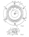
- the break-away coupling comprises two members having shaped body parts 10 and 11 of generally tubular form, which are formed at their adjacent ends with cooperating sealing faces 12 and 13. At their remote ends, the parts are formed with bored flanges 14, 15 for connection to the ends of lengths of a hoseline (not shown) for the delivery of hazardous fluid such as liquified petroleum gas (LPG).
- hazardous fluid such as liquified petroleum gas (LPG).
- each connector 18 has at one end a spatulate blade 19 formed with a bore for a fixing pin 20 and, at the other end, has a screwed length 21 to receive a shear nut 22, and a locating piece 23.
- a frangible length 24 of reduced section extends between the blade 19 and the locating piece 23.
- the blades 19 enter slots 25 in the flanges of the body part 11, with the pins 20 engaging recesses in the flange 17, and the screwed lengths 21 extending beyond the flange 16 of the body part 10; the locating pieces 23 are received by slots in the flange 16 and act to prevent the lengths 24 being subjected to torque when the nuts 22 are tightened.
- A, preferably odd, number greater than three connectors 18 may be provided.
- a series of three locating spigots 27 are bolted in bores in the flange 17 near the periphery of part 11, to enter locating sockets 28 in the coupling part 10 and resist relative rotation of the two coupling members which could rupture the connectors 18.
- the spigot heads 29 fit snugly in the sockets, and are formed with tapered leading ends to facilitate assembly of the coupling with the two parts 10 and 11 correctly orientated.
- valve members 30 and 31 which have stems 32 and 33 slidably mounted in spiders 34 and 35, respectively, and are urged towards the co-operating faces of the body parts by compression springs 36.
- stem 32 of valve member 30 (optionally) carries a piston member 37 which is accommodated in a chamber 38 in spider 34 to provide a one-way dashpot action, the dash-pot employing the fluid being delivered.
- the closing of valve member 30 is damped to prevent hydraulic hammering in the hoseline.
- valve member 31 A dash-pot device may also be provided for the valve member 31, or one or both valve-member stems may be simple sliding fits in the spiders (as is stem 33) in cases which rapid closure is required and fluid shock can be accommodated elsewhere in the line.
- the valve members 30 and 31 have valve heads 39 and 40 which include valve caps 41 and 42, each secured to the head by a bolt 43.
- Flat annular seals 44 are sandwiched one between each valve head and valve cap of the valve members, in positions to engage rim seats 45 inside the cooperating ends of the body parts 10 and 11. As can be seen from Figure 1, the valve heads and caps are accommodated in enlarged chambers 46.
- Central abutment limbs 47 and 48 extend integrally from the valve caps, and the abutting ends of the limbs may be of complementary concave and convex form (at 49) to centralise the valve members.
- the longer abutment limb 47 of cap 41 has a circumferential V-groove 50 to provide a weakened section allowing length 47A to be severed on separation of the coupling parts, thus avoiding the danger of projecting stems which would be liable to cause inadvertent opening of the valves.
- a shaped annular piston or ram 51 nests as a sliding fit in an annular channel 52 in the face 12 of coupling part 10, and a rib 53 extends to virtual engagement with the adjacent face 13.
- the ram is retained in the channel by means of circlips 54 which also act as stops, and at least one socket 55 is connected through bore(s) 56 to feed high pressure fluid to the base of the channel to actuate the ram in an emergency situation.
- the frangible lengths 24 of the connectors 18 will fracture before rupture of the hoseline itself.
- the valve members 30 will close promptly under the action of springs 36 possibly aided by the product pressure, so that the seals 44 engage the rim seats 45 and seal the ends of the hoseline with a minimum spillage of the fluid (such as LPG) being conveyed.
- connectors and the complementary form of flanges employed prevents the incorrect use of standard and probably higher- strength bolts; also, alternative areas of breakage are provided, in addition to the section lengths 24 which will fail in tension, by pins 20 dimensioned to fail in shear, and the blades 19 may also or alternatively be designed to fail in shear.
- the pins 21 are formed of a material such as nylon or a lead alloy which will lose strength at predetermined high temperatures.
- the shear nuts 22 are each formed with a reduced section 58 so that, when tightened, the nut head 59 will shear off at a predetermined torque whereby the three connectors will be loaded to a desired and uniform degree. Also, the removal of the heads will minimise the risk of unauthorised or accidental dismantling of the coupling as a special tool would be required to remove the remaining (leading) lengths of the shear nuts.
- the ram 51 is operated to separate the body parts 10 and 11.
- high-pressure fluid suitably nitrogen from a remote storage bottle (not shown) connected to the socket(s) 55, is fed to the channel 52 to drive the ram rib 53 against the face 13, and break the connectors 18.
- the fluid feed can be effected by operating an emergency button or automatically, preferably with manual override in the latter case.
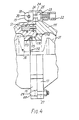
- the parts 110 and 111 have female and male cooperating faces 112 and 113.
- a sealing ring 115 is provided in an annular recess in cylindrical section 116 of the face 113.
- hydraulic pressure acts to maintain at least the seal 115 in fluid-tight contact with the cylindrical sections 116 and 117, this contact also being maintained during the initial period of a separating operation to minimise fluid loss.
- This arrangement is particularly useful for low- temperature applications where an 0-ring seal (114) between flat faces may fail due to deterioration of the seal material in the rectangular- section recesses.
- FIG. 4 construction also shows the frangible connectors 18 in a position which is reverse to that shown in Figures 1 to 3, but corresponding references donate corresponding parts.
- the spigots 27 and sockets 28 are as shown in the position of Figures 1 to 3.
- ram (51) may be modified.
- one or more individual cylindrical pistons, or an explosive device may be employed.
- the coupling is for incorporation in a hoseline, but one end part of the coupling may be connected to a fixed supply or delivery point.
- the coupling is incorporated in a metal or other more-or-less rigid pipeline which may be subjected to line- shock or surge pressures, the connectors being designed to fracture when the pressure exceeds a predetermined value.
Landscapes
- Engineering & Computer Science (AREA)
- General Engineering & Computer Science (AREA)
- Mechanical Engineering (AREA)
- Chemical & Material Sciences (AREA)
- Combustion & Propulsion (AREA)
- Ocean & Marine Engineering (AREA)
- Quick-Acting Or Multi-Walled Pipe Joints (AREA)
- Safety Valves (AREA)
Claims (10)
Priority Applications (1)
| Application Number | Priority Date | Filing Date | Title |
|---|---|---|---|
| AT84900080T ATE40920T1 (de) | 1982-11-30 | 1983-11-30 | Trennkupplung fuer schlauchleitungen. |
Applications Claiming Priority (2)
| Application Number | Priority Date | Filing Date | Title |
|---|---|---|---|
| GB8234036 | 1982-11-30 | ||
| GB8234036 | 1982-11-30 |
Publications (2)
| Publication Number | Publication Date |
|---|---|
| EP0159984A1 EP0159984A1 (de) | 1985-11-06 |
| EP0159984B1 true EP0159984B1 (de) | 1989-02-22 |
Family
ID=10534613
Family Applications (1)
| Application Number | Title | Priority Date | Filing Date |
|---|---|---|---|
| EP84900080A Expired EP0159984B1 (de) | 1982-11-30 | 1983-11-30 | Trennkupplung für schlauchleitungen |
Country Status (5)
| Country | Link |
|---|---|
| US (1) | US4921000A (de) |
| EP (1) | EP0159984B1 (de) |
| AU (1) | AU2344984A (de) |
| DE (1) | DE3379236D1 (de) |
| WO (1) | WO1984002171A1 (de) |
Cited By (2)
| Publication number | Priority date | Publication date | Assignee | Title |
|---|---|---|---|---|
| DE4202491C1 (en) * | 1991-11-28 | 1993-05-06 | Guenter 2050 Boernsen De Rathje | Tear-off coupling for liq. or gas pipelines - has flanges with breakable elements and valve discs spring-loaded to close off pipe ends |
| EP4086497A1 (de) * | 2021-05-06 | 2022-11-09 | Alpha Process Controls (International) Ltd. | Kopplung |
Families Citing this family (30)
| Publication number | Priority date | Publication date | Assignee | Title |
|---|---|---|---|---|
| EP0260965B2 (de) * | 1986-09-18 | 2002-01-16 | Pacific Biotech Inc. | Immunodiagnostische Vorrichtung |
| FR2638731B1 (fr) * | 1988-11-09 | 1991-02-08 | Fmc Europe | Procede pour assurer une deconnexion entre un bras de chargement de fluide et une citerne dont l'un est porte par un vehicule en cas de depart inopine du vehicule; bras de chargement de fluide mettant en oeuvre ce procede; deconnecteur de securite pour sa mise en oeuvre |
| US5141014A (en) * | 1991-05-28 | 1992-08-25 | M. Carder Industries, Inc. | Breakaway coupling |
| US5404909A (en) * | 1992-06-11 | 1995-04-11 | Parker-Hannifin Corporation | Coupling device |
| US5791366A (en) * | 1996-01-16 | 1998-08-11 | Preece Incorporated | Frangible quick disconnect coupling |
| US5758682A (en) * | 1996-06-05 | 1998-06-02 | Metal Goods Manufacturing Company | Safety shut off valve |
| US5887619A (en) * | 1996-12-10 | 1999-03-30 | Keary; John Robert | Dry disconnect coupling assembly |
| US7625354B2 (en) * | 1998-04-10 | 2009-12-01 | Milestone Scientific, Inc. | Handpiece for fluid administration apparatus |
| GB2342709B (en) * | 1998-10-16 | 2002-12-31 | Risbridger Ltd | Shear valve |
| CA2349262A1 (en) * | 2000-12-27 | 2002-06-27 | S&C Electric Company | Pressure relief arrangement for a housing |
| US6945477B2 (en) | 2002-09-04 | 2005-09-20 | Parker-Hannifin Corporation | Cryogenic coupling device |
| FR2858843B1 (fr) * | 2003-08-14 | 2007-05-11 | Ksb Sas | Dispositif de mise en communication de deux conduits a moyens de destruction |
| TWM310982U (en) * | 2006-12-13 | 2007-05-01 | Yi-Jr Bai | Security protection structure of high-pressure gas connector |
| EP2808293A1 (de) * | 2013-05-31 | 2014-12-03 | Shell Internationale Research Maatschappij B.V. | Ladeanordnung zum Fördern eines Druckgases und eine schwimmenden Gasverarbeitungseinheit |
| US9121536B2 (en) * | 2013-06-20 | 2015-09-01 | Zena Associates, Llc | High-pressure fluid conduit |
| US9625074B2 (en) * | 2013-06-20 | 2017-04-18 | Zena Associates, Llc | High-pressure fluid conduit |
| CN105658570B (zh) | 2013-10-18 | 2017-11-17 | 国际壳牌研究有限公司 | 用于输送加压气流的装载组件和使用在装载组件中的切换系统 |
| MX2016013326A (es) * | 2014-04-11 | 2017-01-18 | Emerson Process Man Regulator Technologies Inc | Ensamblaje de separacion de mangueras bidireccional. |
| WO2015168558A1 (en) | 2014-05-02 | 2015-11-05 | Goehler Dannie | Pressure release valve for oil recovery systems |
| US9845896B2 (en) | 2015-03-06 | 2017-12-19 | Opw Fueling Components Inc. | Shear valve |
| CN105221932B (zh) * | 2015-10-19 | 2017-12-26 | 武汉三江航天远方科技有限公司 | 低温流体装卸臂用紧急脱离装置 |
| US10221984B2 (en) | 2016-05-10 | 2019-03-05 | Zena Associates, Llc | High-pressure cryogenic fluid conduit |
| US20180258683A1 (en) * | 2016-05-27 | 2018-09-13 | John Wellman | Truck Hopper Gate Opener |
| KR101718332B1 (ko) * | 2016-06-03 | 2017-03-21 | 한국건설기술연구원 | 가스파이프 라인용 안티 서지 밸브 |
| SE540422C2 (en) | 2016-07-05 | 2018-09-11 | Mann Teknik Ab | Perc control and monitoring system |
| SE542140C2 (en) * | 2017-11-08 | 2020-03-03 | Mann Teknik Ab | Improved coupling with pressure relief |
| GB2580038B (en) * | 2018-12-19 | 2022-08-17 | Gall Thomson Environmental Ltd | Coupling |
| JP7430780B2 (ja) * | 2019-08-23 | 2024-02-13 | ホルマトロ・ベー・フェー | カップリングを選択的に結合又は分離する方法、及びそのためのカップリング |
| GB2588169A (en) * | 2019-10-11 | 2021-04-21 | Gall Thomson Environmental Ltd | Securing device |
| US11603943B2 (en) | 2021-02-03 | 2023-03-14 | Spectrum Associates, Inc. | Self-sealing breakaway valve |
Family Cites Families (20)
| Publication number | Priority date | Publication date | Assignee | Title |
|---|---|---|---|---|
| US1394072A (en) * | 1920-07-23 | 1921-10-18 | Charles C Egbert | Pressure-relief device |
| US2333423A (en) * | 1941-09-29 | 1943-11-02 | Thompson Prod Inc | Quick disconnect coupling |
| US2419642A (en) * | 1945-08-17 | 1947-04-29 | Guy J Henry | Pipe coupling |
| US2917077A (en) * | 1953-11-09 | 1959-12-15 | Phillips Petroleum Co | Excess flow check valve |
| US2798446A (en) * | 1954-02-02 | 1957-07-09 | Endrezze William Eugene | Concussion breaker |
| US2910080A (en) * | 1956-11-05 | 1959-10-27 | Tokheim Corp | Impact responsive valve |
| US3582017A (en) * | 1968-09-13 | 1971-06-01 | Ltv Aerospace Corp | Magnetic separation device |
| CH528038A (de) * | 1971-02-25 | 1972-09-15 | Bbc Brown Boveri & Cie | Sicherheitsventil mit membranartigem Zerreissglied |
| US3741521A (en) * | 1971-06-03 | 1973-06-26 | H Tatsuno | Pipe coupling with safety valve |
| US4064889A (en) * | 1976-02-17 | 1977-12-27 | Sun Oil Company Of Pennsylvania | Break-away safety valve |
| US4056117A (en) * | 1976-11-04 | 1977-11-01 | Procor Limited | Bottom outlet safety closure |
| DE2717135C3 (de) * | 1977-04-19 | 1985-07-18 | Wiese, Knut, 4600 Dortmund | Einrichtung zum Trennen einer Flüssigkeitsleitung mit großem Querschnitt |
| US4139222A (en) * | 1977-04-22 | 1979-02-13 | Santa Fe International Corp. | Quick connect/disconnect coupling assembly |
| US4127142A (en) * | 1977-05-11 | 1978-11-28 | James Allen Snider | Slow close hydrant check valve |
| EP0006278B1 (de) * | 1978-02-04 | 1983-05-18 | Gall Thomson Maritime Limited | Abreissrohrkupplung |
| GB2051993B (en) * | 1979-06-16 | 1983-04-27 | Gall Thomson Maritime Ltd | Breakaway coupling |
| GB2076917B (en) * | 1980-06-03 | 1984-06-13 | Alpha Process Control | Break-away coupling for incorporation in hoselines or pipelines |
| US4351351A (en) * | 1980-08-07 | 1982-09-28 | Exxon Research And Engineering Co. | Breakaway pipe coupling with automatically closed valves |
| US4392513A (en) * | 1981-02-09 | 1983-07-12 | Parrish Reuel C | Quick disconnect safety coupling |
| US4424988A (en) * | 1981-12-28 | 1984-01-10 | Consumers' Gas Company Limited | Frangible pipe coupling |
-
1983
- 1983-11-30 EP EP84900080A patent/EP0159984B1/de not_active Expired
- 1983-11-30 AU AU23449/84A patent/AU2344984A/en not_active Abandoned
- 1983-11-30 WO PCT/GB1983/000312 patent/WO1984002171A1/en active IP Right Grant
- 1983-11-30 US US06/637,227 patent/US4921000A/en not_active Expired - Lifetime
- 1983-11-30 DE DE8484900080T patent/DE3379236D1/de not_active Expired
Cited By (2)
| Publication number | Priority date | Publication date | Assignee | Title |
|---|---|---|---|---|
| DE4202491C1 (en) * | 1991-11-28 | 1993-05-06 | Guenter 2050 Boernsen De Rathje | Tear-off coupling for liq. or gas pipelines - has flanges with breakable elements and valve discs spring-loaded to close off pipe ends |
| EP4086497A1 (de) * | 2021-05-06 | 2022-11-09 | Alpha Process Controls (International) Ltd. | Kopplung |
Also Published As
| Publication number | Publication date |
|---|---|
| WO1984002171A1 (en) | 1984-06-07 |
| EP0159984A1 (de) | 1985-11-06 |
| AU2344984A (en) | 1984-06-18 |
| US4921000A (en) | 1990-05-01 |
| DE3379236D1 (en) | 1989-03-30 |
Similar Documents
| Publication | Publication Date | Title |
|---|---|---|
| EP0159984B1 (de) | Trennkupplung für schlauchleitungen | |
| US4614201A (en) | Break-away coupling for hoselines | |
| US4392513A (en) | Quick disconnect safety coupling | |
| EP0236256A2 (de) | Abreisskupplung | |
| US3719194A (en) | Breakaway coupling | |
| US4348039A (en) | Release coupling | |
| US4090524A (en) | Frangible valved fitting | |
| US4449545A (en) | Breakaway safety valve | |
| US5707152A (en) | Method for using reusable pipe union and pipe cap assembly for wide thermal cycling | |
| EP0650005B1 (de) | Trennkupplung für konzentrische Schläuche | |
| AU604973B2 (en) | Integral metal seal for hydraulic coupling | |
| US4872471A (en) | Separable and breakaway valve interconnecting a fluid line | |
| US5678607A (en) | Reusable pipe union and pipe cap assembly for wide thermal cycling | |
| GB2076917A (en) | Break-away coupling for incorporation in hoselines or pipelines | |
| US5791366A (en) | Frangible quick disconnect coupling | |
| US4483359A (en) | Pull away spill guard | |
| WO2018065761A1 (en) | Pipeline coupling | |
| US5454602A (en) | Fuel hose breakaway unit | |
| US4501287A (en) | Breakaway coupling | |
| KR101949323B1 (ko) | 브레이크어웨이 커플링용 케이싱 및 브레이킹 볼트 | |
| US5054509A (en) | Breakaway coupling, conduit system utilizing the coupling and methods of making the same | |
| US4688827A (en) | Pipeline safety joint | |
| EP1859191B1 (de) | Druckaktivierte kopplung einer lösesperre | |
| CA1208253A (en) | Break-away coupling for hoselines | |
| US4884591A (en) | Reconnectable frangible ball valve coupling |
Legal Events
| Date | Code | Title | Description |
|---|---|---|---|
| PUAI | Public reference made under article 153(3) epc to a published international application that has entered the european phase |
Free format text: ORIGINAL CODE: 0009012 |
|
| 17P | Request for examination filed |
Effective date: 19841231 |
|
| AK | Designated contracting states |
Designated state(s): AT BE CH DE FR GB LI LU NL SE |
|
| 17Q | First examination report despatched |
Effective date: 19870727 |
|
| GRAA | (expected) grant |
Free format text: ORIGINAL CODE: 0009210 |
|
| AK | Designated contracting states |
Kind code of ref document: B1 Designated state(s): AT BE CH DE FR GB LI LU NL SE |
|
| PG25 | Lapsed in a contracting state [announced via postgrant information from national office to epo] |
Ref country code: SE Effective date: 19890222 Ref country code: NL Effective date: 19890222 Ref country code: LI Effective date: 19890222 Ref country code: CH Effective date: 19890222 Ref country code: BE Effective date: 19890222 Ref country code: AT Effective date: 19890222 |
|
| REF | Corresponds to: |
Ref document number: 40920 Country of ref document: AT Date of ref document: 19890315 Kind code of ref document: T |
|
| REF | Corresponds to: |
Ref document number: 3379236 Country of ref document: DE Date of ref document: 19890330 |
|
| REG | Reference to a national code |
Ref country code: CH Ref legal event code: PL |
|
| NLV1 | Nl: lapsed or annulled due to failure to fulfill the requirements of art. 29p and 29m of the patents act | ||
| ET | Fr: translation filed | ||
| PG25 | Lapsed in a contracting state [announced via postgrant information from national office to epo] |
Ref country code: LU Free format text: LAPSE BECAUSE OF NON-PAYMENT OF DUE FEES Effective date: 19891130 |
|
| PLBE | No opposition filed within time limit |
Free format text: ORIGINAL CODE: 0009261 |
|
| STAA | Information on the status of an ep patent application or granted ep patent |
Free format text: STATUS: NO OPPOSITION FILED WITHIN TIME LIMIT |
|
| 26N | No opposition filed | ||
| PGFP | Annual fee paid to national office [announced via postgrant information from national office to epo] |
Ref country code: GB Payment date: 19901127 Year of fee payment: 8 |
|
| PGFP | Annual fee paid to national office [announced via postgrant information from national office to epo] |
Ref country code: FR Payment date: 19901129 Year of fee payment: 8 Ref country code: DE Payment date: 19901129 Year of fee payment: 8 |
|
| PG25 | Lapsed in a contracting state [announced via postgrant information from national office to epo] |
Ref country code: GB Effective date: 19911130 |
|
| GBPC | Gb: european patent ceased through non-payment of renewal fee | ||
| PG25 | Lapsed in a contracting state [announced via postgrant information from national office to epo] |
Ref country code: FR Effective date: 19920731 |
|
| PG25 | Lapsed in a contracting state [announced via postgrant information from national office to epo] |
Ref country code: DE Effective date: 19920801 |
|
| REG | Reference to a national code |
Ref country code: FR Ref legal event code: ST |