EP0159799A2 - Robinet à tournant sphérique - Google Patents
Robinet à tournant sphérique Download PDFInfo
- Publication number
- EP0159799A2 EP0159799A2 EP85301822A EP85301822A EP0159799A2 EP 0159799 A2 EP0159799 A2 EP 0159799A2 EP 85301822 A EP85301822 A EP 85301822A EP 85301822 A EP85301822 A EP 85301822A EP 0159799 A2 EP0159799 A2 EP 0159799A2
- Authority
- EP
- European Patent Office
- Prior art keywords
- closure member
- valve
- stem
- operating means
- housing
- Prior art date
- Legal status (The legal status is an assumption and is not a legal conclusion. Google has not performed a legal analysis and makes no representation as to the accuracy of the status listed.)
- Granted
Links
Images

Classifications
-
- F—MECHANICAL ENGINEERING; LIGHTING; HEATING; WEAPONS; BLASTING
- F16—ENGINEERING ELEMENTS AND UNITS; GENERAL MEASURES FOR PRODUCING AND MAINTAINING EFFECTIVE FUNCTIONING OF MACHINES OR INSTALLATIONS; THERMAL INSULATION IN GENERAL
- F16K—VALVES; TAPS; COCKS; ACTUATING-FLOATS; DEVICES FOR VENTING OR AERATING
- F16K5/00—Plug valves; Taps or cocks comprising only cut-off apparatus having at least one of the sealing faces shaped as a more or less complete surface of a solid of revolution, the opening and closing movement being predominantly rotary
- F16K5/08—Details
- F16K5/14—Special arrangements for separating the sealing faces or for pressing them together
- F16K5/20—Special arrangements for separating the sealing faces or for pressing them together for plugs with spherical surfaces
- F16K5/204—Special arrangements for separating the sealing faces or for pressing them together for plugs with spherical surfaces with the plugs or parts of the plugs mechanically pressing the seals against the housing
-
- F—MECHANICAL ENGINEERING; LIGHTING; HEATING; WEAPONS; BLASTING
- F16—ENGINEERING ELEMENTS AND UNITS; GENERAL MEASURES FOR PRODUCING AND MAINTAINING EFFECTIVE FUNCTIONING OF MACHINES OR INSTALLATIONS; THERMAL INSULATION IN GENERAL
- F16K—VALVES; TAPS; COCKS; ACTUATING-FLOATS; DEVICES FOR VENTING OR AERATING
- F16K1/00—Lift valves or globe valves, i.e. cut-off apparatus with closure members having at least a component of their opening and closing motion perpendicular to the closing faces
- F16K1/24—Lift valves or globe valves, i.e. cut-off apparatus with closure members having at least a component of their opening and closing motion perpendicular to the closing faces with valve members that, on opening of the valve, are initially lifted from the seat and next are turned around an axis parallel to the seat
-
- F—MECHANICAL ENGINEERING; LIGHTING; HEATING; WEAPONS; BLASTING
- F16—ENGINEERING ELEMENTS AND UNITS; GENERAL MEASURES FOR PRODUCING AND MAINTAINING EFFECTIVE FUNCTIONING OF MACHINES OR INSTALLATIONS; THERMAL INSULATION IN GENERAL
- F16K—VALVES; TAPS; COCKS; ACTUATING-FLOATS; DEVICES FOR VENTING OR AERATING
- F16K5/00—Plug valves; Taps or cocks comprising only cut-off apparatus having at least one of the sealing faces shaped as a more or less complete surface of a solid of revolution, the opening and closing movement being predominantly rotary
- F16K5/06—Plug valves; Taps or cocks comprising only cut-off apparatus having at least one of the sealing faces shaped as a more or less complete surface of a solid of revolution, the opening and closing movement being predominantly rotary with plugs having spherical surfaces; Packings therefor
- F16K5/0647—Spindles or actuating means
Definitions
- This invention relates in general to the construction of valves and in particular to a new housing containing a closure member of the ball valve type wherein the closure member is carried on an eccentric so as to permit angular movement of the closure member about an axis and in addition, radial movement with respect to that axis.
- the present invention relates to the construction of a ball or globe valve, particularly for use in shutting off pipelines and the like.
- Ball valves are known generally. They have several advantages including being relatively economical to manufacture and requiring relatively little maintenance.
- One of the disadvantages of ball valves is that the valves are often used on high pressure lines such as gas and oil transmission lines and thus require a significant amount of force between the ball and the seat against which the ball seals. Angular movement of the ball with respect to its seat causes failure of the seal whether the seal is carried by the ball or the seat. When the seal fails the pipeline must be shut down and the valve entirely disassembled to replace the seat.
- a valve of the ball or globe type in which the housing comprises an inlet, an outlet and an inspection or maintenance port.
- the closure member is contained within the housing and comprises a sealing surface co-operating with a seat rounding the inlet for shutting off flow through the valve.
- Operating means are provided to cause movement of the closure element in two different directions.
- To open the valve the closure member is moved firstly in a direction away from the seat carried by the inlet.
- the valve may then be rotated through a convenient angle about an axis to a second position in which the passage through the closure member is in fluid communication with the inlet and the outlet. When in the second position the seating surface of the closure member is adjacent to and aligned with the inspection port.
- the closure member may then be moved in a direction radial to the axis of angular movement towards the inspection port to seal against the inspection port.
- the valve When in the latter position the valve is open permitting flow through the line while at the same time the main seal is available through the access port for inspection and repair.
- the operating mechanism for the closure member comprises a main stem to give angular displacement of the closure member about the axis and an auxiliary stem to give the radial displacement.
- the auxiliary stem is contained within and is concentric with the main stem.
- the auxiliary stem comprises an eccentric portion journalled in the closure member.
- the main stem has a yoke-shaped end which co-operates with a boss on the closure element permitting relative sliding between the yoke and boss during radial movement.
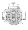
- a ball valve indicated generally at 10 comprising a main housing 12, and upper housing 14 and a closure member 16.
- the main housing 12 comprises an inlet flange 18 and an outlet flange 20 in order that the ball valve may be connected to a pipeline in the standard fashion.
- the inlet flange and outlet flange together with the main housing respectively define inlets and outlets having passages for fluid flow.
- the main housing 12 comprises a valve seat 22 illustrated in Figure 1 against which the closure member seals to prevent flow along the fluid passage.
- the closure member 16 comprises a surface 24 for co-operating with the valve seat 22.
- the surface 24 has inset therein an annular neoprene main seal 26.
- Main seal 26 is maintained within the surface 24 of the closure member 16 by a main seal retainer 28 which is affixed to closure member 16 by means of countersunk bolts 29.
- the interaction between valve seat 22 and neoprene main seal 26 provides the main sealing interface between the closure member 16 and the main housing 12. In Figure 1 the valve is shown in the closed position.
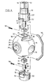
- the closure member 16 is illustrated in exploded perspective view in Figure 4.
- the closure member 16 comprises a central passage 30 extending therethrough for communication of fluid flow between the inlet and outlet portions of the housing.
- the passage 30 is of approximately the same internal diameter as the inlet and outlet passages of main housing 12.
- the closure member 16 is substantially spherical shaped in the region of the surface 24. The remainder of the surface may be relieved from the spherical outline to provide a lighter more compact and more inexpensive closure member.
- the upper and lower portions of the closure member 16 as illustrated in Figure 4 comprise boss structures 32 and 34 respectively. As illustrated in Figure 4 upper boss 32 is defined by a pair of flat surfaces 36 and a pair of flat surfaces at right angles thereto 38. Lower boss 34 is similarly defined by a pair of flat surfaces on either side and a second pair of flat surfaces at right angles thereto.
- Upper boss 32 comprises a rectangular chamber 40 for receiving upper journal bearing 42.
- Upper journal bearing 42 is closely received by chamber 40 so as to preclude any relative movement therebetween.
- Lower boss 34 also comprises a chamber, not visible, which chamber, similarly, closely receives lower journal bearing 44.
- Angular motion of the closure member 16 about an axis is provided by movement of main stem 50.
- the end of main stem 50 adjacent closure member 16 comprises a cylindrical yoke 52 having a flat lower surface 51 and flat internal surfaces 53.
- the yoke 52 of main stem 50 is closely received by boss 32 so that the lower surface 51 of the main stem rests against surfaces 38 while the internal surfaces 53 of the yoke are closely adjacent surfaces 36.
- rotation of the main stem about its axis 54 will rotate the closure member 16 about that same axis.
- Lower main stem 70 is similarly provided with a yoke-shaped end 72 which accommodates lower boss 34. As illustrated in Figure 1 lower main stem 70 is rotatably received in main housing 12 to support and locate the closure member 16. Upper main stem 50 is received in and located by upper housing 14 thus providing support for the closure member 16. The upper main stem is retained in upper housing 14 by means of threaded cap 80 which is threadedly received in upper housing 14.
- Upper housing 14 is retained in main housing 12 by means of bolts 82.
- An O-ring seal 84 on upper housing 14 serves to seal upper housing 14 to main housing 12.
- a pair of seals or gaskets 86 and 88 are compressed by the end cap 80 and serve to seal end cap 80 to upper housing 14.
- main stem 50 comprises a hollow bore 62 the upper part of which is co-axial with axis 54.
- the mid portion 64 of bore 62 comprises a bore of larger diameter.
- the lowermost portion 66 of bore 62 comprises an eccentric bore having an axis offset from and parallel to axis 54.
- An upper auxiliary stem 90 is provided in order to achieve radial motion of the closure member 16 with respect to axis 54.
- the upper auxiliary stem 90 comprises a cylindrical shaft which is receivable in bore 62.
- the uppermost portion 92 is concentric with axis 54.
- the lowermost portion 94 of the upper auxiliary stem 90 comprises a cylindrical shaft with the axis 96 of this lower portion parallel to but spaced from the axis 54 thereby providing an eccentric.
- the lowermost portion 94 of the upper auxiliary stem 90 is closely received within a bore in upper journal bearing 42.
- the lower main stem 70 also comprises a central bore 74 which bore is co-axial with axis 54.
- Lower auxiliary stem 100 comprises a first cylindrical portion 102 which is received within bore 74 of lower main stem 70.
- the lower auxiliary stem 100 also comprises an upper cylindrical portion 104 which is co-axial with axis 96.
- the upper cylindrical portion 104 of lower auxiliary stem 100 is received within the bore of the lower journal bearing 44.
- Upper auxiliary stem 90 is connected to lower auxiliary stem 100 by means of connecting bar 110.
- Connecting bar 110 is affixed to upper auxiliary stem 90 and lower auxiliary stem 100 by means of bolts 112. These bolts have not been illustrated in Figure 1 in order to provide further clarity of the bearing details in that sectional view.
- FIG. 1 the valve is shown in the closed position.
- a suitable valve wrench is applied to upper auxiliary stem 90 to turn upper auxiliary stem 90 about axis 54 approximately 1/2 turn. Movement of upper auxiliary stem 90 will cause similar movement of lower auxiliary stem 100 as these stems are interconnected by the connecting bar 110.
- Upper main stem 50 and lower main stem 74 each comprise a horizontal slot 111 to accommodate the movement of connecting bar 110.
- FIG. 1 the closure member is shown in the closed position but connecting bar is shown in the "half way” position so as to show the connecting bar more clearly.
- Each of upper auxiliary stem 90 and lower auxiliary stem 100 will achieve angular movement about axis 54 as upper auxiliary stem 90 is received within the main stem 50 and lower auxiliary stem 100 is received within lower main stem 70.
- the lowermost portion 94 of upper auxiliary stem will thus move eccentrically about axis 54.
- the uppermost portion 104 of lower auxiliary stem 100 will similarly move eccentrically about axis 54.
- the numeral 96A is used to designate the axis 96 of portions 94 and 104 when in the closed position while the numeral 96B is used to denote the position of the axis 96 following movement of auxiliary stems 90 and 100.
- the movement of portions 94 and 104 from position 96A to 96B causes movement of the journal bearings 42 and 44 to the right in Figure 1.
- the closure member 16 must also move to the right a similar distance.
- the closure member 16 is free to move to the right under such motion by sliding the bosses 32 and 34 to the right within yoke 52 of main stem 50 and yoke 72 of lower main stem 70. Accordingly the closure member 16 will be drawn to the right in Figure 1 so that the annular seal 26 is withdrawn from the valve seat 22. This is achieved by approximately 180 degrees rotation of the upper auxiliary stem 90.
- the second stage in the opening of the valve is the rotation of the main stem 50.
- Rotation of the main stem 50 through an angle of approximately 90 degrees will cause rotation of the closure member 16 about axis 54 to bring the passage 30 into registration with the inlet and outlet passages of the housing.
- the valve is in the opened position with fluid flowing through the housing and the closure member 12 not sealed against either the inlet or outlet passages.
- fluid pressure will fill the housing but there will be no substantial flow around the exterior surface of the closure member 16. Leakage of fluid along the bore 66 of the main stem is prevented by 0-ring seals 120 and 122 illustrated in Figure 1.
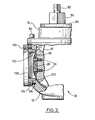
- Figure 3 illustrates the valve with the closure member 16 in the position to be inspected.
- the upper auxiliary stem 90 may be moved back through 180 degrees. Such movement will cause radial movement of the closure member 16 with respect to axis 54 toward the maintenance port 130.
- Figure 2 illustrates that the maintenance port 130 is most advantageously at an angle of 90 degrees to the inlet and outlet passages.
- Maintenance seal 132 is an annular member set into the surface of a maintenance seal retainer 134.
- Maintenance seal retainer 134 is affixed to main housing 12 by means of countersunk bolts 136.
- the maintenance port is closed by means of a maintenance cover plate 138 which is affixed to the maintenance seal retainer by means of countersunk bolts 140.
- the maintenance port 130 is of larger diameter than the main seal 26.
- the closure member 16 When inspection or replacement of main seal 26 is required the closure member 16 is moved to the position illustrated in Figure 3. Maintenance cover plate 138 is removed by removing countersunk bolts 140. The main seal 26 may then be inspected by viewing through maintenance port 130. If replacement of the main seal is required the bolts 29 may be removed in order that the main seal retainer 28 can be taken out. Upon removal of the bolts 29 and the main seal retainer 28 the main seal 26 may be replaced.
- the device of this invention provides a mechanism by means of which the main seal may be inspected and replaced without the necessity of shutting down the pipeline.
- the next step in the assembly process is to subassemble the closure member and the upper and lower auxiliary -tem. Firstly, the lower journal bearing 44 and the upper journal bearing 42 are placed in the bosses 34 and 32 respectively. Then lower auxiliary stem 100 is seated within the lower journal bearing 44. This is followed by insertion of upper auxiliary stem 90 into upper journal bearing 42. Connecting bar 110 is then bolted to the upper auxiliary stem 90 and the lower auxiliary stem 100 using bolts 112. At this time, the subassembly may then be inserted in the main housing 12 with the lower auxiliary stem 100 being seated in the lower main stem 70 and the boss 34 being received within the yoke 72.
- the upper main stem 50 may be passed downwardly over the upper auxiliary stem 90 with the yoke 52 of the upper main stem 50 straddling the boss 32. Thereafter the housing may be closed by bolting the upper housing 14 in place and then screwing on end cap 80.
- the maintenance port may be disassembled and assembled as indicated above at any time as convenient.
Landscapes
- Engineering & Computer Science (AREA)
- General Engineering & Computer Science (AREA)
- Mechanical Engineering (AREA)
- Taps Or Cocks (AREA)
- External Artificial Organs (AREA)
- Fuel-Injection Apparatus (AREA)
- Temperature-Responsive Valves (AREA)
- Details Of Valves (AREA)
Priority Applications (1)
| Application Number | Priority Date | Filing Date | Title |
|---|---|---|---|
| AT85301822T ATE58580T1 (de) | 1984-03-15 | 1985-03-15 | Kugelhahn. |
Applications Claiming Priority (2)
| Application Number | Priority Date | Filing Date | Title |
|---|---|---|---|
| US58992084A | 1984-03-15 | 1984-03-15 | |
| US589920 | 1984-03-15 |
Publications (3)
| Publication Number | Publication Date |
|---|---|
| EP0159799A2 true EP0159799A2 (fr) | 1985-10-30 |
| EP0159799A3 EP0159799A3 (en) | 1986-08-06 |
| EP0159799B1 EP0159799B1 (fr) | 1990-11-22 |
Family
ID=24360110
Family Applications (1)
| Application Number | Title | Priority Date | Filing Date |
|---|---|---|---|
| EP85301822A Expired - Lifetime EP0159799B1 (fr) | 1984-03-15 | 1985-03-15 | Robinet à tournant sphérique |
Country Status (4)
| Country | Link |
|---|---|
| EP (1) | EP0159799B1 (fr) |
| AT (1) | ATE58580T1 (fr) |
| CA (1) | CA1228584A (fr) |
| DE (1) | DE3580609D1 (fr) |
Cited By (7)
| Publication number | Priority date | Publication date | Assignee | Title |
|---|---|---|---|---|
| GB2203818A (en) * | 1987-03-03 | 1988-10-26 | R A J Thomson Pipework & Valve | Improvements in or relating to valves |
| EP0786611A1 (fr) * | 1996-01-25 | 1997-07-30 | Aktiebolaget Somas Ventiler | Soupape à sphère segmentée et arrangement d'une soupape à sphère segmentée |
| EP2754932A4 (fr) * | 2011-09-05 | 2015-08-05 | Shanghai Hongyan Returnable Transit Packagings Co Ltd | Ensemble noyau de vanne et vanne utilisant l'ensemble noyau de vanne |
| CN104864113A (zh) * | 2015-04-18 | 2015-08-26 | 张新丰 | 一种带导轨硬密封球阀 |
| IT201600083938A1 (it) * | 2016-08-09 | 2018-02-09 | Enolgas Bonomi S P A | Corpo valvola e valvola a sfera con riscontro di fine corsa dell’otturatore |
| WO2018067096A3 (fr) * | 2016-08-12 | 2018-07-12 | Godes Mustafa | Robinet à tournant sphérique sans friction |
| CN114729700A (zh) * | 2019-11-21 | 2022-07-08 | Itt制造企业有限责任公司 | 双运动关闭阀 |
Citations (7)
| Publication number | Priority date | Publication date | Assignee | Title |
|---|---|---|---|---|
| DE679949C (de) * | 1936-03-13 | 1939-08-18 | Schaeffer & Budenberg G M B H | Drehventil |
| US2233074A (en) * | 1939-02-21 | 1941-02-25 | William C Biddle | Rotary gate and orifice valve |
| US2577725A (en) * | 1944-09-29 | 1951-12-11 | Robert W Drake | Eccentric ball valve for highpressure lines |
| FR1104872A (fr) * | 1954-05-17 | 1955-11-24 | Robinet-vanne à fermeture rapide | |
| FR2383369A1 (fr) * | 1977-03-10 | 1978-10-06 | Nuovo Pignone Spa | Vanne spherique |
| US4273152A (en) * | 1979-02-09 | 1981-06-16 | Freeman Murray E | Control valve assembly with onstream seal removal feature |
| EP0107868A1 (fr) * | 1982-10-27 | 1984-05-09 | Giorgio Bormioli | Robinet à obturateur sphérique avec rotation et translation de l'obturateur pour des fluides à très hautes ou très basses températures |
-
1984
- 1984-03-23 CA CA000450414A patent/CA1228584A/fr not_active Expired
-
1985
- 1985-03-15 AT AT85301822T patent/ATE58580T1/de not_active IP Right Cessation
- 1985-03-15 EP EP85301822A patent/EP0159799B1/fr not_active Expired - Lifetime
- 1985-03-15 DE DE8585301822T patent/DE3580609D1/de not_active Expired - Lifetime
Patent Citations (7)
| Publication number | Priority date | Publication date | Assignee | Title |
|---|---|---|---|---|
| DE679949C (de) * | 1936-03-13 | 1939-08-18 | Schaeffer & Budenberg G M B H | Drehventil |
| US2233074A (en) * | 1939-02-21 | 1941-02-25 | William C Biddle | Rotary gate and orifice valve |
| US2577725A (en) * | 1944-09-29 | 1951-12-11 | Robert W Drake | Eccentric ball valve for highpressure lines |
| FR1104872A (fr) * | 1954-05-17 | 1955-11-24 | Robinet-vanne à fermeture rapide | |
| FR2383369A1 (fr) * | 1977-03-10 | 1978-10-06 | Nuovo Pignone Spa | Vanne spherique |
| US4273152A (en) * | 1979-02-09 | 1981-06-16 | Freeman Murray E | Control valve assembly with onstream seal removal feature |
| EP0107868A1 (fr) * | 1982-10-27 | 1984-05-09 | Giorgio Bormioli | Robinet à obturateur sphérique avec rotation et translation de l'obturateur pour des fluides à très hautes ou très basses températures |
Cited By (12)
| Publication number | Priority date | Publication date | Assignee | Title |
|---|---|---|---|---|
| GB2203818A (en) * | 1987-03-03 | 1988-10-26 | R A J Thomson Pipework & Valve | Improvements in or relating to valves |
| EP0786611A1 (fr) * | 1996-01-25 | 1997-07-30 | Aktiebolaget Somas Ventiler | Soupape à sphère segmentée et arrangement d'une soupape à sphère segmentée |
| US5820103A (en) * | 1996-01-25 | 1998-10-13 | Aktiebolaget Somas Ventiler | Ball segment valve and ball segment valve arrangement |
| AU710573B2 (en) * | 1996-01-25 | 1999-09-23 | Aktiebolaget Somas Ventiler | Ball segment valve and ball segment valve arrangement |
| KR100468304B1 (ko) * | 1996-01-25 | 2005-04-14 | 악티에볼라겟 조마스 벤틸러 | 볼세그먼트밸브 |
| EP2754932A4 (fr) * | 2011-09-05 | 2015-08-05 | Shanghai Hongyan Returnable Transit Packagings Co Ltd | Ensemble noyau de vanne et vanne utilisant l'ensemble noyau de vanne |
| CN104864113A (zh) * | 2015-04-18 | 2015-08-26 | 张新丰 | 一种带导轨硬密封球阀 |
| IT201600083938A1 (it) * | 2016-08-09 | 2018-02-09 | Enolgas Bonomi S P A | Corpo valvola e valvola a sfera con riscontro di fine corsa dell’otturatore |
| EP3282154A1 (fr) * | 2016-08-09 | 2018-02-14 | Enolgas Bonomi S.p.A. | Robinet d'arrêt |
| WO2018067096A3 (fr) * | 2016-08-12 | 2018-07-12 | Godes Mustafa | Robinet à tournant sphérique sans friction |
| CN114729700A (zh) * | 2019-11-21 | 2022-07-08 | Itt制造企业有限责任公司 | 双运动关闭阀 |
| CN114729700B (zh) * | 2019-11-21 | 2024-03-01 | Itt制造企业有限责任公司 | 双运动关闭阀 |
Also Published As
| Publication number | Publication date |
|---|---|
| DE3580609D1 (de) | 1991-01-03 |
| ATE58580T1 (de) | 1990-12-15 |
| EP0159799B1 (fr) | 1990-11-22 |
| EP0159799A3 (en) | 1986-08-06 |
| CA1228584A (fr) | 1987-10-27 |
Similar Documents
| Publication | Publication Date | Title |
|---|---|---|
| US4634098A (en) | Ball Valve | |
| US20010045231A1 (en) | Ball valve with replaceable cartridge insert | |
| US2821998A (en) | Rotary selector valve | |
| US3037738A (en) | Rotor valve | |
| US4554948A (en) | Straight-way valve | |
| US3576309A (en) | Top entry ball valve | |
| US4953587A (en) | Ball valves for pipelines | |
| US7484523B2 (en) | Rotatable wedge cartridge valve mechanism and method for assembly and disassembly | |
| US3277919A (en) | Rotatable valve structure | |
| EP0159799A2 (fr) | Robinet à tournant sphérique | |
| US3838844A (en) | Top entry valve with aligned through passage | |
| US2895710A (en) | Ball valve | |
| JP2007139010A (ja) | ボールバルブ | |
| US8365755B2 (en) | Ball valve isolator | |
| US4577830A (en) | High pressure ball valve with an interference fit closure seal | |
| US6286810B1 (en) | Valve with cartridge | |
| US3531075A (en) | Butterfly valve | |
| US4342330A (en) | Ball type valve having improved redundant sealing system | |
| CN113266683A (zh) | 具有不受阻挡的流动路径且具有增大的流量系数的阀 | |
| NO166459B (no) | Spjeldventil av inspiserbar type. | |
| RU2137000C1 (ru) | Усовершенствованный водопроводный кран с шаровым клапаном | |
| EP1000282A1 (fr) | Robinet a bille avec elements tete et siege amovibles | |
| KR200334648Y1 (ko) | 세그먼트 플러그형 이중편심 메탈시트 볼밸브 | |
| US4433827A (en) | High pressure shut-off valve | |
| US7104521B2 (en) | Dual chamber orifice fitting valve |
Legal Events
| Date | Code | Title | Description |
|---|---|---|---|
| PUAI | Public reference made under article 153(3) epc to a published international application that has entered the european phase |
Free format text: ORIGINAL CODE: 0009012 |
|
| AK | Designated contracting states |
Designated state(s): AT BE CH DE FR GB IT LI LU NL SE |
|
| PUAL | Search report despatched |
Free format text: ORIGINAL CODE: 0009013 |
|
| AK | Designated contracting states |
Kind code of ref document: A3 Designated state(s): AT BE CH DE FR GB IT LI LU NL SE |
|
| 17P | Request for examination filed |
Effective date: 19870205 |
|
| 17Q | First examination report despatched |
Effective date: 19880406 |
|
| GRAA | (expected) grant |
Free format text: ORIGINAL CODE: 0009210 |
|
| AK | Designated contracting states |
Kind code of ref document: B1 Designated state(s): AT BE CH DE FR GB IT LI LU NL SE |
|
| PG25 | Lapsed in a contracting state [announced via postgrant information from national office to epo] |
Ref country code: LI Effective date: 19901122 Ref country code: CH Effective date: 19901122 |
|
| REF | Corresponds to: |
Ref document number: 58580 Country of ref document: AT Date of ref document: 19901215 Kind code of ref document: T |
|
| REF | Corresponds to: |
Ref document number: 3580609 Country of ref document: DE Date of ref document: 19910103 |
|
| ITF | It: translation for a ep patent filed |
Owner name: SOCIETA' ITALIANA BREVETTI S.P.A. |
|
| REG | Reference to a national code |
Ref country code: CH Ref legal event code: PL |
|
| ET | Fr: translation filed | ||
| ITTA | It: last paid annual fee | ||
| PG25 | Lapsed in a contracting state [announced via postgrant information from national office to epo] |
Ref country code: LU Free format text: LAPSE BECAUSE OF NON-PAYMENT OF DUE FEES Effective date: 19910331 |
|
| PLBE | No opposition filed within time limit |
Free format text: ORIGINAL CODE: 0009261 |
|
| STAA | Information on the status of an ep patent application or granted ep patent |
Free format text: STATUS: NO OPPOSITION FILED WITHIN TIME LIMIT |
|
| 26N | No opposition filed | ||
| PGFP | Annual fee paid to national office [announced via postgrant information from national office to epo] |
Ref country code: SE Payment date: 19920323 Year of fee payment: 8 |
|
| PGFP | Annual fee paid to national office [announced via postgrant information from national office to epo] |
Ref country code: BE Payment date: 19920324 Year of fee payment: 8 |
|
| PGFP | Annual fee paid to national office [announced via postgrant information from national office to epo] |
Ref country code: FR Payment date: 19920326 Year of fee payment: 8 |
|
| PGFP | Annual fee paid to national office [announced via postgrant information from national office to epo] |
Ref country code: NL Payment date: 19920331 Year of fee payment: 8 Ref country code: AT Payment date: 19920331 Year of fee payment: 8 |
|
| PGFP | Annual fee paid to national office [announced via postgrant information from national office to epo] |
Ref country code: DE Payment date: 19920430 Year of fee payment: 8 |
|
| PG25 | Lapsed in a contracting state [announced via postgrant information from national office to epo] |
Ref country code: AT Effective date: 19930315 |
|
| PGFP | Annual fee paid to national office [announced via postgrant information from national office to epo] |
Ref country code: GB Payment date: 19930315 Year of fee payment: 9 |
|
| PG25 | Lapsed in a contracting state [announced via postgrant information from national office to epo] |
Ref country code: SE Effective date: 19930316 |
|
| PG25 | Lapsed in a contracting state [announced via postgrant information from national office to epo] |
Ref country code: BE Effective date: 19930331 |
|
| BERE | Be: lapsed |
Owner name: VARDEN ARNOLD Effective date: 19930331 |
|
| PG25 | Lapsed in a contracting state [announced via postgrant information from national office to epo] |
Ref country code: NL Effective date: 19931001 |
|
| NLV4 | Nl: lapsed or anulled due to non-payment of the annual fee | ||
| PG25 | Lapsed in a contracting state [announced via postgrant information from national office to epo] |
Ref country code: FR Effective date: 19931130 |
|
| PG25 | Lapsed in a contracting state [announced via postgrant information from national office to epo] |
Ref country code: DE Effective date: 19931201 |
|
| REG | Reference to a national code |
Ref country code: FR Ref legal event code: ST |
|
| PG25 | Lapsed in a contracting state [announced via postgrant information from national office to epo] |
Ref country code: GB Effective date: 19940315 |
|
| GBPC | Gb: european patent ceased through non-payment of renewal fee |
Effective date: 19940315 |
|
| EUG | Se: european patent has lapsed |
Ref document number: 85301822.4 Effective date: 19931008 |