EP0159664B1 - Gasisoliertes elektrisches Gerät und dazugehöriges Zusammensetzungsverfahren - Google Patents
Gasisoliertes elektrisches Gerät und dazugehöriges Zusammensetzungsverfahren Download PDFInfo
- Publication number
- EP0159664B1 EP0159664B1 EP85104669A EP85104669A EP0159664B1 EP 0159664 B1 EP0159664 B1 EP 0159664B1 EP 85104669 A EP85104669 A EP 85104669A EP 85104669 A EP85104669 A EP 85104669A EP 0159664 B1 EP0159664 B1 EP 0159664B1
- Authority
- EP
- European Patent Office
- Prior art keywords
- gas
- insulating layer
- insulated electric
- electric apparatus
- tubular member
- Prior art date
- Legal status (The legal status is an assumption and is not a legal conclusion. Google has not performed a legal analysis and makes no representation as to the accuracy of the status listed.)
- Expired - Lifetime
Links
- 238000000034 method Methods 0.000 title claims description 19
- 239000002245 particle Substances 0.000 claims description 50
- 239000000463 material Substances 0.000 claims description 33
- 230000005684 electric field Effects 0.000 claims description 13
- 239000004020 conductor Substances 0.000 claims description 8
- 238000009413 insulation Methods 0.000 claims description 7
- 230000002040 relaxant effect Effects 0.000 claims description 2
- 238000007789 sealing Methods 0.000 claims description 2
- 238000010586 diagram Methods 0.000 description 5
- 230000000694 effects Effects 0.000 description 4
- 238000010276 construction Methods 0.000 description 3
- 230000010287 polarization Effects 0.000 description 3
- 239000000126 substance Substances 0.000 description 3
- 239000004743 Polypropylene Substances 0.000 description 2
- 229920001577 copolymer Polymers 0.000 description 2
- 230000003247 decreasing effect Effects 0.000 description 2
- 230000005611 electricity Effects 0.000 description 2
- 238000009434 installation Methods 0.000 description 2
- 150000002500 ions Chemical class 0.000 description 2
- 238000004519 manufacturing process Methods 0.000 description 2
- -1 polypropylene Polymers 0.000 description 2
- 229920001155 polypropylene Polymers 0.000 description 2
- 125000006850 spacer group Chemical group 0.000 description 2
- 230000003068 static effect Effects 0.000 description 2
- 239000002033 PVDF binder Substances 0.000 description 1
- 238000010521 absorption reaction Methods 0.000 description 1
- 239000000853 adhesive Substances 0.000 description 1
- 230000001070 adhesive effect Effects 0.000 description 1
- 229910002113 barium titanate Inorganic materials 0.000 description 1
- 230000015556 catabolic process Effects 0.000 description 1
- 239000002801 charged material Substances 0.000 description 1
- 230000006866 deterioration Effects 0.000 description 1
- 239000000428 dust Substances 0.000 description 1
- 238000010292 electrical insulation Methods 0.000 description 1
- 230000005484 gravity Effects 0.000 description 1
- 239000012770 industrial material Substances 0.000 description 1
- 238000002347 injection Methods 0.000 description 1
- 239000007924 injection Substances 0.000 description 1
- 229910010272 inorganic material Inorganic materials 0.000 description 1
- 239000011147 inorganic material Substances 0.000 description 1
- 239000011368 organic material Substances 0.000 description 1
- 230000002093 peripheral effect Effects 0.000 description 1
- 229920002981 polyvinylidene fluoride Polymers 0.000 description 1
- 230000003252 repetitive effect Effects 0.000 description 1
- 230000002441 reversible effect Effects 0.000 description 1
- 238000000926 separation method Methods 0.000 description 1
- XLYOFNOQVPJJNP-UHFFFAOYSA-N water Substances O XLYOFNOQVPJJNP-UHFFFAOYSA-N 0.000 description 1
Images


Classifications
-
- H—ELECTRICITY
- H02—GENERATION; CONVERSION OR DISTRIBUTION OF ELECTRIC POWER
- H02G—INSTALLATION OF ELECTRIC CABLES OR LINES, OR OF COMBINED OPTICAL AND ELECTRIC CABLES OR LINES
- H02G5/00—Installations of bus-bars
- H02G5/06—Totally-enclosed installations, e.g. in metal casings
-
- H—ELECTRICITY
- H02—GENERATION; CONVERSION OR DISTRIBUTION OF ELECTRIC POWER
- H02G—INSTALLATION OF ELECTRIC CABLES OR LINES, OR OF COMBINED OPTICAL AND ELECTRIC CABLES OR LINES
- H02G5/00—Installations of bus-bars
- H02G5/06—Totally-enclosed installations, e.g. in metal casings
- H02G5/063—Totally-enclosed installations, e.g. in metal casings filled with oil or gas
- H02G5/065—Particle traps
Definitions
- the present invention relates generally to a gas-insulated electric apparatus and a method of assembly thereof, or more in particular to a gas-insulated electric apparatus and a method of assembly thereof, which has a construction suitable for preventing the decrease in the dielectric strength thereof even in the case where conductive particles have intruded into or produced in the apparatus.
- a gas-insulated electric apparatus is often constructed of a high-voltage structure member making up a conductor arranged in a metallic tubular member hermetically sealed with a negative gas such as SF 6 gas.
- a negative gas such as SF 6 gas.
- an object of the present invention to provide an insulating layer which is low in cost and is capable of fully attracting the conductive particles intruded or produced in the apparatus.
- Another object of the present invention is to provide a method of assembling a gas-insulated electric apparatus, including a method of effectively removing the conductive particles which may reside in the apparatus before starting operation thereof.
- a gas-insulated electric apparatus and a method of assembly thereof in which an electret capable of holding electron charges permanently inside thereof is used and arranged in the apparatus as an insulating layer for attracting the conductive particles.
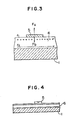
- a high-voltage conductor 4 is supported on an insulating support 2 in a metallic tubular member or a grounded tank 1 hermetically sealed with an insulating gas such as SF 6 .
- the inner peripheral surface of the metallic tubular member 1 is closely covered with an adhesive sheet of insulating layer 6 formed of a high polymeric substance.
- the high polymeric substance forming the insulating layer 6 is an electret which is polarized by being supplied with a DC electric field or injected with charged particles such as ions, thus capable of semi-permanently holding the electron charges therein.
- a method of fabricating such an electret is described in "Corona Poling of Polyvinyldenef- luoride", by R.
- Conductive particles 5,5', 5" which fall and stay on an insulating layer 6 are attracted to the surface of the insulating layer 6 under a strong electrostatic force such as coulomb force caused by the surface charges formed on the insulating layer 6.
- the insulating layer 6 is required to satisfy the relation between the electrostatic attraction force Fb, the gravity Fm of the particles, and the electrostatic buoyancy Fa acting on the particles (Fa ⁇ Q.Es, where Q: Supplied amount of charges, and Es: The electric field on the interior surface of the tubular member 1).
- Fb depends on the surface charge density a formed by the charges held in the insulating layer, and therefore, it is possible to obtain Fb satisfying equation (1) by increasing the amount of o.
- the amount of the charges held internally in the insulating layer can be easily increased by the amount of injection of ions or the like at the time of fabrication of the electret, or what is called the magnitude of the intensity of the DC electric field.
- the efficiency of forming the internally-held charges also depends on the orientation of dipoles attached to molecules in the material making up the insulating layer. This function is effectively displayed by such a high polymeric material as polyvinylidene fluoride or polypropylene suitable for the electret as the material forming the insulating layer 6.
- the above-mentioned high polymeric material if provided in a sheet, can be conveniently handled on the one hand and facilitates the installation in the apparatus on the other hand, thus making the apparatus more economical.
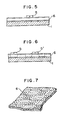
- Fig. 4 or 5 shows the case in which a positive or negative single- pole electrode is formed over the entire area of the surface of the insulating layer.
- the insulating layer may be divided into a plurality of regions 6' where positive and negative charges are mixed with each other in such a manner that the polarities of the surface charges of adjacent regions are opposite to each other, so that the attraction force may be effected by particles of any polarity, as shown in the second embodiment of Figs. 6 and 7.
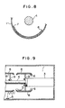
- Fig. 8 shows a third embodiment for forming the insulating layer.
- a metallic insulation layer base plate 7 on which an electret material 6 is laid in advance is arranged as an insulating layer along the internal periphery of a tubular member 1.
- the insulating layer can be processed into an electret by an exclusive device prepared outside of the apparatus, and therefore the processes are greatly simplified, the processing accuracy is improved, and easier installation on the apparatus becomes possible.
- a reticular material or a material having a plurality of punched holes may be used as the insulating layer base plate 7 to reduce the contact area between the electret material 6 and the insulating layer base plate 7 while at the same time conducting the tube-sealed gas between the internal surraces of the tubular member 1 and the insulating layer base plate 7.
- voids which otherwise would be liable to develop between the electret material 6 and the insulating layer base plate 7 are not formed, thereby making it possible to eliminate the disturbance of the polarization orientation of the surface charges of the insulating layer which would otherwise be caused by the partial discharge in the voids.
- the effect of the present invention can be fully achieved if the insulating layer according to the second or third embodiment is formed only at a part where particles are liable to fall and stay.
- an insulating layer 6 making up an electret material is formed on the internal surface of the electric field-relaxing shield 8 in the low-intensity electric field.
- the particles existent on the internal surface of the tubular member 1 approach and intrude into the internal surface of the shield 8 by vibrations or like, the particles are attracted to the shield 8, so that the particle can not fly out of the shield 8. Therefore, the particles are not attached to the insulating spacer 3 or the like supported at the end of the tubular member, thus preventing the insulation of the apparatus from being decreased.
- the shield 8 is supported on the insulating spacer 3 by a shield support 9.
- the attenuation of the charges held by the electret which is a problem generally posed, is avoided by this construction in which the insulating layer 6, that is, the electret material, is arranged on the internal surface of the shield 8 in a low-intensity electric field in the manner shown in a fourth embodiment of the present invention.
- the attenuation (a) of the charges held by the insulating layer arranged on low-voltage side is smaller than the attenuation (b) of the charges held by the insulating layer arranged on high-voltage side as shown in Fig. 10.
- the insulating layer arranged on the low-voltage side thus remains effective for longer than several decades.
- the force which the electret has for attracting the particles is affected by the amount of the surface charges, that is, the surface potential of the electret.
- the abscissa represents the surface potential of the electret
- the ordinate the relative value E LO of the intensity of the electric field attracting the particles with the surface potential of zero as a reference.
- E LO effective for attracting the particles was obtained when the surface potential of the electret is 1 KV or higher.
- E LO increases in proportion to the surface potential
- the surface potential takes a maximum value where the electret layer is not subjected to dielectric breakdown.
- the maximum value of the surface potential is 3.5 KV.
- three electret layers are deposited on the internal surface of the metallic tubular member 1.
- the surfaces of these three electret layers facing each other have charges of the same polarity.
- the hand or other parts of the worker may touch an electret layer and the resulting discharge may reduce the surface potential of the particular electret layer during the work after arrangement of the electret layers on the internal surface of the tubular member 1. It is possible to secure the required surface potential by removing the uppermost electret layer which is likely to have decreased in surface potential, after assembly processes of the apparatus. The electret layer thus removed may of course be used again.
- the electret shown in three layers in Fig. 12 may alternatively be in two or four or more layers.
- the surfaces of the three electret layers formed on the internal surface of a metallic tubular member 1 facing each other carry charges of opposite polarities.
- the surface potential is thus capable of being adjusted by the number of electret layers formed. If each layer has a surface potential of 1 KV, for instance, three layers produce a total surface potential of 3 KV and four layers a total of 4 KV.
- the insulating layer may be taken out of the apparatus before the operation of the apparatus.
- a method of assemblying a gas-insulated electric apparatus according to the present invention will be explained below with reference to a gas-insulated circuit breaker shown in Fig. 14 as an example of the apparatus.
- a grounded tank 1 contains a couple breaker units including a movable electrode 10 and a fixed electrode 11 which are supported insulated from the grounded tank 1 by insulating supports 3. Although a couple of such breaker units are provided in the example shown, any number of breaker units may be provided.
- an insulation control rod 12 is driven by an external command, the movable electrode 10 is energized through a link means built in a mechanism 13 thereby to open the electrodes 10 and 11, so that a gas is blown against the arc generated by separation of the electrodes 10 and 11, from a nozzle 14 around the movable electrode 10.
- a shield electrode 8 for relaxing the electric field intensity is mounted around the movable electrode 10 and the fixed electrode 11.
- the fixed electrode 11 is connected with a contactor 15, which in turn is connected with a conductor of another gas-insulated apparatus by which the opening 16 is closed.
- the grounded tank 1 of the breaker constructed in the manner as described above is filled with an SF 6 gas or like before operation.
- the circuit breaker of this construction generates not a small quantity of conductive particles by mechanical vibration or electrical stress such as an operation test of movable parts or an insulation test in the final or other assembly process, and by vibration due to the transport of the apparatus to the site of operation.
- Such conductive particles though small in amount, are generated at a fastening part 21 which is fastened by bolts 17 in mounting the shield 8 shown.
- Conductive particles are also generated from sliding parts 8, 9 during the operation test of the movable parts.
- the conductive particles thus generated fall not always on the bottom of the grounded tank 20 but may intrude into the shield 8 or into the corners of the grounded tank 20.
- sheets of electret material 6 are laid in the circuit breaker under assembly as shown in the lower right part of the drawing.
- the electret material is also laid on the other parts of the breaker not shown in the drawing.
- the electret materials 6 cover the outer surface of the insulating support 3 in order to keep off the conductive particles from the surface of the insulating support 3.
- the electret material 6 is also arranged on the lower part of the shield 8 to protect the shield 8 from the conductive particles, which if intruded into the shield 8, would be difficult to remove.
- the electret material 6 is further laid on the lower half surface of the grounded tank 1 to capture the conductive particles that have fallen.
- the conductive particles that are generated at the time of assembly or an operation test of movable parts are attracted by the electrostatic attraction force of the electret materials.
- the electret materials are taken out of the apparatus at least before the operation of the breaker, such as at the time of final sealing from the atmosphere, for example, thereby removing the fine conductive particles which have so far been difficult to remove.
- These electret materials have a very long discharge time constant of the charges and therefore is capable of holding the static electricity semi-permanently. In other words, unlike an ordinarily-charged material, these materials display a full dust-collecting ability even during the rainy season when humidity is comparatively high.
- the electret materials, once taken out, can be cleaned separately thereby to maintain the static electricity.
- the present invention is also applicable to a gas-insulated bus with a conductor supported by an insulating support in a grounded tank.
- the electret materials are cut into pieces of such a size as to be capable of being recovered by vacuum cleaner and laid in the grounded tank, the materials can be recovered by vacuum cleaner at least before operation.
- the electrostatic electret materials may be placed in the grounded tank before the operation test of the movable parts. Alternatively, the electret materials may be taken out immediately after the movable-part operation test or after transportation of the apparatus to the site of operation.
Landscapes
- Chemical & Material Sciences (AREA)
- Oil, Petroleum & Natural Gas (AREA)
- Installation Of Bus-Bars (AREA)
- Laminated Bodies (AREA)
Claims (15)
Applications Claiming Priority (4)
| Application Number | Priority Date | Filing Date | Title |
|---|---|---|---|
| JP59076500A JPS60223414A (ja) | 1984-04-18 | 1984-04-18 | ガス絶縁電気機器 |
| JP76500/84 | 1984-04-18 | ||
| JP59184494A JPS6166509A (ja) | 1984-09-05 | 1984-09-05 | ガス絶縁機器の組立方法 |
| JP184494/84 | 1984-09-05 |
Publications (3)
| Publication Number | Publication Date |
|---|---|
| EP0159664A2 EP0159664A2 (de) | 1985-10-30 |
| EP0159664A3 EP0159664A3 (en) | 1987-02-25 |
| EP0159664B1 true EP0159664B1 (de) | 1990-07-04 |
Family
ID=26417648
Family Applications (1)
| Application Number | Title | Priority Date | Filing Date |
|---|---|---|---|
| EP85104669A Expired - Lifetime EP0159664B1 (de) | 1984-04-18 | 1985-04-17 | Gasisoliertes elektrisches Gerät und dazugehöriges Zusammensetzungsverfahren |
Country Status (5)
| Country | Link |
|---|---|
| US (1) | US4564721A (de) |
| EP (1) | EP0159664B1 (de) |
| KR (1) | KR900001481B1 (de) |
| CA (1) | CA1231146A (de) |
| DE (1) | DE3578514D1 (de) |
Families Citing this family (12)
| Publication number | Priority date | Publication date | Assignee | Title |
|---|---|---|---|---|
| DE4120309A1 (de) * | 1991-06-20 | 1992-12-24 | Asea Brown Boveri | Hochspannungsanlage |
| US6162535A (en) * | 1996-05-24 | 2000-12-19 | Kimberly-Clark Worldwide, Inc. | Ferroelectric fibers and applications therefor |
| US6759356B1 (en) | 1998-06-30 | 2004-07-06 | Kimberly-Clark Worldwide, Inc. | Fibrous electret polymeric articles |
| US6573205B1 (en) | 1999-01-30 | 2003-06-03 | Kimberly-Clark Worldwide, Inc. | Stable electret polymeric articles |
| EP1306954B1 (de) * | 2001-10-29 | 2011-07-27 | ABB Research Ltd. | GIS-Stützisolator mit integrierter Barriere |
| US8189323B2 (en) * | 2008-12-02 | 2012-05-29 | Mitsubishi Electric Corporation | Gas-insulated switchgear apparatus |
| EP2456033B1 (de) * | 2009-07-17 | 2020-04-01 | Mitsubishi Electric Corporation | Gasisolierter bus |
| US20110226503A1 (en) * | 2010-03-17 | 2011-09-22 | Bolin Philip C | Gas insulated busbar particle trap |
| CN101887003B (zh) | 2010-06-29 | 2016-06-08 | 上海杰远环保科技有限公司 | 一种微粒测量装置及其测量方法 |
| US8597405B2 (en) | 2011-08-23 | 2013-12-03 | Empire Technology Development Llc | Self-cleaning electret filter |
| DK3098919T3 (da) * | 2014-01-22 | 2020-06-22 | Mitsubishi Electric Corp | Gasisoleret elektrisk apparat |
| KR101605601B1 (ko) * | 2014-02-07 | 2016-03-22 | 현대중공업 주식회사 | 고정부의 길이를 축소한 가스절연 개폐장치의 차단기 |
Family Cites Families (5)
| Publication number | Priority date | Publication date | Assignee | Title |
|---|---|---|---|---|
| CH570720A5 (de) * | 1974-04-17 | 1975-12-15 | Bbc Brown Boveri & Cie | |
| JPS5271619A (en) * | 1975-12-12 | 1977-06-15 | Toshiba Corp | Oil-filled electric machines |
| JPS55136811A (en) * | 1979-04-12 | 1980-10-25 | Mitsubishi Electric Corp | Gas insulated electric device |
| US4330682A (en) * | 1980-11-14 | 1982-05-18 | The United States Of America As Represented By The Department Of Energy | Hybrid particle traps and conditioning procedure for gas insulated transmission lines |
| US4343964A (en) * | 1981-01-19 | 1982-08-10 | The United States Of America As Represented By The United States Department Of Energy | Adhesive coated electrical apparatus having sublimable protective covering and an assembly method |
-
1985
- 1985-04-11 KR KR1019850002422A patent/KR900001481B1/ko not_active Expired
- 1985-04-17 US US06/724,200 patent/US4564721A/en not_active Expired - Lifetime
- 1985-04-17 DE DE8585104669T patent/DE3578514D1/de not_active Expired - Lifetime
- 1985-04-17 EP EP85104669A patent/EP0159664B1/de not_active Expired - Lifetime
- 1985-04-17 CA CA000479399A patent/CA1231146A/en not_active Expired
Also Published As
| Publication number | Publication date |
|---|---|
| EP0159664A3 (en) | 1987-02-25 |
| EP0159664A2 (de) | 1985-10-30 |
| KR850007325A (ko) | 1985-12-02 |
| US4564721A (en) | 1986-01-14 |
| KR900001481B1 (ko) | 1990-03-12 |
| CA1231146A (en) | 1988-01-05 |
| DE3578514D1 (de) | 1990-08-09 |
Similar Documents
| Publication | Publication Date | Title |
|---|---|---|
| EP0159664B1 (de) | Gasisoliertes elektrisches Gerät und dazugehöriges Zusammensetzungsverfahren | |
| US3898408A (en) | Circuit interrupter with improved trap for removing particles from fluid insulating material | |
| EP2405550B1 (de) | Luftdicht isolierte vorrichtung | |
| KR102671297B1 (ko) | 클리닝 장치 | |
| US4064353A (en) | Gas insulated transmission line with particle trap | |
| JPH06237517A (ja) | 密閉導体装置 | |
| US4667061A (en) | Gas insulated apparatus with internal coated insulation layer of high dielectric constant | |
| CA1177918A (en) | Hybrid particle traps and conditioning procedure for gas insulated transmission lines | |
| US4433203A (en) | Electrical insulator with water-repellent oil-bleeding insulation bands | |
| JPH0279711A (ja) | ガス絶縁容器 | |
| CN85102947B (zh) | 气体绝缘电气设备及其装配方法 | |
| JPS6023569B2 (ja) | ガス絶縁電気装置 | |
| JPH06244270A (ja) | 静電吸着装置 | |
| GB2129206A (en) | Thyratron grid arrangement | |
| EP1091377B1 (de) | Vakuumauslassvorrichtung eines Vakuumschalters | |
| JPH02106B2 (de) | ||
| JP2760488B2 (ja) | 送電線用避雷装置 | |
| JPH07288071A (ja) | 開閉器 | |
| CA2137104A1 (en) | High voltage installation | |
| JPS6134809Y2 (de) | ||
| US7593207B2 (en) | Gas-insulated switchgear assembly or component of a gas-insulated switchgear assembly having an outdoor bushing | |
| DE4104922A1 (de) | Metallgekapselte gasisolierte hochspannungsanlage | |
| JPH04192234A (ja) | 真空遮断器 | |
| ELIZONDO et al. | Microstack insulator for flashover inhibition, phase 2(Technical Report, 27 Mar. 1989- 31 Mar. 1991) | |
| JPH0699099A (ja) | 電気集塵エレメント |
Legal Events
| Date | Code | Title | Description |
|---|---|---|---|
| PUAI | Public reference made under article 153(3) epc to a published international application that has entered the european phase |
Free format text: ORIGINAL CODE: 0009012 |
|
| AK | Designated contracting states |
Designated state(s): CH DE LI |
|
| PUAL | Search report despatched |
Free format text: ORIGINAL CODE: 0009013 |
|
| AK | Designated contracting states |
Kind code of ref document: A3 Designated state(s): CH DE LI |
|
| 17P | Request for examination filed |
Effective date: 19870226 |
|
| 17Q | First examination report despatched |
Effective date: 19891023 |
|
| GRAA | (expected) grant |
Free format text: ORIGINAL CODE: 0009210 |
|
| AK | Designated contracting states |
Kind code of ref document: B1 Designated state(s): CH DE LI |
|
| REF | Corresponds to: |
Ref document number: 3578514 Country of ref document: DE Date of ref document: 19900809 |
|
| PLBE | No opposition filed within time limit |
Free format text: ORIGINAL CODE: 0009261 |
|
| STAA | Information on the status of an ep patent application or granted ep patent |
Free format text: STATUS: NO OPPOSITION FILED WITHIN TIME LIMIT |
|
| 26N | No opposition filed | ||
| PGFP | Annual fee paid to national office [announced via postgrant information from national office to epo] |
Ref country code: CH Payment date: 20030326 Year of fee payment: 19 |
|
| PGFP | Annual fee paid to national office [announced via postgrant information from national office to epo] |
Ref country code: DE Payment date: 20030605 Year of fee payment: 19 |
|
| PG25 | Lapsed in a contracting state [announced via postgrant information from national office to epo] |
Ref country code: LI Free format text: LAPSE BECAUSE OF NON-PAYMENT OF DUE FEES Effective date: 20040430 Ref country code: CH Free format text: LAPSE BECAUSE OF NON-PAYMENT OF DUE FEES Effective date: 20040430 |
|
| PG25 | Lapsed in a contracting state [announced via postgrant information from national office to epo] |
Ref country code: DE Free format text: LAPSE BECAUSE OF NON-PAYMENT OF DUE FEES Effective date: 20041103 |
|
| REG | Reference to a national code |
Ref country code: CH Ref legal event code: PL |