EP0157982A2 - Method and apparatus for blasting electrically detonating primers - Google Patents
Method and apparatus for blasting electrically detonating primers Download PDFInfo
- Publication number
- EP0157982A2 EP0157982A2 EP84306973A EP84306973A EP0157982A2 EP 0157982 A2 EP0157982 A2 EP 0157982A2 EP 84306973 A EP84306973 A EP 84306973A EP 84306973 A EP84306973 A EP 84306973A EP 0157982 A2 EP0157982 A2 EP 0157982A2
- Authority
- EP
- European Patent Office
- Prior art keywords
- bus wire
- high frequency
- frequency current
- detonating
- conductors
- Prior art date
- Legal status (The legal status is an assumption and is not a legal conclusion. Google has not performed a legal analysis and makes no representation as to the accuracy of the status listed.)
- Granted
Links
Images


Classifications
-
- F—MECHANICAL ENGINEERING; LIGHTING; HEATING; WEAPONS; BLASTING
- F41—WEAPONS
- F41A—FUNCTIONAL FEATURES OR DETAILS COMMON TO BOTH SMALLARMS AND ORDNANCE, e.g. CANNONS; MOUNTINGS FOR SMALLARMS OR ORDNANCE
- F41A19/00—Firing or trigger mechanisms; Cocking mechanisms
- F41A19/58—Electric firing mechanisms
- F41A19/63—Electric firing mechanisms having means for contactless transmission of electric energy, e.g. by induction, by sparking gap
Definitions
- the present invention generally relates to technique for electrically blasting percussion powders of detonating primers, and more particularly to a method and an apparatus for blasting electrically a number of detonating primers electromagnetically coupled with a bus wire via magnetic cores by supplying a high frequency electric current to the bus wire.
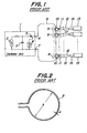
- Fig. 1 illustrates a known blasting apparatus by means of which a plurality of detonating primers electromagnetically coupled with a bus wire serially are electrically exploded.
- the apparatus comprises an oscillator unit 1 including a voltage supply source 2 such as a battery, a capacitor 3 charged by the battery 2, a trigger circuit 4 and a silicon controlled rectifier-5 which can be switched on by the trigger circuit 4.
- a voltage supply source 2 such as a battery
- a capacitor 3 charged by the battery 2 a trigger circuit 4 and a silicon controlled rectifier-5 which can be switched on by the trigger circuit 4.
- the oscillator unit 1 produces a pulsatory voltage having a large amplitude across outputs 6 and 7 to which a loop-like bus wire 8 is connected.
- a pulsatory current flows through the loop-like bus wire 8.
- a number of transformer units 9 each having a magnetic core 10 and a secondary winding 11 wound on the core.
- the bus wire 8 is passed as a primary winding.
- leg wires 12 and 13 of a number of detonating primers 14 which are coupled with blasting explosives 15.
- the magnetic core 10 is liable to be large in size and heavy in weight. Therefore, it is difficult or at least cumbersome to carry and handle such large and heavy magnetic cores.
- the number of detonating primers 14 to be coupled with the same and single bus wire 8 often / amounts to several tens to several hundreds.
- the bus wire 8 should be passed through the ring-shaped magnetic cores 10 at places at which the explosion is to be effected.
- the operation for passing the bus wire through a number of cores is apparently very cumbersome.
- the bus wire is liable to become entangled with the magnetic cores 10.
- the leg wires 12, 13 of detonating primer 14 are subjected to a strong tensile force and unexpected shock might be applied to the detonating primer. This is very undesirable in the view point of the safety.
- the detonating primer 14 might be pulled out of the blasting explosive 15.
- the bus wire 8 forms a loop.
- the bus wire 8 has a diameter a and the loop has a diameter b as schematically illustrated in Fig. 2.
- an impedance Z of the loop formed by the bus wire 8 is expressed by the following equation, where f is a frequency of the current flowing through the bus wire 8, and N is the number of turns. From this equation, it is apparent that when an inductance of the loop represented by 4 ⁇ bN 2 (log -2)10 -7 is changed, the impedance Z is also varied. The inductance of the loop will be changed in accordance with the configuration of the loop and the loop configuration will be varied in accordance with the fact how to lead or extend the bus wire 8.
- the loop of the bus wire will be changed in accordance with conditions of environment. Therefore, in the known method, the frequency of the output of the oscillator unit 1 has to be adjusted in accordance with the variation of the impedance of the bus wire 8 forming the loop, and therefore it is difficult to attain the stable operation under various conditions.
- the present invention has for its object to provide an improved method of blasting electrically a number of detonating primers having loops electromagnetically coupled with a bus wire by means of magnetic cores, in which a pulsatory current having a-sufficient amplitude for exploding percussion powders of the detonating primers can be electromagnetically induced by means of magnetic cores through which the bus wire can be easily and correctly passed, while an impedance of the bus wire can be remained substantially unchanged in regardless of conditions of the bus wire.
- a method of blasting electrically a plurality of detonating primers by supplying an electric current through a bus wire with which leg wires of detonating primers are electromagnetically coupled by means of a plurality of magnetic cores comprises
- the present invention also relates to an apparatus for electrically blasting a number of detonating primers having loops electromagnetically coupled with a bus wire by means of magnetic cores and has for its object to provide a novel and useful apparatus which can positively explode the detonating primers by using small and light magnetic cores and can be made simple in construction and small in size.
- an apparatus for blasting electrically a plurality of detonating primers by supplying an electric current through a bus wire with which leg wires of detonating primers are electromagnetically coupled by means of a plurality of magnetic cores comprises
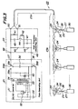
- Fig. 3 is a circuit diagram showing an embodiment of the electric blasting apparatus according to the invention.
- the apparatus comprises a pulse generating unit 21, a high frequency converting unit 22 connected to the pulse generating unit 21, a bus wire 23 connected to the high frequency converting unit 22 and a number of transforming units 24 including magnetic cores 25 electromagnetically coupled with the bus wire 23.
- the transforming units 24 further comprise loops 26 which are electromagnetically coupled with the magnetic cores 25 and are connected to detonating primers 27 by means of leg wires 28 and 29.
- the detonating primers 27 are coupled with explosives 30 in any known manner.
- the pulse generating circuit 21 comprises a DC/DC converter 31 formed as a known booster unit including a transistor 32, a transformer 33 and a diode 34.
- the DC/DC converter 31 converts a relatively low D.C. voltage of, for instance 6 Volts of a battery 35 into a high voltage of for instance 350 volts which appears across a charging and discharging capacitor 36 which is selectively connectable either to the DC/DC converter 31 or to outputs 37 and 38 of the pulse generating unit 21 by means of cooperative switches 39A and 39B.
- the switching arm of switch 39A is connected to a contact 39a to charge the capacitor 36.
- a voltage indication lamp 40 is lit.
- the pulse generating unit 21 has been ready for producing the voltage pulse having a sufficient amplitude for blasting the detonating primers 27.
- the switching arm of switch 39A is changed into a contact 39b as illustrated in Fig. 3, the capacitor 36 starts to discharge.
- the pulse generating unit 21 produces across its outputs 37 and 38 a pulsatory output voltage of a large amplitude as illustrated in Fig. 4A.
- the high frequency converting unit 22 comprises tuning coils 41, 42, tuning capacitor 43, transistor 44, bias resistors 45, 46 and bias capacitor 47, these elements forming a well known oscillating circuit.
- the pulsatary voltage applied to inputs 48 and 49 of the high frequency converting unit 22 is converted thereby into a high frequency voltage illustrated in Fig. 4B.
- the high frequency voltage appears across outputs 50 and 51 of the high frequency converting unit 22, and thus a corresponding high frequency current flows through the bus wire 23 connected across the outputs 50 and 51.
- the high frequency voltage lasts for about 20 mS and has the maximum peak value of about 900 V.
- the frequency of the high frequency voltage is determined by the inductances of the tuning coil 41 and bus wire 23 and the capacitance of the tuning capacitor 43 and may be set to a value within a range from 50 KHz to 1 MHz, preferably 50 KHz to 200 KHz.
- the bus wire 23 has a substantially constant impedance.
- the bus wire 23 according to the invention may be formed by a pair of parallel conductors whose distal ends are connected to each other.
- the impedance Zo of the bus wire 23 is expressed as follows. wherein D is a distance between the parallel conductors and d is a diameter of the conductors. From the above equation, it is apparent that the impedance Zo of the bus wire 23 according to the invention is remained constant as long as the distance D and diameter d are constant. The same may be applied to the bus wire which is formed by a pair of twisted conductors whose distal ends are short-circuited.
- said distance D may be an average distance between the two conductors.
- the bus wire 23 is composed of a main bus wire 23a formed by a pair of parallel conductors and a sub bus wire 23b formed by a pair of twisted conductors having one ends connected to the parallel conductors of the main bus wire 23a and the other ends connected to each other. It should be noted the main bus--wire 23a is used repeatedly, but the sub bus wire 23b is broken into peaces upon explosion.
- the bus wire 23 since use is made of the bus wire 23 having a substantially constant impedance in regardless of the conditions of the bus wire, i.e. how to lead or extend the bus wire, it is not necessary to adjust the operation frequency of the high frequency converting unit 22 and the stable explosion can be always attained. Further, since it is possible to use always the high frequency current, the magnetic cores 25 can be made small in size and light in weight.
- the bus wire 23 is electromagnetically coupled with a number of the transforming units 24 at many desired positions.
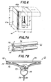
- the transforming unit 24 comprises a magnetic core 25 having a slit 25a as shown in Fig. 5A.
- the slit 25a has such a dimension that one conductor of the twisted bus wire 23b can be inserted into the magnetic core 25 through the slit 25a in an easy and positive manner.
- the loop 26 connected to the detonating primer 27 can be also inserted into the magnetic core 25 through the slit 25a.
- the loop 26 has been connected to the detonating primer 27 by means of parallel leg wires 28 and 29. In this manner, the loops 26 can be easily and positively passed through the magnetic cores 25.
- the leg wires 28 and 29 of-the detonating primer 27 are not subjected to any undesired tensile force and the detonating primer can be completely protected against unexpected explosion, because it is not necessary to pull the bus wire.
- the capacitor 36 in the pulse generating unit 21 has a capacitance value of 400 pF and the battery voltage of 6 volts is increased up to about 350 volts at the outputs 37 and 38.
- the tuning coils 41 and 42 of the high frequency converting unit 22 have inductances of 45 pH and 5 pH, respectively, the tuning capacitor 43 has a capacitance of 0.047 ⁇ F, the transistor 44 is formed by a switching power transistor of high speed and high tension type, the bias resistors 45 and 46 have resistances of 5 KQ and 50 Q, respectively, and the bias capacitor 47 has a capacitance of 1 pF. Then, the high frequency converting unit 22 produces across its outputs 50 and 51 the high frequency voltage pulse having the maximum peak voltage of about 900 volts and the frequency of 100 KHz to 140 KHz.
- the bus wire 23 is formed by the main bus wire 23a and sub bus wire 23b.
- the main bus wire 23a is consisting of the parallel conductors having a D.C. resistance of 2.4 Q and a length of 100 m. Each conductor has a cross section of 1.25 mm 2 .
- the sub bus wire 23b is formed by the twisted conductors having a D.C. resistance of 5.7 Q, a length of 50 m and a twisting pitch of about 50 mm. Each conductor has a cross section of 0.28 mm 2 .
- the magnetic core 61 comprises a substantially U-shaped main block 61a and a bridge block 6lb which is slidable with respect to the main block 61a as shown by a double headed arrow. That is to say, the main block 6la is fixed to a frame (not shown) made of non-magnetic material such as plastics and the bridge block 61b is slidably secured to the frame. When the bridge block 61b is moved as shown by a chain line, an upper opening of the main block 61a is exposed.
- the main block 61a has a height H of 15 mm, width W of 15 mm and a thickness T of 10 mm.
- the bridge block 61b has height H' of 5 mm.
- the space has a height H" of 10 mm, and a width W of 5 mm.
- the main block 61a and bridge block 6lb are preferably made of ferrite.
- the present example there are prepared forty rectangular magnetic cores 61 shown in Fig. 6 and in a space of each magnetic core are inserted at first five loops 26 of detonating primers 27. Then one conductor of the sub wire 23b is inserted into the space. After that, the space is closed by shifting the bridge block 61b.
- the loop 26 is formed by a conductor having a diameter of 0.45 mm and has a diameter of about 100 mm. Both ends of the loop 26 have been connected to the detonating primer 27 by means of the leg wires 28 and 29 having a length of 1.5 m.
- the loop 26 and leg wires 28, 29 are formed by conductors having insulating coatings applied thereon.
- the detonating primers 27 have the minimum blasting energy of 3 to 4 milli Joules.
- the sub bus wire may be also formed by a parallel wire as shown in Fig. 7A.
- the parallel wire 71 comprises a pair of conductors 72 and 73 having a diameter d of 0.6 mm and being spaced from each other by a distance D of 1 to 2 mm.
- the conductors 72 and 73 are supported in parallel with each other by means of a strip-like insulating member 74.
- the insulating member 74 is partially cut.
- the magnetic core 61 shown in Fig. 6 may be fit into a clip-like frame.
- the bridge block 61b may be secured to a swingable arm of the clip-like frame.
- the slit 25a of the magnetic core 25 may be closed by a bridge piece 25b.
- the bridge piece 25b may be secured to the core 25 by any suitable means such as adhesive agent and adhesive tape, after the conductor of the bus wire 23b and the loop 26 of the detonating primer 27 are inserted into the core 25 through the slit 25a. It has been confirmed experimently that when the frequency of the high frequency current passing through the bus wire is relatively low, it is preferable to close the slit or opening of magnetic core by means of magnetic bridge member. Contrary to this, when the current flowing through the bus wire has a sufficiently high frequency, the slit or opening of magnetic core 25 is not always necessary to be closed by the magnetic bridge member.
- the bus wire does not form the loop and is formed by the twisted wire or parallel wire which has the constant low impedance, the impedance of the bus wire is not changed in regardless of the conditions of the bus wire, and further the impedance of the bus wire is not changed by the frequency of the high frequency current. Therefore, the detonating primers can be always blasted stably. It is apparent that the high frequency converting unit can be simple in construction.
- the bus wire and the loop of the detonating primer can be inserted into the core through the slit or opening in an easy and possitive manner. During this operation, the leg wires of the detonating primer are not subjected to undesired tensile force, and thus any unexpected shock is not applied to the primer.
- the magnetic core can be made small in size and light in weight. Therefore, a number of magnetic cores can be handled and transported easily.
- the bus wire comprises a pair of parallel conductors through which the blasting high frequency current passes in opposite directions, there occurs substantially no antenna effect and thus undesired radiation of electromagnetic wave can be effectively prevented.
Abstract
Description
- The present invention generally relates to technique for electrically blasting percussion powders of detonating primers, and more particularly to a method and an apparatus for blasting electrically a number of detonating primers electromagnetically coupled with a bus wire via magnetic cores by supplying a high frequency electric current to the bus wire.
- Fig. 1 illustrates a known blasting apparatus by means of which a plurality of detonating primers electromagnetically coupled with a bus wire serially are electrically exploded. Such a known apparatus has been described in, for instance Japanese Patent Application Laid-open Publication No. 22,608/74. The apparatus comprises an oscillator unit 1 including a voltage supply source 2 such as a battery, a
capacitor 3 charged by the battery 2, atrigger circuit 4 and a silicon controlled rectifier-5 which can be switched on by thetrigger circuit 4. When thetrigger circuit 4 is actuated, the oscillator unit 1 produces a pulsatory voltage having a large amplitude acrossoutputs 6 and 7 to which a loop-like bus wire 8 is connected. Therefore a pulsatory current flows through the loop-like bus wire 8. To thebus wire 8 are electromagnetically coupled a number oftransformer units 9 each having amagnetic core 10 and a secondary winding 11 wound on the core. Through thecores 10 thebus wire 8 is passed as a primary winding. To both ends of thesecondary windings 11 are connectedleg wires primers 14 which are coupled withblasting explosives 15. When the pulsatory current supplied from the oscillator unit 1 flows through thebus wire 8, pulsatory currents are electromagnetically induced in theleg wires primers 14, and thus the detonatingprimers 14 are exploded primarily. Then theexplosives 15 coupled with the detonatingprimers 14 are blasted secondarily. - In the above explained known blasting method, since the current flowing through the
bus wire 8, i.e. the primary winding of thetransformer unit 9 has several hundred heltzs, themagnetic core 10 is liable to be large in size and heavy in weight. Therefore, it is difficult or at least cumbersome to carry and handle such large and heavy magnetic cores. In this connection, it should be noted that the number of detonatingprimers 14 to be coupled with the same andsingle bus wire 8 often/amounts to several tens to several hundreds. - Moreover, in the known method, it is necessary to connect the
leg wires primer 14 to thesecondary winding 11 which has been previously wound on themagnetic core 10. This requires very cumbersome operation of a user. - Furthermore, in the known method, the
bus wire 8 should be passed through the ring-shapedmagnetic cores 10 at places at which the explosion is to be effected. The operation for passing the bus wire through a number of cores is apparently very cumbersome. Particularly, when the number ofmagnetic cores 10 which have been passed through thebus wire 8 is increased, the bus wire is liable to become entangled with themagnetic cores 10. In order to avoid this, it is necessary to pull or draw thebus wire 8 rather strongly. However, when thebus wire 8 is pulled strongly, theleg wires primer 14 are subjected to a strong tensile force and unexpected shock might be applied to the detonating primer. This is very undesirable in the view point of the safety. Moreover, in an extreme case the detonatingprimer 14 might be pulled out of the blasting explosive 15. - In the known method, the
bus wire 8 forms a loop. Now it is assumed that thebus wire 8 has a diameter a and the loop has a diameter b as schematically illustrated in Fig. 2. Then an impedance Z of the loop formed by thebus wire 8 is expressed by the following equation, where f is a frequency of the current flowing through thebus wire 8, and N is the number of turns.

bus wire 8. Further, in case of effecting the explosion under the sea, the loop of the bus wire will be changed in accordance with conditions of environment. Therefore, in the known method, the frequency of the output of the oscillator unit 1 has to be adjusted in accordance with the variation of the impedance of thebus wire 8 forming the loop, and therefore it is difficult to attain the stable operation under various conditions. - The present invention has for its object to provide an improved method of blasting electrically a number of detonating primers having loops electromagnetically coupled with a bus wire by means of magnetic cores, in which a pulsatory current having a-sufficient amplitude for exploding percussion powders of the detonating primers can be electromagnetically induced by means of magnetic cores through which the bus wire can be easily and correctly passed, while an impedance of the bus wire can be remained substantially unchanged in regardless of conditions of the bus wire.
- It is another object of the invention to provide a method of electrically blasting a number of detonating primers electromagnetically coupled with a bus wire via magnetic cores, in which a high frequency can pass through the bus wire, and thus small and light magnetic cores can be used, while sufficiently large energy can be supplied to the detonating primers.
- According to the invention, a method of blasting electrically a plurality of detonating primers by supplying an electric current through a bus wire with which leg wires of detonating primers are electromagnetically coupled by means of a plurality of magnetic cores, comprises
- inserting loops connected to said leg wires of detonating primers into said magnetic cores through openings thereof;
- inserting a plurality of portions of one conductor of said bus wire into the respective magnetic cores through openings thereof, the other conductor of the bus wire being spaced from said one conductor by a substantially constant distance so that the bus wire has a substantially constant impedance; and
- flowing a high frequency current through said bus wire to induce in the respective loops a high frequency secondary current due to a transforming action of said magnetic cores, whereby said induced high frequency currents are supplied to the respective detonating primers through the leg wires to blast the detonating primers.
- The present invention also relates to an apparatus for electrically blasting a number of detonating primers having loops electromagnetically coupled with a bus wire by means of magnetic cores and has for its object to provide a novel and useful apparatus which can positively explode the detonating primers by using small and light magnetic cores and can be made simple in construction and small in size.
- According to the invention, an apparatus for blasting electrically a plurality of detonating primers by supplying an electric current through a bus wire with which leg wires of detonating primers are electromagnetically coupled by means of a plurality of magnetic cores, comprises
- means for generating a pulsatory high voltage;
- means for converting the pulsatory high voltage into a high frequency current;
- a bus wire comprising a pair of conductors which are separated from each other substantially by a constant distance over its whole length and have distal ends connected to each other, so that said high frequency current passes through said conductors in opposite directions, said bus wire having a substantially constant impedance;
- a plurality of magnetic cores each having an opening through which one of said conductors of the bus wire is inserted into the magnetic core; and
- a plurality of loops each connected to a respective detonating primer via leg wires, said loop being inserted into the magnetic core through said opening.
- The invention will now be described in greater detail with reference to the accompanying drawings, wherein:
- Fig. 1 is a circuit diagram showing a known apparatus for blasting electrically detonating primers;
- Fig. 2 is a schematic diagram showing a loop formed by a bus wire of the known apparatus;
- Fig. 3 is a circuit diagram illustrating an embodiment of the electric blasting apparatus according to the invention;
- Figs. 4A and 4B are waveforms for explaining the operation of the apparatus shown in Fig. 3;
- Figs. 5A and 5B are perspective views illustrating two embodiments of a magnetic core according to the invention;
- Fig. 6 is a perspective view showing another embodiment of the magnetic core according to the invention; and
- Figs. 7A and 7B are perspective views depicting an embodiment of a bus wire according to the invention.
- Fig. 3 is a circuit diagram showing an embodiment of the electric blasting apparatus according to the invention. The apparatus comprises a
pulse generating unit 21, a high frequency converting unit 22 connected to thepulse generating unit 21, abus wire 23 connected to the high frequency converting unit 22 and a number of transformingunits 24 includingmagnetic cores 25 electromagnetically coupled with thebus wire 23. The transformingunits 24 further compriseloops 26 which are electromagnetically coupled with themagnetic cores 25 and are connected to detonatingprimers 27 by means ofleg wires primers 27 are coupled withexplosives 30 in any known manner. - The
pulse generating circuit 21 comprises a DC/DC converter 31 formed as a known booster unit including atransistor 32, atransformer 33 and a diode 34. The DC/DC converter 31 converts a relatively low D.C. voltage of, forinstance 6 Volts of abattery 35 into a high voltage of for instance 350 volts which appears across a charging and dischargingcapacitor 36 which is selectively connectable either to the DC/DC converter 31 or to outputs 37 and 38 of thepulse generating unit 21 by means ofcooperative switches switch 39A is connected to a contact 39a to charge thecapacitor 36. When thecapacitor 36 has been charged to a sufficient level, avoltage indication lamp 40 is lit. Then, a user can know that thepulse generating unit 21 has been ready for producing the voltage pulse having a sufficient amplitude for blasting the detonatingprimers 27. When the switching arm ofswitch 39A is changed into acontact 39b as illustrated in Fig. 3, thecapacitor 36 starts to discharge. In this manner, thepulse generating unit 21 produces across itsoutputs 37 and 38 a pulsatory output voltage of a large amplitude as illustrated in Fig. 4A. - The high frequency converting unit 22 comprises tuning coils 41, 42, tuning
capacitor 43,transistor 44,bias resistors bias capacitor 47, these elements forming a well known oscillating circuit. The pulsatary voltage applied toinputs outputs bus wire 23 connected across theoutputs coil 41 andbus wire 23 and the capacitance of the tuningcapacitor 43 and may be set to a value within a range from 50 KHz to 1 MHz, preferably 50 KHz to 200 KHz. - According to the invention, the
bus wire 23 has a substantially constant impedance. This will be explained hereinbelow. Thebus wire 23 according to the invention may be formed by a pair of parallel conductors whose distal ends are connected to each other. In such a parallel line, the impedance Zo of thebus wire 23 is expressed as follows.
bus wire 23 according to the invention is remained constant as long as the distance D and diameter d are constant. The same may be applied to the bus wire which is formed by a pair of twisted conductors whose distal ends are short-circuited. In this case, said distance D may be an average distance between the two conductors. In the embodiment shown in Fig. 3, thebus wire 23 is composed of amain bus wire 23a formed by a pair of parallel conductors and asub bus wire 23b formed by a pair of twisted conductors having one ends connected to the parallel conductors of themain bus wire 23a and the other ends connected to each other. It should be noted the main bus--wire 23a is used repeatedly, but thesub bus wire 23b is broken into peaces upon explosion. - According to the invention, since use is made of the
bus wire 23 having a substantially constant impedance in regardless of the conditions of the bus wire, i.e. how to lead or extend the bus wire, it is not necessary to adjust the operation frequency of the high frequency converting unit 22 and the stable explosion can be always attained. Further, since it is possible to use always the high frequency current, themagnetic cores 25 can be made small in size and light in weight. - The
bus wire 23 is electromagnetically coupled with a number of the transformingunits 24 at many desired positions. According to the invention, the transformingunit 24 comprises amagnetic core 25 having aslit 25a as shown in Fig. 5A. Theslit 25a has such a dimension that one conductor of the twistedbus wire 23b can be inserted into themagnetic core 25 through theslit 25a in an easy and positive manner. Further, theloop 26 connected to the detonatingprimer 27 can be also inserted into themagnetic core 25 through theslit 25a. As shown in Fig. 5A, theloop 26 has been connected to the detonatingprimer 27 by means ofparallel leg wires loops 26 can be easily and positively passed through themagnetic cores 25. In this case, theleg wires primer 27 are not subjected to any undesired tensile force and the detonating primer can be completely protected against unexpected explosion, because it is not necessary to pull the bus wire. - When the high frequency current flows through the
bus wire 23 having the constant impedance, secondary high frequency currents are electromagnetically induced in theloops 26 of respective detonatingprimers 27 and the induced currents flows through filaments in the detonating primers via theleg wires primers 27 are blasted effectively, and thenexplosives 30 coupled with the detonatingprimers 27 are also exploded. - Now a numerical example of the electric blasting apparatus according to the invention will be explained in detail.
- In the present example, two hundred detonating primers of
instantaneous explosion type 27 are to be blasted simultaneously. Thecapacitor 36 in thepulse generating unit 21 has a capacitance value of 400 pF and the battery voltage of 6 volts is increased up to about 350 volts at theoutputs capacitor 43 has a capacitance of 0.047 µF, thetransistor 44 is formed by a switching power transistor of high speed and high tension type, thebias resistors bias capacitor 47 has a capacitance of 1 pF. Then, the high frequency converting unit 22 produces across itsoutputs - The
bus wire 23 is formed by themain bus wire 23a andsub bus wire 23b. Themain bus wire 23a is consisting of the parallel conductors having a D.C. resistance of 2.4 Q and a length of 100 m. Each conductor has a cross section of 1.25 mm2. Thesub bus wire 23b is formed by the twisted conductors having a D.C. resistance of 5.7 Q, a length of 50 m and a twisting pitch of about 50 mm. Each conductor has a cross section of 0.28 mm 2. - In the present example, use is made of a rectangular magnetic core shown in Fig. 6 instead of the ring-shaped magnetic core illustrated in Fig. 5A. In Fig. 6, the
magnetic core 61 comprises a substantially U-shaped main block 61a and a bridge block 6lb which is slidable with respect to the main block 61a as shown by a double headed arrow. That is to say, the main block 6la is fixed to a frame (not shown) made of non-magnetic material such as plastics and the bridge block 61b is slidably secured to the frame. When the bridge block 61b is moved as shown by a chain line, an upper opening of the main block 61a is exposed. Then, one conductor of thesub bus wire 23b and theloop 26 of theprimers 27 can be inserted into a space substantially surrounded by the main block 6la through the exposed opening. After that, the bridge block 61b is moved into the position shown by a solid line to enclose the conductor ofsub bus wire 23b andloop 26 within the space of themagnetic core 61. The main block 61a has a height H of 15 mm, width W of 15 mm and a thickness T of 10 mm. The bridge block 61b has height H' of 5 mm. The space has a height H" of 10 mm, and a width W of 5 mm. The main block 61a and bridge block 6lb are preferably made of ferrite. - In the present example, there are prepared forty rectangular
magnetic cores 61 shown in Fig. 6 and in a space of each magnetic core are inserted at first fiveloops 26 of detonatingprimers 27. Then one conductor of thesub wire 23b is inserted into the space. After that, the space is closed by shifting the bridge block 61b. Theloop 26 is formed by a conductor having a diameter of 0.45 mm and has a diameter of about 100 mm. Both ends of theloop 26 have been connected to the detonatingprimer 27 by means of theleg wires loop 26 andleg wires primers 27 have the minimum blasting energy of 3 to 4 milli Joules. - After sufficient amount of charge has been confirmed to be stored in the
capacitor 36 by theindication lamp 40, when the switching arm ofswitch 39A is changed into thecontact 39b, all the two hundred detonatingprimers 27 andexplosives 30 are completely blasted at a time. - The present invention is not limited to the above mentioned embodiments, but many modifications and alternations can be conceived within the scope of the invention. For instance, the sub bus wire may be also formed by a parallel wire as shown in Fig. 7A. The
parallel wire 71 comprises a pair ofconductors conductors member 74. In case of passing theconductor 73 through themagnetic core 75 as shown in Fig. 7B, the insulatingmember 74 is partially cut. For this purpose, there may be formed slits 76 in the insulatingmember 74 along the longitudinal direction of thebus wire 71. - Further, the
magnetic core 61 shown in Fig. 6 may be fit into a clip-like frame. In this case, the bridge block 61b may be secured to a swingable arm of the clip-like frame. Moreover, as shown in Fig. 5B theslit 25a of themagnetic core 25 may be closed by abridge piece 25b. Thebridge piece 25b may be secured to the core 25 by any suitable means such as adhesive agent and adhesive tape, after the conductor of thebus wire 23b and theloop 26 of the detonatingprimer 27 are inserted into the core 25 through theslit 25a. It has been confirmed experimently that when the frequency of the high frequency current passing through the bus wire is relatively low, it is preferable to close the slit or opening of magnetic core by means of magnetic bridge member. Contrary to this, when the current flowing through the bus wire has a sufficiently high frequency, the slit or opening ofmagnetic core 25 is not always necessary to be closed by the magnetic bridge member. - As explained above, according to the invention, since the bus wire does not form the loop and is formed by the twisted wire or parallel wire which has the constant low impedance, the impedance of the bus wire is not changed in regardless of the conditions of the bus wire, and further the impedance of the bus wire is not changed by the frequency of the high frequency current. Therefore, the detonating primers can be always blasted stably. It is apparent that the high frequency converting unit can be simple in construction.
- Furthermore, since use is made of the magnetic core having the slit or opening, the bus wire and the loop of the detonating primer can be inserted into the core through the slit or opening in an easy and possitive manner. During this operation, the leg wires of the detonating primer are not subjected to undesired tensile force, and thus any unexpected shock is not applied to the primer.
- Moreover, according to the invention since the high frequency current can be alway passed through the bus wire, the magnetic core can be made small in size and light in weight. Therefore, a number of magnetic cores can be handled and transported easily.
- According to the invention, the bus wire comprises a pair of parallel conductors through which the blasting high frequency current passes in opposite directions, there occurs substantially no antenna effect and thus undesired radiation of electromagnetic wave can be effectively prevented.
Claims (15)
Applications Claiming Priority (2)
| Application Number | Priority Date | Filing Date | Title |
|---|---|---|---|
| JP58194118A JPS6086400A (en) | 1983-10-19 | 1983-10-19 | Electric blasting method and electric blasting device |
| JP194118/83 | 1983-10-19 |
Publications (3)
| Publication Number | Publication Date |
|---|---|
| EP0157982A2 true EP0157982A2 (en) | 1985-10-16 |
| EP0157982A3 EP0157982A3 (en) | 1986-12-17 |
| EP0157982B1 EP0157982B1 (en) | 1988-04-20 |
Family
ID=16319213
Family Applications (1)
| Application Number | Title | Priority Date | Filing Date |
|---|---|---|---|
| EP84306973A Expired EP0157982B1 (en) | 1983-10-19 | 1984-10-12 | Method and apparatus for blasting electrically detonating primers |
Country Status (7)
| Country | Link |
|---|---|
| US (1) | US4601243A (en) |
| EP (1) | EP0157982B1 (en) |
| JP (1) | JPS6086400A (en) |
| AU (1) | AU549524B2 (en) |
| CA (1) | CA1218736A (en) |
| DE (1) | DE3470600D1 (en) |
| ZA (1) | ZA847815B (en) |
Cited By (1)
| Publication number | Priority date | Publication date | Assignee | Title |
|---|---|---|---|---|
| CN110500924A (en) * | 2019-08-21 | 2019-11-26 | 杭州国芯科技股份有限公司 | A kind of safe Magnedat and the method for ignition without exposed electrical contact |
Families Citing this family (17)
| Publication number | Priority date | Publication date | Assignee | Title |
|---|---|---|---|---|
| JPS6086400A (en) * | 1983-10-19 | 1985-05-15 | 日本油脂株式会社 | Electric blasting method and electric blasting device |
| JPH0692879B2 (en) * | 1985-06-10 | 1994-11-16 | 旭化成工業株式会社 | Blaster |
| JP2525765B2 (en) * | 1985-12-26 | 1996-08-21 | 旭化成工業株式会社 | Electric blasting device |
| JPS62200199A (en) * | 1986-02-27 | 1987-09-03 | 日本油脂株式会社 | Electromagnetic induction type electric blasting method and cordless detonator used for said method |
| US4825765A (en) * | 1986-09-25 | 1989-05-02 | Nippon Oil And Fats Co., Ltd. | Delay circuit for electric blasting, detonating primer having delay circuit and system for electrically blasting detonating primers |
| JPS63148100A (en) * | 1986-12-10 | 1988-06-20 | 日本油脂株式会社 | Centralized control blasting method and electric firing machine |
| JPH0429269Y2 (en) * | 1987-06-29 | 1992-07-15 | ||
| US4852493A (en) * | 1988-02-12 | 1989-08-01 | The United States Of America As Represented By The United States Department Of Energy | Ferrite core coupled slapper detonator apparatus and method |
| US5117756A (en) * | 1989-02-03 | 1992-06-02 | Atlas Powder Company | Method and apparatus for a calibrated electronic timing circuit |
| US5303495A (en) * | 1992-12-09 | 1994-04-19 | Harthcock Jerry D | Personal weapon system |
| FR2701105B1 (en) * | 1993-02-01 | 1995-04-14 | Giat Ind Sa | Demining device. |
| US5756926A (en) * | 1995-04-03 | 1998-05-26 | Hughes Electronics | EFI detonator initiation system and method |
| US6470803B1 (en) | 1997-12-17 | 2002-10-29 | Prime Perforating Systems Limited | Blasting machine and detonator apparatus |
| AU2002320066B2 (en) | 2001-06-06 | 2004-10-14 | Senex Explosives, Inc | System for the initiation of rounds of individually delayed detonators |
| JP2004350476A (en) * | 2003-05-26 | 2004-12-09 | Vizrotech Co Ltd | Power supply system to expansion cartridge for rock crushing |
| GB201207450D0 (en) * | 2012-04-26 | 2012-06-13 | Secr Defence | An electrical pulse splitter for an explosives system |
| CN111043925B (en) * | 2019-12-12 | 2022-04-01 | 北京中大爆破工程有限公司 | Goaf blasting method |
Citations (3)
| Publication number | Priority date | Publication date | Assignee | Title |
|---|---|---|---|---|
| FR2163021A5 (en) * | 1971-11-23 | 1973-07-20 | Bendix Corp | |
| GB1520036A (en) * | 1976-05-04 | 1978-08-02 | Ml Aviation Co Ltd | Ignition circuits |
| DE2920485A1 (en) * | 1978-05-24 | 1979-11-29 | Ici Ltd | DEVICE AND METHOD FOR ELECTRICAL IGNITION |
Family Cites Families (3)
| Publication number | Priority date | Publication date | Assignee | Title |
|---|---|---|---|---|
| CA1161302A (en) * | 1981-06-26 | 1984-01-31 | Gordon K. Jorgenson | Primer assembly |
| EP0096482B1 (en) * | 1982-06-03 | 1986-11-12 | Imperial Chemical Industries Plc | Apparatus for initiating explosions and method therefor |
| JPS6086400A (en) * | 1983-10-19 | 1985-05-15 | 日本油脂株式会社 | Electric blasting method and electric blasting device |
-
1983
- 1983-10-19 JP JP58194118A patent/JPS6086400A/en active Granted
-
1984
- 1984-10-02 US US06/656,891 patent/US4601243A/en not_active Expired - Fee Related
- 1984-10-04 ZA ZA847815A patent/ZA847815B/en unknown
- 1984-10-09 AU AU34033/84A patent/AU549524B2/en not_active Ceased
- 1984-10-12 EP EP84306973A patent/EP0157982B1/en not_active Expired
- 1984-10-12 CA CA000465305A patent/CA1218736A/en not_active Expired
- 1984-10-12 DE DE8484306973T patent/DE3470600D1/en not_active Expired
Patent Citations (3)
| Publication number | Priority date | Publication date | Assignee | Title |
|---|---|---|---|---|
| FR2163021A5 (en) * | 1971-11-23 | 1973-07-20 | Bendix Corp | |
| GB1520036A (en) * | 1976-05-04 | 1978-08-02 | Ml Aviation Co Ltd | Ignition circuits |
| DE2920485A1 (en) * | 1978-05-24 | 1979-11-29 | Ici Ltd | DEVICE AND METHOD FOR ELECTRICAL IGNITION |
Cited By (2)
| Publication number | Priority date | Publication date | Assignee | Title |
|---|---|---|---|---|
| CN110500924A (en) * | 2019-08-21 | 2019-11-26 | 杭州国芯科技股份有限公司 | A kind of safe Magnedat and the method for ignition without exposed electrical contact |
| CN110500924B (en) * | 2019-08-21 | 2021-06-29 | 杭州国芯科技股份有限公司 | Safety magnetoelectric detonator without exposed electric contact and detonation method |
Also Published As
| Publication number | Publication date |
|---|---|
| US4601243A (en) | 1986-07-22 |
| AU549524B2 (en) | 1986-01-30 |
| CA1218736A (en) | 1987-03-03 |
| AU3403384A (en) | 1985-04-26 |
| JPS6086400A (en) | 1985-05-15 |
| EP0157982A3 (en) | 1986-12-17 |
| JPS6319800B2 (en) | 1988-04-25 |
| DE3470600D1 (en) | 1988-05-26 |
| ZA847815B (en) | 1985-12-24 |
| EP0157982B1 (en) | 1988-04-20 |
Similar Documents
| Publication | Publication Date | Title |
|---|---|---|
| EP0157982B1 (en) | Method and apparatus for blasting electrically detonating primers | |
| US4707619A (en) | Saturable inductor switch and pulse compression power supply employing the switch | |
| GB2136214A (en) | Pulse transformer | |
| CN1011843B (en) | Laser arrangement with high-tension pulse generator and method of generating pulse | |
| EP0597661A1 (en) | Improvements in or relating to an electrical arrangement | |
| US5412254A (en) | High voltage pulse generator | |
| US3450996A (en) | Charged particle pulse accelerator incorporating a tesla coil | |
| US6281603B1 (en) | Pulse line generators | |
| US4409492A (en) | Shock excited pulse transformer | |
| US5157272A (en) | Pulse forming networks | |
| US4768127A (en) | Ignition system | |
| JP2525765B2 (en) | Electric blasting device | |
| US4754703A (en) | Method of electrically blasting detonator and cordless detonator for use in said method | |
| RU2040108C1 (en) | Spiral magnetocumulative generator | |
| US6414581B1 (en) | Air core transformer with coaxial grading shield | |
| RU2218655C2 (en) | Device for receiving and converting electromagnetic energy pulse | |
| JPS62153700A (en) | Electric blasting method | |
| Kravchenko et al. | Compact helical magnetocumulative generator for the formation of powerful high-voltage energy pulses | |
| SU851506A1 (en) | Pulsed nanosecond transformer | |
| RU2164052C2 (en) | Electromagnetic energy pulse generating and converting device | |
| SU790138A2 (en) | Generator | |
| RU2054795C1 (en) | Electromagnetic radiation generator | |
| RU2181925C2 (en) | High-voltage pulse generator | |
| RU2263392C2 (en) | High-voltage pulse generator | |
| SU898605A1 (en) | Pulse modulator |
Legal Events
| Date | Code | Title | Description |
|---|---|---|---|
| PUAI | Public reference made under article 153(3) epc to a published international application that has entered the european phase |
Free format text: ORIGINAL CODE: 0009012 |
|
| AK | Designated contracting states |
Designated state(s): DE FR GB SE |
|
| PUAL | Search report despatched |
Free format text: ORIGINAL CODE: 0009013 |
|
| AK | Designated contracting states |
Kind code of ref document: A3 Designated state(s): DE FR GB SE |
|
| 17P | Request for examination filed |
Effective date: 19870116 |
|
| D17P | Request for examination filed (deleted) | ||
| R17P | Request for examination filed (corrected) |
Effective date: 19870206 |
|
| 17Q | First examination report despatched |
Effective date: 19870709 |
|
| GRAA | (expected) grant |
Free format text: ORIGINAL CODE: 0009210 |
|
| AK | Designated contracting states |
Kind code of ref document: B1 Designated state(s): DE FR GB SE |
|
| REF | Corresponds to: |
Ref document number: 3470600 Country of ref document: DE Date of ref document: 19880526 |
|
| ET | Fr: translation filed | ||
| PLBE | No opposition filed within time limit |
Free format text: ORIGINAL CODE: 0009261 |
|
| STAA | Information on the status of an ep patent application or granted ep patent |
Free format text: STATUS: NO OPPOSITION FILED WITHIN TIME LIMIT |
|
| 26N | No opposition filed | ||
| EAL | Se: european patent in force in sweden |
Ref document number: 84306973.3 |
|
| PGFP | Annual fee paid to national office [announced via postgrant information from national office to epo] |
Ref country code: SE Payment date: 19961016 Year of fee payment: 13 |
|
| PG25 | Lapsed in a contracting state [announced via postgrant information from national office to epo] |
Ref country code: SE Free format text: LAPSE BECAUSE OF NON-PAYMENT OF DUE FEES Effective date: 19971013 |
|
| EUG | Se: european patent has lapsed |
Ref document number: 84306973.3 |
|
| PGFP | Annual fee paid to national office [announced via postgrant information from national office to epo] |
Ref country code: GB Payment date: 19991006 Year of fee payment: 16 |
|
| PGFP | Annual fee paid to national office [announced via postgrant information from national office to epo] |
Ref country code: FR Payment date: 19991011 Year of fee payment: 16 |
|
| PGFP | Annual fee paid to national office [announced via postgrant information from national office to epo] |
Ref country code: DE Payment date: 19991018 Year of fee payment: 16 |
|
| PG25 | Lapsed in a contracting state [announced via postgrant information from national office to epo] |
Ref country code: GB Free format text: LAPSE BECAUSE OF NON-PAYMENT OF DUE FEES Effective date: 20001012 |
|
| GBPC | Gb: european patent ceased through non-payment of renewal fee |
Effective date: 20001012 |
|
| PG25 | Lapsed in a contracting state [announced via postgrant information from national office to epo] |
Ref country code: FR Free format text: LAPSE BECAUSE OF NON-PAYMENT OF DUE FEES Effective date: 20010629 |
|
| PG25 | Lapsed in a contracting state [announced via postgrant information from national office to epo] |
Ref country code: DE Free format text: LAPSE BECAUSE OF NON-PAYMENT OF DUE FEES Effective date: 20010703 |
|
| REG | Reference to a national code |
Ref country code: FR Ref legal event code: ST |