EP0157752A2 - Vorrichtung zum Zählen von Dokumenten - Google Patents
Vorrichtung zum Zählen von Dokumenten Download PDFInfo
- Publication number
- EP0157752A2 EP0157752A2 EP85850120A EP85850120A EP0157752A2 EP 0157752 A2 EP0157752 A2 EP 0157752A2 EP 85850120 A EP85850120 A EP 85850120A EP 85850120 A EP85850120 A EP 85850120A EP 0157752 A2 EP0157752 A2 EP 0157752A2
- Authority
- EP
- European Patent Office
- Prior art keywords
- conveyor belt
- support
- document
- wheel system
- flap wheel
- Prior art date
- Legal status (The legal status is an assumption and is not a legal conclusion. Google has not performed a legal analysis and makes no representation as to the accuracy of the status listed.)
- Withdrawn
Links
Images


Classifications
-
- B—PERFORMING OPERATIONS; TRANSPORTING
- B65—CONVEYING; PACKING; STORING; HANDLING THIN OR FILAMENTARY MATERIAL
- B65H—HANDLING THIN OR FILAMENTARY MATERIAL, e.g. SHEETS, WEBS, CABLES
- B65H3/00—Separating articles from piles
- B65H3/02—Separating articles from piles using friction forces between articles and separator
- B65H3/04—Endless-belt separators
- B65H3/042—Endless-belt separators separating from the bottom of the pile
-
- B—PERFORMING OPERATIONS; TRANSPORTING
- B65—CONVEYING; PACKING; STORING; HANDLING THIN OR FILAMENTARY MATERIAL
- B65H—HANDLING THIN OR FILAMENTARY MATERIAL, e.g. SHEETS, WEBS, CABLES
- B65H29/00—Delivering or advancing articles from machines; Advancing articles to or into piles
- B65H29/38—Delivering or advancing articles from machines; Advancing articles to or into piles by movable piling or advancing arms, frames, plates, or like members with which the articles are maintained in face contact
- B65H29/40—Members rotated about an axis perpendicular to direction of article movement, e.g. star-wheels formed by S-shaped members
-
- B—PERFORMING OPERATIONS; TRANSPORTING
- B65—CONVEYING; PACKING; STORING; HANDLING THIN OR FILAMENTARY MATERIAL
- B65H—HANDLING THIN OR FILAMENTARY MATERIAL, e.g. SHEETS, WEBS, CABLES
- B65H3/00—Separating articles from piles
- B65H3/46—Supplementary devices or measures to assist separation or prevent double feed
- B65H3/52—Friction retainers acting on under or rear side of article being separated
- B65H3/5207—Non-driven retainers, e.g. movable retainers being moved by the motion of the article
- B65H3/523—Non-driven retainers, e.g. movable retainers being moved by the motion of the article the retainers positioned over articles separated from the bottom of the pile
Definitions
- the invention relates to a document counter including discharging means having a support for a wad of documents, an endless conveyor belt moving about an axis of rotation, means for guiding the conveyor belt in -.the plane of the support into contact with the lowermost document on the support, and collecting means having a flap wheel system rotating about an axis of rotation which is parallel to the axis of rotation of the conveyor belt, flaps extending from the periphery of the flap wheel system and forming pockets mutually spaced along the periphery, said pockets opening in a direction which is opposite to the rotational direction of the flap wheel system, and a receptacle for receiving the documents from the pockets of the flap wheel system.
- the document counter of the invention has obtained the characteristics appearing from claim 1.
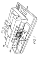
- the document counter comprises a frame 10 which is shown in FIG. 4 of the drawings.
- a support 11 formed substantially as a plate, is mounted at the remote end thereof as seen in FIG. 4 on the frame by means of a shaft (not shown) such that the support is inclined downwards towards a transverse holder beam 12 the lower edge of which forms a holder gap 13 together with the support (FIG. 2).
- the holder gap comprises a slot through Which the documents 14 of a wad of documents located on the support, are to be fed one at a time.
- a feeder cylinder 15, FIG. 3, is rotatably mounted to the frame by means of a horizontal rotational shaft 16.
- the periphery of the feeder cylinder has four guide grooves equally spaced, four conveyor belts 17 extending around a horizontal lift wheel system 18 which is mounted to the frame 10 for displacement in the vertical direction.
- a cam shaft 19 is rotatably mounted to the frame, said shaft being provided with cam wheels 20 contacting lift wheels 21 forming part of the lift wheel system.
- the feeder cylinder forms two diametrically opposite cams 22 for each guide groove therein, FIG. 3, which extend from the bottom of the guide groove to the surface of the feeder cylinder such that the conveyor belts are guided on the periphery of the feeder cylinder at the cams but are located in the guide grooves at other positions.
- flap wheels 23 are located which are rotatably mounted to the frame by means of a horizontal shaft 24.
- the diameter of the flap wheels is substantially as large as the diameter of the feeder cylinder, but the rotational shaft 16 and the rotational shaft 24 are located eccentrically in relation to each other such that the flap wheel always extends beyond the periphery of the feeder cylinder to the region of the later half of the holder gap.
- Each flap wheel is provided with four flaps 25 equally spaced circumferentially. Together with the periphery of the flap wheel, the flaps form four pockets 26 opening in a direction which is opposite to the rotational direction.
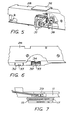
- a receptacle 27 is located adjacent the moving path of the flaps, FIG. 1.
- the holder beam 12 is supported by a bar 28 which is pivotally mounted to the document counter at 29 at one end thereof and can be latched in the position shown in FIG. 1 by means of a latch mechanism.
- This mechanism is operated by means of a push button 30 to make possible that the bar 28 is swung from the position shown in order to uncover the mechanism of the document counter for inspection and service, but above all in order to make possible that the path for the documents is checked for any document having got stuck in the document path.
- Two wheels 31 are rotatably mounted in the bar 28 to engage the periphery of the feeder cylinder 15.
- Two sliding elements 32 e.g.
- each element is mounted to the lower side of the bar 28, each element having a tongue 33 projecting in a direction opposite to the feeding direction of the documents through the document counter.
- These sliding elements are slightly biased by means of springs 34 to engage the conveyor belts 17 while the tongues 33 are located in the space between the conveyor belts.
- the pressure foot 35 pivotally connected to the bar by means of a link 36.
- This pressure foot engages the documents 14 resting on the support 11 and will take a lifted and inclined position in dependence on the thickness of the wad of documents.
- the pressure foot has a guide rail 37 allowing a wad of documents to be inserted under the pressure foot 35 without the necessity of lifting the pressure foot, since this foot is automatically raised when the wad of documents is inserted under the guide rail 37, the outer end portion of which projecting upwards, slides onto the wad of documents while the pressure foot is being lifted.
- a light source such as a LED 38 is provided, which is directed downwards towards the support 11 in which a photocell 39 is provided opposite to the LED 38.
- An electric drive motor (not shown) rotates a shaft 40, FIG. 4, which is rotatably mounted in the frame and in turn rotates the feeder cylinder 15 over a belt 41, the flap wheels 23 over a belt 42, and the cam wheels 20 over a belt 43.
- the ratio is chosen such that the rpm of the feeder cylinder is twice as large as the rpm of the flap wheels, and the rpm of the cam wheels is twice as large as the rpm of the feeder cylinder.
- the rear end of the support is connected to an electromagnet 44 mounted to the frame by means of which the support can be lifted to an idle position wherein the support is located above the level for the conveyor belts lifted by the cam wheels, and can be lowered to a grip position wherein the support is located below the level of the lifted conveyor belts but above the level of the lowered conveyor belts.
- the feeder device operates in the following manner: The rotating elements of the feeder device are synchronized such that the cam wheels 20 have rotated to a position in which they lift the conveyor belts to an elevated gripping position above the level of the support slightly before the cams 22 of the feeder cylinder at the leading ends thereof having been rotated to a position at the holder gap 13. At that moment, the trailing ends of the flaps 25 of the flap wheel system have just passed the holder gap.
- FIG. 3 illustrates this situation.
- the conveyor belt engages the lowermost document of the wad of documents and pushes said document towards the holder gap so that the conveyor belts, when the cams of the feeder cylinder are rotated to a position at the holder gap, are pressed against the lower side of the document over the entire width thereof.
- the document Due to the gap between the document and the conveyor belts the document will slide under the wad of documents together with the conveyor belts to the holder gap, the holder beam simultaneously preventing the rest of the documents to move from the site.
- the cam wheels 20 will immediately rotate to a position in which the lift wheel system with the conveyor belts moves below the level of the support so that the conveyor belts do not touch the document next to the lowermost document in the wad.
- the conveyor belts forward the lowermost document through the holder gap and push the document between the periphery of the feeder cylinder 15 and the periphery of the wheels 31 so that the circumferential surface of the feeder cylinder takes care of the advancement of the document after the cams of the feeder cylinder having passed the holder gap and lower the conveyor belts into the guide grooves.
- the insertion of the document into a pocket 26 formed by the flaps 25 of the flap wheel system will be initiated.
- the feeder cylinder Due to the fact that the feeder cylinder is rotated at double the speed in relation to the flap wheel system, the document will be inserted into the pocket of the flap wheel system at a speed which is higher than the forward speed of the pocket so that the document will reach the bottom of the pocket before the pocket has been rotated to a position at the receptacle 27.
- the document When the document reaches the bottom of the pocket, it has disengaged the wheels 31 so that the flap wheel system retards the advancement of the document and transfers the retarded document to the receptacle.
- the elements of the feeder device have again been rotated to a new gripping position, which means that the cam wheels 20 have been rotated one revolution to the lifting position, the feeder cylinder 15 has been rotated half a revolution to the gripping position, and the flap wheels 23 have been rotated a quarter of a revolution to the receiving position to feed a following document from the wad of documents.
- order is given to the electromagnet 44 in a manner known per se to lift the support 11 to the idle position when the desired number has been fed from the wad of documents so that the conveyor belts do not engage the documents and the support closes the holder gap.
- the order to the electromagnet 44 can be given from an operator's console 45 including an electronic system with the proper program software for counting the documents.
- the sensor system mentioned above and including the LED 38 and the photocell 39 should be connected to the electronic system of the console, and the purpose thereof is to sense the width of a document passing through the document counter.
- the sensed width of the first document is stored in the electronic system and the width measured of all following documents is compared with the width of the document which first passed through the document counter.
- the operation of the apparatus is stopped by means of the electronic system as soon as a deviation of the measured width from the width of the document which first passed through the document counter, is indicated.
- the tongues 33 are directed towards the moving direction of the documents below the holder beam 12 and the purpose thereof is to stop the document next to the last document, should it tend to accompany the lowermost document at withdrawal thereof from the wad of documents.
Landscapes
- Engineering & Computer Science (AREA)
- Mechanical Engineering (AREA)
- Discharge By Other Means (AREA)
- Sheets, Magazines, And Separation Thereof (AREA)
- Transition And Organic Metals Composition Catalysts For Addition Polymerization (AREA)
- Glass Compositions (AREA)
- Lubrication Of Internal Combustion Engines (AREA)
Applications Claiming Priority (2)
| Application Number | Priority Date | Filing Date | Title |
|---|---|---|---|
| SE8401862 | 1984-04-04 | ||
| SE8401862A SE441873B (sv) | 1984-04-04 | 1984-04-04 | Dokumentreknare |
Publications (2)
| Publication Number | Publication Date |
|---|---|
| EP0157752A2 true EP0157752A2 (de) | 1985-10-09 |
| EP0157752A3 EP0157752A3 (de) | 1986-05-28 |
Family
ID=20355444
Family Applications (1)
| Application Number | Title | Priority Date | Filing Date |
|---|---|---|---|
| EP85850120A Withdrawn EP0157752A3 (de) | 1984-04-04 | 1985-04-03 | Vorrichtung zum Zählen von Dokumenten |
Country Status (4)
| Country | Link |
|---|---|
| US (1) | US4624453A (de) |
| EP (1) | EP0157752A3 (de) |
| JP (1) | JPS6116387A (de) |
| SE (1) | SE441873B (de) |
Cited By (1)
| Publication number | Priority date | Publication date | Assignee | Title |
|---|---|---|---|---|
| KR101144040B1 (ko) * | 2005-10-25 | 2012-05-23 | 현대자동차주식회사 | 자동차용 터보차져 |
Families Citing this family (2)
| Publication number | Priority date | Publication date | Assignee | Title |
|---|---|---|---|---|
| EP2149523B1 (de) * | 2008-07-30 | 2012-01-04 | Ricoh Company, Ltd. | Zufuhrvorrichtung und Bildlesegerät, sowie damit versehene Bilderzeugungsvorrichtung |
| DE202011107379U1 (de) * | 2011-10-31 | 2011-11-15 | Francotyp-Postalia Gmbh | Modulare Anlegevorrichtung einer Zuführstation |
Family Cites Families (9)
| Publication number | Priority date | Publication date | Assignee | Title |
|---|---|---|---|---|
| US707220A (en) * | 1901-11-15 | 1902-08-19 | Elliott & Hatch Book Typewriter Company | Feeding attachment for type-writing machines. |
| US2852255A (en) * | 1953-05-22 | 1958-09-16 | E G Staude Mfg Company Inc | Timed bottom feeder |
| NL6512872A (de) * | 1965-10-05 | 1967-04-06 | ||
| US3409290A (en) * | 1966-11-14 | 1968-11-05 | Burroughs Corp | Sheet stacking apparatus |
| FR2011540A1 (de) * | 1968-06-24 | 1970-03-06 | Bobst Fils Sa J | |
| US3912255A (en) * | 1973-10-18 | 1975-10-14 | Pennsylvania Res Ass Inc | Stackers for document counters and the like |
| US4128236A (en) * | 1975-04-07 | 1978-12-05 | Inter Innovation Ab | Sheet feeding apparatus |
| US4054092A (en) * | 1975-09-30 | 1977-10-18 | Brandt-Pra, Inc. | Document counter |
| US4474365A (en) * | 1981-07-30 | 1984-10-02 | Brandt, Inc. | Document feeding, handling and counting apparatus |
-
1984
- 1984-04-04 SE SE8401862A patent/SE441873B/sv not_active IP Right Cessation
-
1985
- 1985-04-03 EP EP85850120A patent/EP0157752A3/de not_active Withdrawn
- 1985-04-03 US US06/719,421 patent/US4624453A/en not_active Expired - Fee Related
- 1985-04-04 JP JP60072513A patent/JPS6116387A/ja active Pending
Cited By (1)
| Publication number | Priority date | Publication date | Assignee | Title |
|---|---|---|---|---|
| KR101144040B1 (ko) * | 2005-10-25 | 2012-05-23 | 현대자동차주식회사 | 자동차용 터보차져 |
Also Published As
| Publication number | Publication date |
|---|---|
| SE8401862D0 (sv) | 1984-04-04 |
| SE8401862L (sv) | 1985-10-05 |
| JPS6116387A (ja) | 1986-01-24 |
| US4624453A (en) | 1986-11-25 |
| SE441873B (sv) | 1985-11-11 |
| EP0157752A3 (de) | 1986-05-28 |
Similar Documents
| Publication | Publication Date | Title |
|---|---|---|
| US4017004A (en) | Paper money dispensing apparatus | |
| US4618302A (en) | Device for accumulating and delivering paper sheets | |
| US4915371A (en) | Device for sorting and stacking paper securities, notably banknotes | |
| CN108479053A (zh) | 一种扑克机及其扑克牌整理方法 | |
| EP0585313A1 (de) | Vorrichtung zum setzen von gegenständen, insbesondere von gefüllten beuteln, in einer schrägrückwärts überlappenden reihe. | |
| EP0793201B1 (de) | Banknotenbearbeitungsmaschine | |
| JPWO1993024402A1 (ja) | 紙片収納装置 | |
| RU2129303C1 (ru) | Счетное устройство для подсчета ценных бумаг, в частности банкнот, обандеролированного пакета ценных бумаг | |
| US4753431A (en) | Note storing apparatus | |
| US4786039A (en) | Recirculating document feeder | |
| US4624453A (en) | Document counter | |
| US4650174A (en) | Method and system for routing a signature for stitching | |
| US5282769A (en) | Coin sorting device with an escalator | |
| US4409773A (en) | Coin wrapping machine | |
| US5482184A (en) | Newspaper conveying mechanism of a newspaper vending | |
| CN115709878B (zh) | 气吸式集成安装型螺丝供料机 | |
| US4476664A (en) | Apparatus for introducing stacks of paper sheets or the like into cartons or analogous receptacles | |
| JPS5856696B2 (ja) | 紙弊などの貯蔵装置 | |
| JPH0646424B2 (ja) | 金券分離機構 | |
| JPH0622694Y2 (ja) | 紙葉類の収納繰出し装置 | |
| JPS586838Y2 (ja) | 紙葉類集積装置 | |
| JPH0422830B2 (de) | ||
| JP2006092188A (ja) | 硬貨包装装置 | |
| US2152179A (en) | Addressing machine | |
| JPS6125283B2 (de) |
Legal Events
| Date | Code | Title | Description |
|---|---|---|---|
| PUAI | Public reference made under article 153(3) epc to a published international application that has entered the european phase |
Free format text: ORIGINAL CODE: 0009012 |
|
| AK | Designated contracting states |
Designated state(s): AT BE CH DE FR GB IT LI LU NL SE |
|
| PUAL | Search report despatched |
Free format text: ORIGINAL CODE: 0009013 |
|
| AK | Designated contracting states |
Kind code of ref document: A3 Designated state(s): AT BE CH DE FR GB IT LI LU NL SE |
|
| 17P | Request for examination filed |
Effective date: 19861003 |
|
| 17Q | First examination report despatched |
Effective date: 19870616 |
|
| STAA | Information on the status of an ep patent application or granted ep patent |
Free format text: STATUS: THE APPLICATION IS DEEMED TO BE WITHDRAWN |
|
| 18D | Application deemed to be withdrawn |
Effective date: 19871229 |
|
| RIN1 | Information on inventor provided before grant (corrected) |
Inventor name: SVENSSON, LENNART |