EP0157741A2 - Container closure with a cap - Google Patents
Container closure with a cap Download PDFInfo
- Publication number
- EP0157741A2 EP0157741A2 EP85810149A EP85810149A EP0157741A2 EP 0157741 A2 EP0157741 A2 EP 0157741A2 EP 85810149 A EP85810149 A EP 85810149A EP 85810149 A EP85810149 A EP 85810149A EP 0157741 A2 EP0157741 A2 EP 0157741A2
- Authority
- EP
- European Patent Office
- Prior art keywords
- cap
- areas
- indentation
- container
- closure
- Prior art date
- Legal status (The legal status is an assumption and is not a legal conclusion. Google has not performed a legal analysis and makes no representation as to the accuracy of the status listed.)
- Withdrawn
Links
Images


Classifications
-
- B—PERFORMING OPERATIONS; TRANSPORTING
- B65—CONVEYING; PACKING; STORING; HANDLING THIN OR FILAMENTARY MATERIAL
- B65D—CONTAINERS FOR STORAGE OR TRANSPORT OF ARTICLES OR MATERIALS, e.g. BAGS, BARRELS, BOTTLES, BOXES, CANS, CARTONS, CRATES, DRUMS, JARS, TANKS, HOPPERS, FORWARDING CONTAINERS; ACCESSORIES, CLOSURES, OR FITTINGS THEREFOR; PACKAGING ELEMENTS; PACKAGES
- B65D50/00—Closures with means for discouraging unauthorised opening or removal thereof, with or without indicating means, e.g. child-proof closures
- B65D50/02—Closures with means for discouraging unauthorised opening or removal thereof, with or without indicating means, e.g. child-proof closures openable or removable by the combination of plural actions
- B65D50/04—Closures with means for discouraging unauthorised opening or removal thereof, with or without indicating means, e.g. child-proof closures openable or removable by the combination of plural actions requiring the combination of simultaneous actions, e.g. depressing and turning, lifting and turning, maintaining a part and turning another one
- B65D50/045—Closures with means for discouraging unauthorised opening or removal thereof, with or without indicating means, e.g. child-proof closures openable or removable by the combination of plural actions requiring the combination of simultaneous actions, e.g. depressing and turning, lifting and turning, maintaining a part and turning another one where one action elastically deforms or deflects at least part of the closure, the container or an intermediate element, e.g. a ring
Definitions
- the invention relates to a container closure with a cap according to the preamble of claim 1.
- Container closures are known in large numbers.
- a container closure is described in CH-PS 556 274, in which the cap is designed as a screw cap. By simply turning the screw cap, this container closure can be opened, since the closure segments are designed as threaded segments.
- a container closure with a rotary cap which has an opening which can be brought into correspondence with the openings in the container.
- latching cams are provided which lock the cap in a locking position. To unlock, it is necessary to overcome a resistance which is provided by the locking device.
- This container closure also has the disadvantage that the locking resistance can be easily overcome by unauthorized persons, in particular also by children, so that the container contents can be accessed by turning the rotating cap.
- the object of the invention is to provide a container closure which has a higher degree of security against unauthorized opening.
- the container closure offers a higher degree of security since the cap can be rotated as desired without opening or exposing an opening. Unauthorized persons, especially children, cannot easily see that the cap has to be pressed in at the indentation areas, so that the container closure ensures a high level of security. Nevertheless, the container closure can be opened very easily by pressing in the indentation areas.
- Claim 2 describes a particularly simple embodiment of the container closure.
- the closure segments are released by pressing in the impression regions and the cap can be lifted off.
- Claim 4 describes a particularly secure configuration of the container closure, since it is necessary here to press in all four indentation areas simultaneously in order to be able to lift off the cap. However, this is only possible with two hands, with two pairs of fingers each having to grip the cap crosswise.
- the cap can have any layout, which can be circular, oval or polygonal.
- an embodiment according to claim 5 is advantageous since the corner regions then simultaneously indicate where the indentation regions are.
- the cap jacket can always have a constant thickness along its circumference.
- an embodiment according to claim 6 is advantageous, which on the one hand makes it easier to press in the cap shell and on the other hand ensures a more targeted expansion of the expansion area.
- the expansion of the expansion area and thus the disengagement of the closure segment can be improved by developing the container closure according to claim 7.
- the safety properties of the container closure can be further improved by a configuration according to claim 8.
- training according to claim 9 is particularly advantageous.
- the safety properties of the container closure guarantee a certain guarantee function.
- the training according to claim 10 is particularly suitable for this.
- the cap is made of plastic and is suitable for containers made of plastic as well as other materials, especially glass.
- the container closure shown in FIGS. 1 and 2 has a cap 2 with a circular cross section, which is attached to a container holder 4 which is provided with a circumferential sealing bead.
- the cap portion 8 of the cap 2 has indentation areas 10, 12 at two diametrically opposite points, which are deformable relative to one another and thereby press expansion areas 14, 16 lying radially between the indentation areas 10, 12, such as the dot-dash shape changes in FIGS. 1 and 2 can be removed.
- Closure segments 18, 20, which are arranged in pairs and which engage under the sealing bead 6, are arranged in pairs on the expansion regions 14, 16 on the inside of the cap jacket 8.
- the cap jacket 8 is provided on the inside of the indentation areas 10, 12 with projecting locking cams 22 which are ineffective in the unlocked position shown in FIGS. 1 and 2.
- the locking cams 22 interact with locking cams 34 on the container holder 4, which contain locking recesses 24.
- this latching device has the effect that in this locking position the indentation areas 10, 12 cannot be pressed in, since they rest on the locking cams 23. Since the latching recesses 24 are undercut, as can be seen from FIG. 2, the latching cams 22 in the locked state further strengthen the hold of the cap 2 on the container holder 4.
- the latching device also prevents the cap 2 from being pivoted out of the locked position into the unlocking position of FIG. 1 prevented.
- the cap jacket 8 is provided on the outside at the indentation areas 10, 12 with finger recesses 26, which are aligned in the unlocking position with finger recesses 28 which are arranged on the outside of the container.
- the finger troughs 26 on the cap shell 8 on the one hand denote the indentation areas 10, 12 of the cap shell and, when they match the finger troughs 28 on the container, indicate the unlocked position of the container closure.
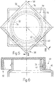
- Figures 3 to 6 show a further container closure with a cap 30 which has a polygonal, i.e. has a square floor plan.
- the cap 30 is placed on a container holder 32, which in turn is provided with a circumferential sealing bead 34.
- the cap shell 36 is provided with an indentation area 38. Between the indentation areas 38 there are expansion areas 40 with closure segments 42 which engage behind the circumferential closure bead 34.
- the container closure is equipped with a guarantee device, which has guarantee bands 44, which are formed in the corner regions of the cap 30 at the lower edge of the cap shell 36.
- the guarantee bands lie radially on the safety cams of the container holder 32 and on the one hand prevent unauthorized twisting of the cap 30 or on the other hand prevent the pressing-in areas 38 from being pressed in. As long as the guarantee bands 44 are intact, this is a guarantee that the container is still in its original condition.
- Figures 7 and 8 show a further container closure, which is designed similar to that of Figures 3 to 6.
- the cap 48 has a square outline and is arranged on the container holder 50, which is provided with a circumferential sealing bead 52. With this closure points the cap jacket 54 only two indentation areas 56 arranged at opposite corner areas. At a corner lying between the indentation areas 56, the cap jacket is designed as an expansion area 58 and contains a locking segment 60 which engages behind the locking bead 52 of the container holder 50.
- the cap shell 54 is configured at the corner opposite the expansion region 58 such that practically no expansion of the cap shell takes place when the indentation regions 56 are pressed in.
- Two further closure segments 62 are arranged between the indentation areas 56 and the fourth corner of the cap 48, which also engage behind the closure bead 52.
- the closure segments 60, 62 are evenly distributed over the circumference of the container holder 50.
- the cap jacket 54 is designed such that when pressure is applied to the push-in areas 56, the expansion takes place practically exclusively at the expansion area 58, while the cap jacket 54 at the opposite corner remains practically unchanged.
- weakening points 64, 66 are arranged on the indentation areas 56 and on the expansion area 58, which facilitate the indentation of the cap portion 54 on the indentation area 56 and promote the buckling of the cap portion on the expansion area 58.
- the cap jacket is tapered in the area 68 between the push-in area 56 and the closure segment 62 and stiffened in the area 70 between the push-in area 56 and the expansion area 58.
- the container closure according to FIGS. 7 and 8 is provided with a guarantee tape analogous to the example in FIGS. 3 to 6.
Landscapes
- Engineering & Computer Science (AREA)
- Mechanical Engineering (AREA)
- Closures For Containers (AREA)
Abstract
Description
Die Erfindung betrifft einen Behälterverschluss mit einer Kappe gemäss Oberbegriff des Anspruches 1.The invention relates to a container closure with a cap according to the preamble of claim 1.
BehäLterverschLüsse sind in grosser ZahL bekannt. So ist beispielsweise in der CH-PS 556 274 ein Behälterverschluss beschrieben, bei dem die Kappe aLs Schraubkappe ausgebildet ist. Durch einfaches Drehen der Schraubkappe kann dieser BehäLterverschLuss geöffnet werden, da die VerschLusssegmente aLs Gewindesegmente ausgebildet sind. Für bestimmte Produkte ist es jedoch erwünscht oder erforderLich, dass ein BehäLter einen Behälterverschluss aufweist, der nicht so ohne weiteres zu öffnen ist, um den Zugang des Produktes für Unbefugte, insbesondere Kinder zu erschweren. Hierzu ist es bekannt, einen BehäLterverschLuss mit einer Drehkappe zu versehen, die eine Oeffnung aufweist, welche durch Verdrehen mit Oeffnungen im BehäLter in Uebereinstimmung gebracht werden kann. Um das Drehen des Kappe für Unbefugte zu erschweren, sind Rastnocken vorhanden, welche die Kappe in einer Verriegelungsstellung verriegeln. Zum EntriegeLn ist die Ueberwindung eines Widerstandes erforderlich, der durch Rastvorrichtung gegeben ist. Auch dieser Behälterverschluss weist den NachteiL auf, dass der Rastwiderstand von Unbefugten, insbesondere auch von Kindern, Leicht überwunden werden kann, sodass durch Verdrehen der Drehkappe der BehäLterinhaLt zugänglich wird.Container closures are known in large numbers. For example, a container closure is described in CH-PS 556 274, in which the cap is designed as a screw cap. By simply turning the screw cap, this container closure can be opened, since the closure segments are designed as threaded segments. For certain products, however, it is desirable or required that a container have a container closure that is not easily opened in order to make it difficult for unauthorized persons, especially children, to access the product. For this purpose it is known to provide a container closure with a rotary cap which has an opening which can be brought into correspondence with the openings in the container. To make it difficult for unauthorized persons to turn the cap, latching cams are provided which lock the cap in a locking position. To unlock, it is necessary to overcome a resistance which is provided by the locking device. This container closure also has the disadvantage that the locking resistance can be easily overcome by unauthorized persons, in particular also by children, so that the container contents can be accessed by turning the rotating cap.
Aufgabe der Erfindung ist es, einen Behälterverschluss zu schaffen, der ein höheres Mass an Sicherheit gegen unbefugtes Oeffnen aufweist.The object of the invention is to provide a container closure which has a higher degree of security against unauthorized opening.
Die Aufgabe wird erfindungsgemäss durch die kennzeichnenden MerkmaLe des Anspruches 1 gelöst.The object is achieved according to the invention by the characterizing features of claim 1.
Dadurch, dass die Kappe mittels VerschLusssegmente und einem umlaufenden Verschlusswulst Lösbar am BehäLterhaLs gehalten ist, und nur durch Eindrücken an den Eindrückbereichen ein Ausbiegen des Expansionsbereiches und damit gleichzeitig auch ein Lösen des VerschLusssegmentes möglich ist, bietet der Behälterverschluss ein höheres Mass an Sicherheit, da an der Kappe beliebig gedreht werden kann, ohne dass sie aufgeht oder eine Oeffnung freigelegt wird. Dass zum Oeffnan der Kappe der KappenmanteL an den Eindrückbereichen eingedrückt werden muss, ist für Unbefugte, insbesondere Kinder, nicht so ohne weiteres erkennbar, sodass der Behälterverschluss ein hohes Mass an Sicherheit gewährleistet. Dennoch kann der Behätterverschluss durch Eindrücken der Eindrückbereiche sehr Leicht geöffnet werden.Due to the fact that the cap is detachably held on the container by means of closure segments and a circumferential sealing bead, and only by pressing in on the indentation areas is it possible to bend out the expansion area and thus at the same time also to release the closure segment, the container closure offers a higher degree of security since the cap can be rotated as desired without opening or exposing an opening. Unauthorized persons, especially children, cannot easily see that the cap has to be pressed in at the indentation areas, so that the container closure ensures a high level of security. Nevertheless, the container closure can be opened very easily by pressing in the indentation areas.
VorteiLhafte AusgestaLtungen des Behälterverschlusses sind in den Ansprüchen 2 bis 10 beschrieben.Advantageous configurations of the container closure are described in
Eine besonders einfache AusgestaLtung des Behätterverschlusses beschreibt Anspruch 2. Durch Eindrücken der Eindrückbereiche werden die VerschLusssegmente gelöst und die Kappe kann abgehoben werden.
Vorteilhaft ist auch eine AusgestaLtung des Behälterverschlusses nach Anspruch 3, da hier ein Eindrücken der Eindrückbereiche noch nicht zum vollständigen Lösen der VerschLusssegmente führt. Es wird dann nur das im Expansionsbereich angeordnete VerschLusssegment gelöst und die Kappe muss durch Kippen um die im Einsatz verbleibenden VerschLusssegmente geöffnet werden. Dadurch wird die Sicherheit des BehäLterverschlusses vergrössert.It is also advantageous to design the container closure according to claim 3, since pressing in the indentation areas does not yet lead to complete loosening of the closure segments. Then only the closure segment arranged in the expansion area is released and the cap must be opened by tilting around the closure segments remaining in use. This increases the security of the container closure.
Der Anspruch 4 beschreibt eine besonders sichere AusgestaLtung des Behälterverschlusses, da es hier erfoderlich ist, alle vier Eindrückbereiche gleichzeitig einzudrücken, um die Kappe abheben zu können. Dies ist allerdings nur mit zwei Händen möglich, wobei zwei Fingerpaare jeweils über Kreuz an der Kappe angreifen müssen.
Die Kappe kann einen beliebigen Grundriss aufweisen, der kreisrund, oval oder mehreckig sein kann. Dabei ist eine Ausgestaltung nach Anspruch 5 von Vorteil, da dann die Eckbereiche gleichzeitig angeben, wo die Eindrückbereiche sind.The cap can have any layout, which can be circular, oval or polygonal. In this case, an embodiment according to claim 5 is advantageous since the corner regions then simultaneously indicate where the indentation regions are.
An sich kann der Kappenmantel Längs seines Umfanges eine stets gleichbleibende Dicke aufweisen. Von Vorteil ist jedoch eine AusgestaLtung nach Anspruch 6, wodurch einerseits das Eindrücken des KappenmanteLs erleichtert wird und zum andern eine gezieltere Expansion des Expansionsbereiches gewährleistet wird. Das Expandieren des Expansionsbereiches und damit das Ausrasten des VerschLusssegmentes kann durch eine Weiterbildung des Behälterverschlusses nach Anspruch 7 verbessert werden.As such, the cap jacket can always have a constant thickness along its circumference. However, an embodiment according to
Die Sicherheitseigenschaften des Behälterverschlusses Lassen sich durch eine AusgestaLtung nach Anspruch 8 weiter verbessern. Hierzu ist eine AusbiLdung nach Anspruch 9 besonders vorteilhaft.The safety properties of the container closure can be further improved by a configuration according to
An sich gewährleisten schon die Sicherheitseigenschaften des Behälterverschlusses eine gewisse Garantiefunktion. VorteiLhaft ist es jedoch, den Behälterverschluss mit üblichen Garantiervorrichtungen auszustatten. Hierzu ist die AusbiLdung nach Anspruch 10 besonders geeignet.In itself, the safety properties of the container closure guarantee a certain guarantee function. However, it is advantageous to equip the container closure with the usual guarantee devices. The training according to
Die Kappe besteht aus Kunststoff und ist für BehäLter sowohl aus Kunststoff wie auch aus anderem MateriaL, insbesondere GLas geeignet.The cap is made of plastic and is suitable for containers made of plastic as well as other materials, especially glass.
Ausführungsbeispiele des erfindungsgemässen Behälterverschlusses werden nachfolgend anhand der Zeichnungen näher beschrieben, dabei zeigen:
- Figur 1 einen Behälterverschluss mit einer im Grundriss kreisrunden Kappe in Draufsicht;
Figur 2 den BehäLterverschLuss der Figur 1 im Schnitt II-II der Figur 1;- Figur 3 einen weiteren Behälterverschluss mit im Grundriss viereckiger Kappe und vier Eindrückbereichen an den Ecken, im Grundriss;
Figur 4 den Behälterverschluss der Figur 3 im Schnitt IV-IV der Figur 3;- Figur 5 den Behälterverschluss der Figur 3 nach Absprengen des Garantiebandes;
Figur 6 den Behälterverschluss der Figur 5 im Schnitt VI-VI der Figur 5;- Figur 7 einen weiteren BehäLterverschLuss mit im Grundriss viereckigem DeckeL, jedoch mit zwei Eindrückbereichen im Grundriss;
Figur 8 den Behälterverschluss der Figur 7 in der DarsteLLung gemäss Figur 5.
- Figure 1 shows a container closure with a circular cap in plan in plan view;
- Figure 2 shows the container closure of Figure 1 in section II-II of Figure 1;
- Figure 3 shows another container closure with a square cap in plan and four indentation areas at the corners, in plan;
- Figure 4 shows the container closure of Figure 3 in section IV-IV of Figure 3;
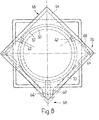
- FIG. 5 shows the container closure of FIG. 3 after the guarantee band has broken off;
- Figure 6 shows the container closure of Figure 5 in section VI-VI of Figure 5;
- FIG. 7 shows a further container closure with a square ceiling in plan, but with two indentation areas in plan;
- 8 shows the container closure of FIG. 7 in the illustration according to FIG. 5.
Der in den Figuren 1 und 2 gezeigte Behälterverschluss weist eine Kappe 2 mit kreisrundem Querschnitt auf, die an einem BehäLterhaLs 4 angesetzt ist, der mit einem umlaufenden Verschlusswulst versehen ist. Der KappenmanteL 8 der Kappe 2 weist an zwei diametral gegenüberliegenden SteLLen Eindrückbereiche 10, 12 auf, die gegeneinander verformbar sind und dabei zwischen den Eindrückbereichen 10, 12 Liegende Expansionsbereiche 14, 16 radial nach aussen drücken, wie den strichpunktierten Formänderungen in den Figuren 1 und 2 entnommen werden kann. An den Expansionsbereichen 14, 16 sind auf der Innenseite des KappenmanteLs 8 jeweils paarweise angeordnete VerschLusssegmente 18, 20 angeordnet, die den Verschlusswulst 6 untergreifen.The container closure shown in FIGS. 1 and 2 has a
Der Kappenmantel 8 ist an den Eindrückbereichen 10, 12 auf der Innenseite mit vorspringenden Rastnocken 22 versehen, die in der in den Figuren 1 und 2 gezeigten entriegelten StelLung wirkungslos sind. Wird die Kappe 2 jedoch um 90° verschwenkt, so wirken die Rastnocken 22 mit Sperrnocken 34 am BehäLterhaLs 4 zusammen, die Rastausnehmungen 24 enthalten. Diese Rastvorrichtung bewirkt einerseits, dass in dieser Verriegelungsstellung die Eindrückbereiche 10, 12 nicht eingedrückt werden können, da sie an den Sperrnocken 23 anLiegen. Da die Rastausnehmungen 24 hinterschnitten sind, wie aus Figur 2 hervorgeht, verstärken die Rastnocken 22 im verriegeLten Zustand ferner den HaLt der Kappe 2 am BehäLterhaLs 4. Durch die Rastvorrichtung wird überdies ein ungewolltes Verschwenken der Kappe 2 aus der Verriegelungsstellung in die EntriegeLungssteLLung der Figur 1 verhindert.The
Der KappenmanteL 8 ist auf der Aussenseite an den Eindrückbereichen 10, 12 mit Fingermulden 26 versehen, die in der EntriegeLungssteLLung mit Fingermulden 28 fluchten, die an der Behälteraussenseite angeordnet sind. Die FingermuLden 26 am KappenmanteL 8 bezeichnen einerseits die Eindrückbereiche 10, 12 des KappenmanteLs und geben bei Uebereinstimmung mit den Fingermulden 28 am BehäLter die EntriegeLungsstellung des BehäLterverschLusses an.The
Zum Verschliessen des BehäLters ist es LedigLich erforderLich, die Kappe auf den BehäLterhaLs 4 aufzudrücken, wobei die VerschLusssegmente 18, 20 am umlaufenden Verschlusswulst 6 einrasten- Zum Oeffnen des Behätterverschlusses ist es erforderLich, die Kappe in die EntriegeLungssteLLung zu verschwenken und den KappenmanteL 8 durch Eindrücken der Eindrückbereiche 10, 12 zu verformen. Dadurch wird der Kappenmantel 8 an den Expansionsbereichen 14, 16 radial nach aussen gedrückt, so dass die Verschlusssegmente 18, 20 von dem umlaufenden Verschlusswulst 6 freikommen, wie strichpunktiert in den Figuren 1 und 2 angegeben ist. Daraufhin kann die Kappe 2 nach oben abgezogen werden.To close the container, it is only necessary to press the cap onto the
Die Figuren 3 bis 6 zeigen einen weiteren Behälterverschluss mit einer Kappe 30, die einen mehreckigen, d.h. viereckigen Grundriss aufweist. Die Kappe 30 ist auf einen BehäLterhaLs 32 aufgesetzt, der wiederum mit einem umlaufenden VerschLusswulst 34 versehen ist. An den Ecken ist der KappenmanteL 36 jeweiLs mit einem Eindrückbereich 38 versehen. Zwischen den Eindrückbereichen 38 Liegen Expansionsbereiche 40 mit Verschlusssegmenten 42, die den umlaufenden Verschtusswulst 34 hintergreifen.Figures 3 to 6 show a further container closure with a
Der Behälterverschluss ist mit einer Garantievorrichtung ausgestattet, die Garantiebänder 44 aufweist, welche in den Eckbereichen der Kappe 30 am unteren Rand des KappenmanteLs 36 angeformt sind. Die Garantiebänder Liegen radial an Sicherheitsnocken des BehäLterhaLses 32 an und verhindern einerseits ein unbefugtes Verdrehen der Kappe 30 bzw. andererseits ein unbefugtes Eindrücken der Eindrückbereiche 38. SoLange die Garantiebänder 44 intakt sind, ist dies eine Gewähr dafür, dass der BehäLter noch den Originalzustand aufweist.The container closure is equipped with a guarantee device, which has
Zum Oeffnen des BehäLters ist es erforderlich, die Kappe 30 soweit zu verschwenken, dass die Garantiebänder 44 abgesprengt werden. Hierzu genügt ein Verschwenken um 450, wie aus Figur 5 und 6 ersichtlich ist. Zum Oeffnen des BehäLterverschlusses müssen aLLe vier Eindrückbereiche 38 an den Ekken der Kappe 30 eingedrückt werden, worauf die Expansionsbereiche 40 radial nach aussen gedrängt werden und die Verschlusssegmente 42 den umlaufenden Verschlusswulst 34 freigeben, wie dies in der unteren HäLfte der Figur 5 und in Figur 6 strichpunktiert angedeutet ist. Wenn das Garantieband 44 einmal abgesprengt ist, kann der BehäLterverschLuss in jeder beliebigen SteLLung der Kappe 30 vom BehäLter angenommen werden.To open the container, it is necessary to pivot the
Die Figuren 7 und 8 zeigen einen weiteren Behälterverschluss, der ähnlich jenem der Figuren 3 bis 6 ausgebildet ist. Die Kappe 48 weist einen viereckigen Grundriss auf und ist am BehäLterhaLs 50 angeordnet, der mit einem umlaufenden Verschlusswulst 52 versehen ist. Bei diesem VerschLuss weist der KappenmanteL 54 LedigLich zwei an gegenüberliegenden Eckbereichen angeordnete Eindrückbereiche 56 auf. An einer zwischen den Eindrückbereichen 56 Liegenden Ecke ist der Kappenmantel als Expansionsbereich 58 ausgebildet und enthält ein VerschLusssegment 60, welches den Verschlusswulst 52 des BehäLterhaLses 50 hintergreift. Der KappenmanteL 54 ist an der dem Expansionsbereich 58 gegenüberliegenden Ecke so ausgestaltet, dass praktisch keine Expansion des KappenmanteLs stattfindet, wenn die Eindrückbereiche 56 eingedrückt werden. Zwischen den Eindrückbereichen 56 und der vierten Ecke der Kappe 48 sind zwei weitere VerschLusssegmente 62 angeordnet, die ebenfalls den VerschLusswulst 52 hintergreifen. Die Verschlusssegmente 60, 62 sind gleichmässig am Umfang des BehäLterhaLses 50 verteilt.Figures 7 and 8 show a further container closure, which is designed similar to that of Figures 3 to 6. The
Der KappenmanteL 54 ist so ausgestaltet, dass bei einem Druck auf die Eindrückbereiche 56 die Expansion praktisch ausschLiessLich am Expansionsbereich 58 stattfindet, während der KappenmanteL 54 an der gegenüberliegenden Ecke praktisch unverändert bleibt. Hierzu sind an den Eindrückbereichen 56 sowie am Expansionsbereich 58 Schwächungsstellen 64, 66 angeordnet, welche ein Eindrücken des KappenmanteLs 54 am Eindrückbereich 56 erleichtern und das Knicken des KappenmanteLs am Expansionsbereich 58 begünstigen. Um die Kraft beim Eindrücken des KappenmanteLs 54 am Eindrückbereich 56 möglichst ungehindert an den Expansionsbereich 58 weitergeben zu können, ist der Kappenmantel im Bereich 68 zwischen dem Eindrückbereich 56 und dem Verschlusssegment 62 verjüngt und im Bereich 70 zwischen dem Eindrückbereich 56 und dem Expansionsbereich 58 versteift.The
Bei dieser AusbiLdung des Behälterverschlusses bewirkt ein Druck auf die Eindrückbereiche 56 eine praktisch ausschliess-Liche Expansion des Expansionsbereiches 58 und damit ein Abheben des VerschLusssegmentes 60. Eine Expansion des dem Expansionsbereich gegenüberliegenden Eckbereiches und ein Abheben der weiteren VerschLusssegmente 62 findet nicht statt, sodass zum Abheben der Kappe diese am Expansionsbereich 58 angehoben und um die weiteren Verschlusssegmente 62 abgekippt werden muss.With this configuration of the container closure, pressure on the
Der Behälterverschluss gemäss den Figuren 7 und 8 ist mit einem Garantieband analog dem Beispiel der Figuren 3 bis 6 versehen.The container closure according to FIGS. 7 and 8 is provided with a guarantee tape analogous to the example in FIGS. 3 to 6.
Es sind zahlreiche weitere AusführungsbeispieLe denkbar, wobei insbesondere diverse Garantievorrichtungen bekannter Art zum Einsatz kommen können. Ausserdem sind verschiedene Elemente der einzelnen AusführungsbeispieLe untereinander austauschbar und kombinierbar.Numerous further exemplary embodiments are conceivable, and in particular various known guarantee devices can be used. In addition, various elements of the individual design examples are interchangeable and combinable.
- 2 Kappe2 cap
- 4 BehäLterhaLs4 CONTAINERS
- 6 Verschlussuutst6 closure
- 8 KappenmanteL8 cap coats
- 10 Eindrückbereich10 indentation area
- 12 Eindrückbereich12 indentation area
- 14 Expansionsbereich14 expansion area
- 16 Expansionsbereich16 expansion area
- 18 VerschLusssegment18 locking segment
- 20 Verschlusssegment20 locking segment
- 22 Rastnocken22 locking cams
- 23 Sperrnocken23 locking cams
- 24 Rastenausnehmung24 notch
- 26 FingermuLde26 finger rest
- 28 Fingermulde28 finger recess
- 30 Kappe30 cap
- 32 BehäLterhaLs32 CONTAINERS
- 34 Verschlusswulst34 sealing bead
- 36 KappenmanteL36 cap coat
- 38 Eindrückbereich38 indentation area
- 40 Expansionsbereich40 expansion area
- 42 Verschlusssegment42 locking segment
- 44 Garantieband44 guarantee tape
- 46 Sicherungsnocke46 safety cam
- 48 Kappe48 cap
- 50 BehäLterhaLs50 CONTAINERS
- 52 Verschlusswulst52 sealing bead
- 54 KappenmanteL54 cap coat
- 56 Eindrückbereich56 indentation area
- 58 Expansionsbereich58 expansion area
- 60 Verschlusssegment60 locking segment
- 62 Verschlusssegment62 locking segment
- 64 Schwächungsstelle64 weakening point
- 66 Schwächungsstelle66 weakening point
- 68 verjüngter Bereich68 tapered area
- 70 versteifter Bereich70 stiffened area
Claims (10)
Applications Claiming Priority (2)
| Application Number | Priority Date | Filing Date | Title |
|---|---|---|---|
| CH168284 | 1984-04-03 | ||
| CH1682/84 | 1984-04-03 |
Publications (2)
| Publication Number | Publication Date |
|---|---|
| EP0157741A2 true EP0157741A2 (en) | 1985-10-09 |
| EP0157741A3 EP0157741A3 (en) | 1986-12-30 |
Family
ID=4216128
Family Applications (1)
| Application Number | Title | Priority Date | Filing Date |
|---|---|---|---|
| EP85810149A Withdrawn EP0157741A3 (en) | 1984-04-03 | 1985-04-02 | Container closure with a cap |
Country Status (3)
| Country | Link |
|---|---|
| US (1) | US4588097A (en) |
| EP (1) | EP0157741A3 (en) |
| DE (1) | DE8510030U1 (en) |
Families Citing this family (29)
| Publication number | Priority date | Publication date | Assignee | Title |
|---|---|---|---|---|
| US4775062A (en) * | 1987-04-10 | 1988-10-04 | Berry Plastics, Inc. (Indiana Corp.) | Child resistant closure cap for necked cans or containers |
| EP0354283A1 (en) * | 1988-08-10 | 1990-02-14 | Gilbert Plastics | A child resistant closure cap for necked cans or containers |
| US5328058A (en) * | 1990-05-03 | 1994-07-12 | Nalge Company | Dropper bottle assembly with squeeze cap |
| US5310074A (en) * | 1993-06-25 | 1994-05-10 | Berry Plastics Corporation | Canister with lid-release control mechanism |
| US5449077A (en) * | 1994-09-13 | 1995-09-12 | Seidler; David | Bottle with child resistant cap |
| US5687863A (en) * | 1996-01-30 | 1997-11-18 | Owens-Illinois Closure Inc. | Squeeze and turn child resistant package |
| US5845798A (en) * | 1997-03-15 | 1998-12-08 | The Procter & Gamble Company | Closure assembly having a deformable anti-backoff feature independent of the screw threads |
| US6343705B1 (en) | 1997-10-14 | 2002-02-05 | Rexam Medical Packaging Inc. | Closure having back-angled lugs |
| US6152315A (en) * | 1997-10-14 | 2000-11-28 | Rexam Plastics Inc. | Closure having back-angled lugs |
| US6053343A (en) * | 1998-05-14 | 2000-04-25 | Kerr Group, Inc. | Child-resistant closure and container with tamper indication |
| US7100785B1 (en) * | 1999-10-18 | 2006-09-05 | Alpla-Werke Alwin Lehner Gmbh & Co.Kg | Closure cap cooperating with a bottle type container |
| US6640987B2 (en) | 1999-11-30 | 2003-11-04 | Kerr Group, Inc. | Child resistant closure and container having axially offset locking teeth |
| JP2002073406A (en) * | 2000-08-30 | 2002-03-12 | Matsushita Electric Ind Co Ltd | Control device for memory access |
| US6854613B2 (en) * | 2003-05-09 | 2005-02-15 | Drug Plastics & Glass Company, Inc. | Container and child-resistant closure system |
| US20050263477A1 (en) | 2003-10-13 | 2005-12-01 | Konefal Robert S | Closure and container package with child-resistant and non-child-resistant modes of operation |
| JP4416612B2 (en) * | 2004-09-17 | 2010-02-17 | ダイキョーニシカワ株式会社 | cap |
| US7942279B2 (en) * | 2005-04-06 | 2011-05-17 | Mcneill-Ppc, Inc. | Device and method for packaging and merchandising personal healthcare products |
| US20060273060A1 (en) * | 2005-06-06 | 2006-12-07 | Mark Fricke | Reversible vial closure |
| FR2911329B1 (en) * | 2007-01-12 | 2009-04-17 | Rexam Pharma Soc Par Actions S | PACKAGING AND DISPENSING ASSEMBLY OF A MEDICAL LIQUID |
| JP2008189358A (en) * | 2007-02-06 | 2008-08-21 | Saraya Kk | Liquid discharging container |
| US8123058B2 (en) | 2008-09-11 | 2012-02-28 | Rexam Healthcare Packaging Inc. | Closure with stopping mechanism |
| US8079483B2 (en) | 2008-09-11 | 2011-12-20 | Rexam Healthcare Packaging Inc. | Closure with stopping mechanism |
| US8245880B1 (en) | 2009-06-04 | 2012-08-21 | Berry Plastics Corporation | Closure with rotational stop |
| SE535456C2 (en) | 2010-10-18 | 2012-08-14 | Swedish Match North Europe Ab | Child safe container |
| US9545264B2 (en) * | 2014-06-06 | 2017-01-17 | Surgiquest, Inc. | Trocars and obturators |
| WO2019104043A1 (en) * | 2017-11-21 | 2019-05-31 | Drug Platics & Glass Company, Inc. | Child-resistant single wall squeeze and turn closure and container assembly |
| US11794962B2 (en) * | 2018-04-20 | 2023-10-24 | Roy + Leclair Emballage Inc. | Bottle cap assembly |
| WO2022180283A1 (en) | 2021-02-25 | 2022-09-01 | Quadpack Industries S.A. | Closure system for lidded containers |
| AU2021448685A1 (en) * | 2021-06-01 | 2023-12-21 | Cr Packaging Llc | Containers and methods of using the same |
Citations (5)
| Publication number | Priority date | Publication date | Assignee | Title |
|---|---|---|---|---|
| US2585624A (en) * | 1950-05-08 | 1952-02-12 | Hazel Atlas Glass Co | Thread for glass containers |
| US3907103A (en) * | 1973-07-16 | 1975-09-23 | Howard G Shaw | Safety container |
| GB1511664A (en) * | 1976-10-25 | 1978-05-24 | Reymes Cole B | Containers with closures |
| FR2475007A1 (en) * | 1980-01-31 | 1981-08-07 | Perinet Philippe | Safety stopper for cylindrical container - has rolled flange at one end with two lugs on stopper fitting under flange |
| US4452363A (en) * | 1982-09-12 | 1984-06-05 | Johnsen & Jorgenson (Plastics) Ltd. | Tamper-resistant and child-resistant container and cap assembly |
Family Cites Families (2)
| Publication number | Priority date | Publication date | Assignee | Title |
|---|---|---|---|---|
| US4376497A (en) * | 1980-09-15 | 1983-03-15 | Owens-Illinois, Inc. | Child resistant dispensing closure |
| US4335823A (en) * | 1981-01-26 | 1982-06-22 | Sunbeam Plastics Corporation | Child-resistant package |
-
1985
- 1985-04-02 US US06/718,874 patent/US4588097A/en not_active Expired - Fee Related
- 1985-04-02 EP EP85810149A patent/EP0157741A3/en not_active Withdrawn
- 1985-04-03 DE DE8510030U patent/DE8510030U1/en not_active Expired
Patent Citations (5)
| Publication number | Priority date | Publication date | Assignee | Title |
|---|---|---|---|---|
| US2585624A (en) * | 1950-05-08 | 1952-02-12 | Hazel Atlas Glass Co | Thread for glass containers |
| US3907103A (en) * | 1973-07-16 | 1975-09-23 | Howard G Shaw | Safety container |
| GB1511664A (en) * | 1976-10-25 | 1978-05-24 | Reymes Cole B | Containers with closures |
| FR2475007A1 (en) * | 1980-01-31 | 1981-08-07 | Perinet Philippe | Safety stopper for cylindrical container - has rolled flange at one end with two lugs on stopper fitting under flange |
| US4452363A (en) * | 1982-09-12 | 1984-06-05 | Johnsen & Jorgenson (Plastics) Ltd. | Tamper-resistant and child-resistant container and cap assembly |
Also Published As
| Publication number | Publication date |
|---|---|
| DE8510030U1 (en) | 1985-06-05 |
| US4588097A (en) | 1986-05-13 |
| EP0157741A3 (en) | 1986-12-30 |
Similar Documents
| Publication | Publication Date | Title |
|---|---|---|
| EP0157741A2 (en) | Container closure with a cap | |
| DE2600410C2 (en) | Container with associated safety lock | |
| DE69309951T2 (en) | CONTAINER LOCK WITH ORIGINALITY TAPE | |
| DE3885608T2 (en) | Locking device with childproof locking cap. | |
| DE69704567T2 (en) | CAP | |
| EP0225394A1 (en) | Tamper-proof closure | |
| DE3218651A1 (en) | CHILD SAFE CONTAINER | |
| DE2543251A1 (en) | CONTAINER LOCK | |
| DE2840761A1 (en) | CONTAINER LOCK | |
| DE2156654A1 (en) | Safety lock | |
| DE3416179C2 (en) | ||
| DE2655663A1 (en) | LOCK FOR A CONTAINER | |
| EP0254673A1 (en) | Container closure provided with a tamper indicating band | |
| DE3346928A1 (en) | ORIGINAL ASSURED LOCKING ARRANGEMENT | |
| EP0123810A1 (en) | Child-resistant closure | |
| WO2003037737A1 (en) | Container with a security closure | |
| CH667249A5 (en) | PLASTIC LOCK WITH GUARANTEE BAND. | |
| DE2249009A1 (en) | SECURITY LATCH | |
| CH624073A5 (en) | Closure device for bottles, jugs and similar containers | |
| DE4318311C2 (en) | Safety screw cap for a container | |
| EP0569897A1 (en) | Child resistant device for closing containers | |
| EP0498954B1 (en) | Closure cap for plastic closure | |
| DE69622060T2 (en) | Childproof locking arrangement | |
| EP0631943A2 (en) | Container closure | |
| DE2755758C2 (en) | Tamper-evident closure with a perforation arranged between two parts |
Legal Events
| Date | Code | Title | Description |
|---|---|---|---|
| PUAI | Public reference made under article 153(3) epc to a published international application that has entered the european phase |
Free format text: ORIGINAL CODE: 0009012 |
|
| AK | Designated contracting states |
Designated state(s): AT BE DE FR GB IT LU NL |
|
| PUAL | Search report despatched |
Free format text: ORIGINAL CODE: 0009013 |
|
| AK | Designated contracting states |
Kind code of ref document: A3 Designated state(s): AT BE DE FR GB IT LU NL |
|
| STAA | Information on the status of an ep patent application or granted ep patent |
Free format text: STATUS: THE APPLICATION IS DEEMED TO BE WITHDRAWN |
|
| 18D | Application deemed to be withdrawn |
Effective date: 19870701 |